

Atlona AT-HDR-EX-100CEA-KIT Installation Manual
1
Installation Guide
AT-HDR-EX-100CEA-KIT
4K HDR HDMI over 100 M HDBaseT™ TX/RX
with Ethernet, Control, PoE, and Return Audio
AT-HDR-EX-100CEA-KIT
The Atlona AT-HDR-EX-100CEA-KIT is an HDBaseT transmitter/receiver kit for high dynamic
range (HDR) formats. The kit is HDCP 2.2 compliant and supports 4K/UHD video @ 60 Hz with
4:4:4 chroma sampling, as well as HDMI data rates up to 18 Gbps. The HDR-EX-100CEA-KIT
provides transmission of HDMI, Ethernet pass-through, and bidirectional IR and RS-232 control
signals up to 330 feet (100 meters) over CAT6a/7 cable. This extender kit features visually
lossless compression with no latency to enable HDR and 4K/60 4:4:4 video signal extension over
HDBaseT. For additional integration convenience, the transmitter remotely powers the receiver
through Power over Ethernet (PoE). The HDR-EX-100CEA-KIT can transmit digital audio from a
television back to an AV receiver, via a dedicated audio pathway.
The HDR-EX-100CEA-KIT is ideal for residential and commercial applications with the latest
as well as emerging 4K/UHD and HDR sources and displays. It is compatible with all video
resolutions, audio formats, and color space formats supported in the HDMI 2.0b specication,
plus the ability to pass metadata for HDR content. The HDR-EX-100CEA-KIT includes Atlona’s
award-winning 10 year limited product warranty and customer support services, so that
integrators can specify, purchase, and install with condence.
IMPORTANT: Visit http://www.atlona.com/product/AT-HDR-EX-100CEA-KIT for the
latest rmware updates and Installation Guide.
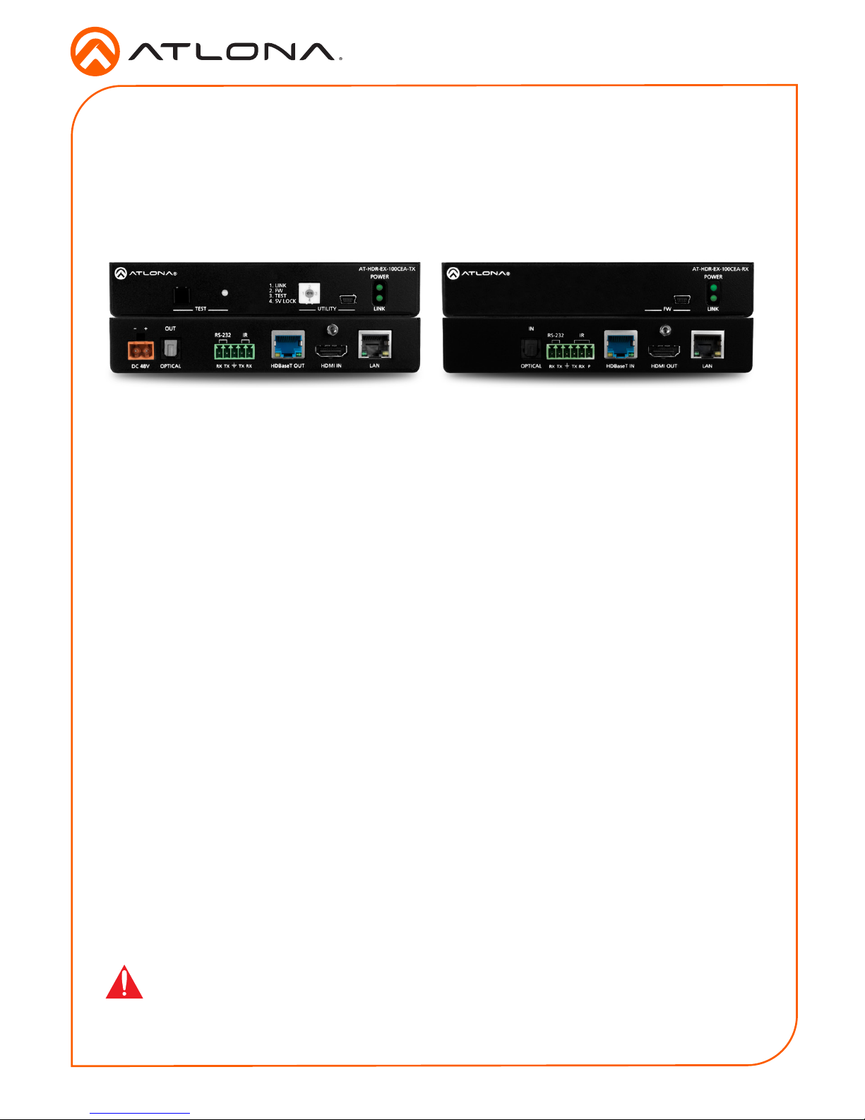
Package Contents
1 x AT-HDR-EX-100CEA-TX
1 x AT-HDR-EX-100CEA-RX
4 x Mounting brackets
8 x Mounting screws
1 x 48V DC power supply
1 x IR emitter
1 x 5-pin captive screw connector
1 x 6-pin captive screw connector
1 x Installation Guide
2
Installation Guide
AT-HDR-EX-100CEA-KIT
LAN
HDMI OUTHDBaseT IN
TX TX RXRX P
IRRS-232
IN
OPTICAL
DC 48V HDMI IN LANHDBaseT OUTOPTICAL
TX TX RXRX
-
+
OUT
IRRS-232
POWER
LINKTEST
AT-HDR-EX-100CEA-TX
1. LINK
2. FW
3. TEST
4. 5V LOCK
UTILITY
POWER
LINK
AT-HDR-EX-100CEA-RX
FW
LAN
HDMI OUTHDBaseT IN
TX TX RXRX P
IRRS-232
IN
OPTICAL
POWER
LINK
AT-HDR-EX-100CEA-RX
FW
POWER
LINKTEST
AT-HDR-EX-100CEA-TX
1. LINK
2. FW
3. TEST
4. 5V LOCK
UTILITY
POWER
LINK
AT-HDR-EX-100CEA-RX
FW
POWER
LINK
AT-HDR-EX-100CEA-RX
FW
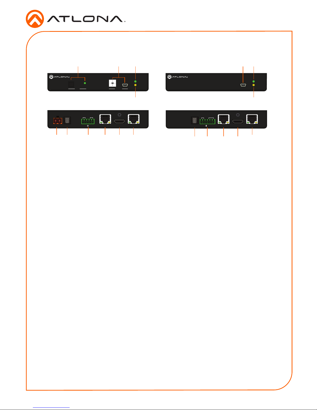
Panel Descriptions
1 TEST
Press this button to test the integrity of the
HDBaseT cable. Refer to Testing HDBaseT
Signal Integrity (page 8) for more
information.
2 UTILITY
Connect a mini-USB to USB-A cable from this
port to a computer. Refer to Utility Switch (page
9) for more information on this feature.
3 POWER
This LED indicator glows solid green when the
unit is powered. Refer to LED Indicators (page
7) for more information.
4 LINK
This LED indicator glows solid amber when a
solid link is established between the transmitter
and receiver. Refer to LED Indicators (page
7) for more information.
5 DC 48V
Connect the included 48V DC power supply to
this power receptacle.
6 OPTICAL OUT
Connect a digital audio cable from this
TOSLINK™ port to an AV receiver. Outputs
audio as part of the Audio Return Channel
(ARC).
7 RS-232 / IR
Connect the included 5-pin captive screw block
to this receptacle. Refer to RS-232 / IR Wiring
(page 3) for more information.
8 HDBaseT OUT
Connect an Ethernet cable from this port to the
HDBaseT IN port on the receiver.
9 HDMI IN
Connect an HDMI cable from this port to a UHD/
HD source.
10 LAN
Connect an Ethernet cable from this port, on
either the transmitter or receiver, to the network.
Do not connect both LAN ports to the same
network.
11 FW
Connect a mini-USB cable from this port to
update the rmware. Refer to Updating the
Firmware (page 10) for more information.
12 POWER
This LED indicator glows solid green when the
unit is powered.
13 LINK
This LED indicator glows solid amber when a
solid link is established between the transmitter
and receiver. Refer to LED Indicators (page
7) for more information.
14 OPTICAL IN
Connect a digital audio cable from the
TOSLINK™ port on the display to this port.
This port serves as the input for the Audio
Return Channel (ARC), receiving audio from the
display and sending it to the transmitter.
15 RS-232 / IR
Connect the included 6-pin captive screw block
to this receptacle. Refer to RS-232 / IR Wiring
(page 3) for more information.
16 HDBaseT IN
Connect an Ethernet cable from this port to the
HDBaseT OUT port on the transmitter.
17 HDMI OUT
Connect an HDMI cable from this port to an
UHD/HD display.
Front Front
Rear
Rear
Tx Rx
5
1486159716 17
10 10
2 3 12111
4 13
3
Installation Guide
AT-HDR-EX-100CEA-KIT
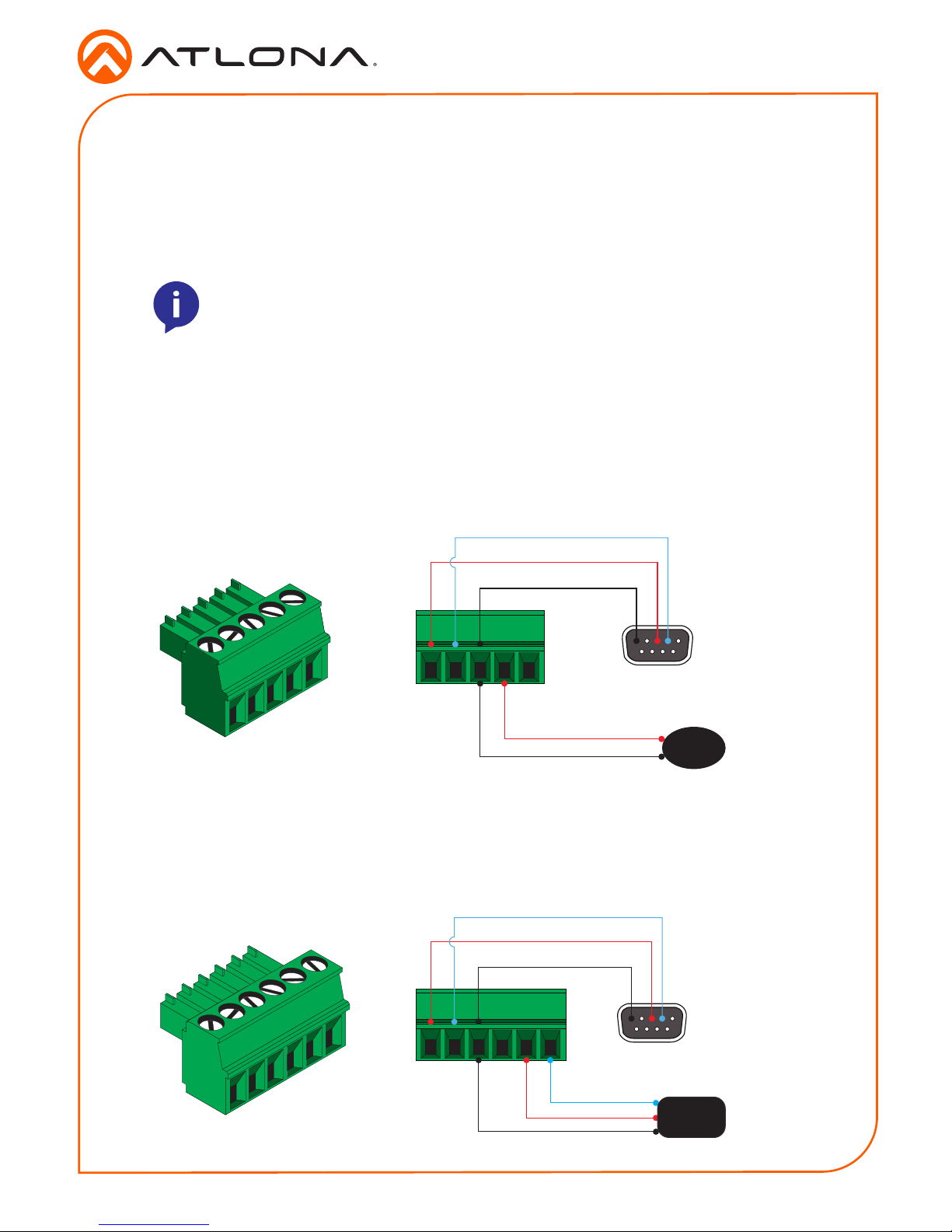
The AT-HDR-EX-100CE-KIT provides both an RS-232 and IR port. RS-232 pass-through is
supported, allowing a control system to be connected to either the transmitter or receiver.
Connect the included IR emitter to the transmitter and an IR extender (not included) to the
receiver. Both IR and RS-232 connections are optional.
1. Use wire strippers to remove at least 3/16” (5 mm) of the cable jacket for both the RS-232
and IR emitter.
2. Insert the wires as shown into the included 5-pin captive screw connector.
1. Use wire strippers to remove at least 3/16” (5 mm) of the cable jacket for both the RS-232
and IR emitter.
2. Insert the wires as shown into the included 6-pin captive screw connector.
NOTE: Typical DB9 connectors use pin 2 for TX, pin 3 for RX, and pin 5 for
ground. On some devices functions of pins 2 and 3 are reversed. Also note, that
IR is bidirectional, allowing the IR emitter or IR receiver to be connected to either
the transmitter or receiver.
RS-232 / IR Wiring
GND
RX
TX
S
G
IR Emitter
DB-9 Connector
GND
RX
TX
S
P
G
IR Receiver
DB-9 Connector
Transmitter
Receiver
4
Installation Guide
AT-HDR-EX-100CEA-KIT
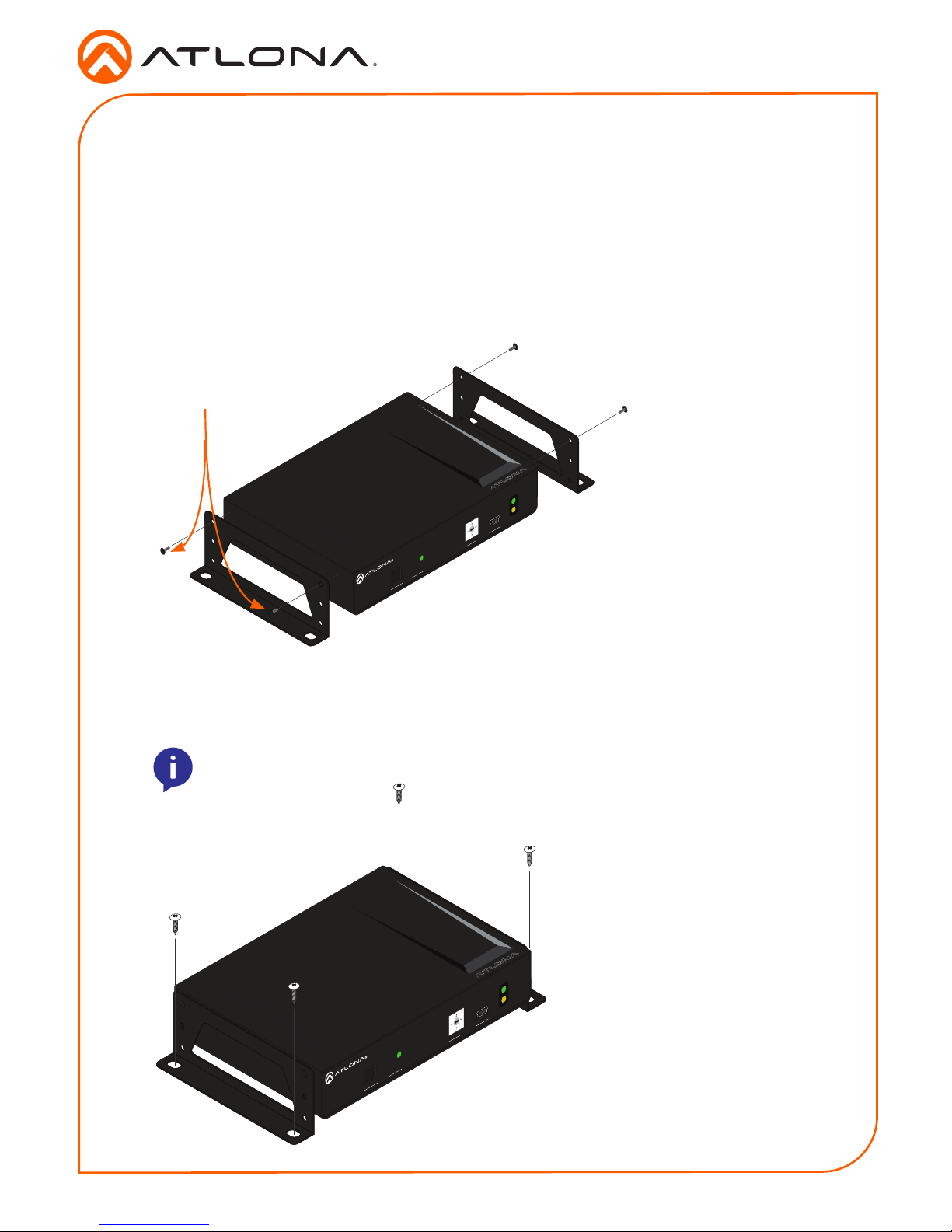
The AT-HDR-EX-100CEA-KIT includes two mounting brackets and four mounting screws each,
which can be used to attach the units to any at surface.
1. Position one of the mounting brackets, as shown below, aligning the holes on the side of the
enclosure with one set of holes on the mounting bracket.
2. Use the enclosure screws to secure the mounting bracket to the enclosure.
3. Repeat the above steps to attach the second mounting bracket to the opposite side of the
unit.
Mounting Instructions
POWER
LINKTEST
AT-HDR-EX-100CEA-TX
1. LINK
2. FW
3. TEST
4. 5V LOCK
UTILITY
Included screws
4. Mount the unit using the oval-shaped holes, on each mounting bracket. If using a drywall
surface, a #6 drywall screw is recommended.
NOTE: Mounting brackets can also be inverted to mount the unit under a table
or other at surface.
POWER
LINKTEST
AT-HDR-EX-100CEA-TX
1. LINK
2. FW
3. TEST
4. 5V LOCK
UTILITY
 Loading...