

Atlona AT-GAIN-60, Gain 60 Installation Manual
1
Installation Guide
AT-GAIN-60
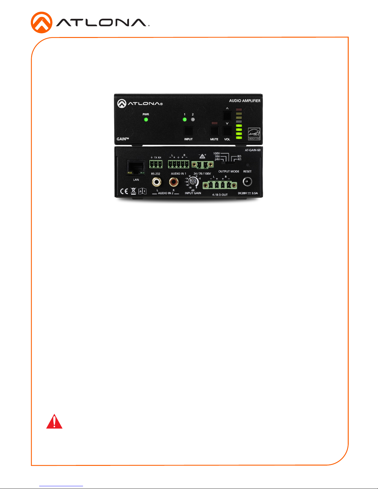
Stereo / Mono Audio Power Amplier - 60 Watts
AT-GAIN-60
1 x AT-GAIN-60
1 x Captive screw connector, 2-pin
1 x Captive screw connector, 3-pin
1 x Captive screw connector, 4-pin
1 x Captive screw connector, 5-pin
1 x 28 V / 3.4 A DC power supply
1 x Installation Guide
Package Contents
The Atlona Gain™ 60 (AT-GAIN-60) is a compact power amplier designed for low or high
impedance applications. A mode selector switch allows the Gain 60 to deliver two channels
of 30 watts each into 4 or 8 ohms, or a single channel of 60 watts at 24, 70,or 100 volts.
This Class-D amplier is energy ecient and convection-cooled without the need for fans.
Additionally, the Gain 60 is UL 2043 plenum-rated, allowing convenient yet discreet installation
in a plenum airspace above a drop ceiling. Selectable balanced captive screw and unbalanced
RCA inputs are provided for system design versatility. The Gain 60 is controllable via TCP/
IP or RS-232, and can be integrated with Atlona AV switchers, HDBaseT™ receivers, and
OmniStream™ AV decoders and audio devices for a wide variety of sound reinforcement
applications.
IMPORTANT: Visit http://www.atlona.com/product/AT-GAIN-60 for the latest rmware
updates and User Manual.
2
Installation Guide
AT-GAIN-60
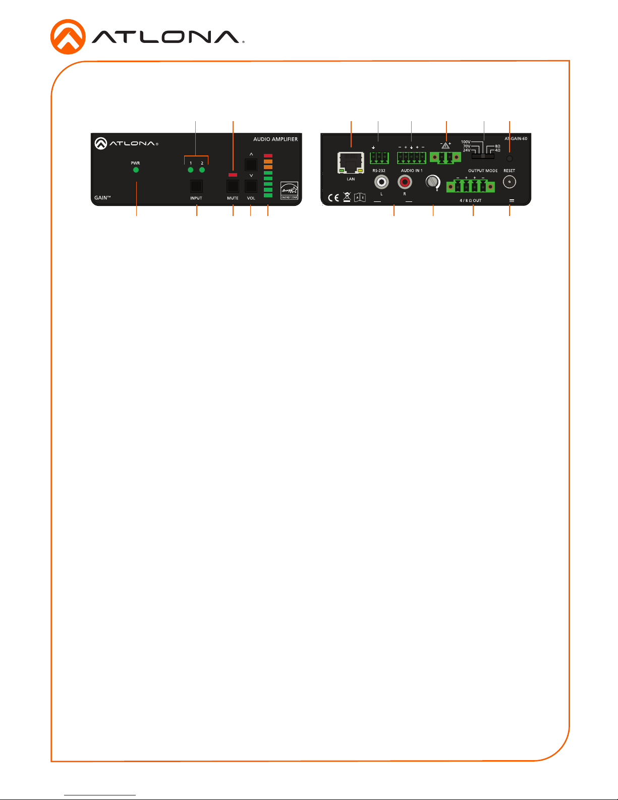
Panel Description
DC28VAUDIO IN 2
INPUT GAIN
L R
L
TX RX
R
3.4A
-22
-2
-4
-20
-19
-14
-9
CLASS 2 WIRING
24 / 70 / 100V OUT
CLASS 2 WIRING
dB
1 PWR
This LED indicator glows solid green when
the unit is powered. When set to standby
mode, this LED indicator glows solid
amber.
2 1 / 2
These LED indicators display the currently
selected input. The active input will be
indicated by a solid green LED.
3 INPUT
Press this button to select the desired
audio input.
4 Mute LED Indicator
This LED indicator will glow solid red
when the audio output is muted.
5 MUTE
Press this button to mute the audio
output. Press the button again to unmute
the audio output.
6 VOL
Press these buttons to adjust the output
volume. Press the top button to increase
volume; press the bottom button to
decrease the volume.
7 Audio Output Indicator
Displays the output audio level. If the
volume level peaks at the red indicator
(0 dB), then clipping will occur.
8 LAN
Connect an Ethernet cable from this port
to the Local Area Network.
9 RS-232
Connect the included 3-pin captive screw
connector from this port to an RS-232
controller or automation system.
10 AUDIO IN 2 (unbalanced)
Connect RCA cables, from an analog line
input, to these ports. Both analog stereo
or two mono connections are supported.
Input impedance is 10 kΩ.
11 AUDIO IN 1
Connect the included captive screw
connector, from a balanced / unbalanced
analog line output, to this port. Input
impedance is 20 kΩ.
12 INPUT GAIN
Turn this pot to adjust the audio input gain
in 4 dB increments.
13 24 / 70 / 100V
Connect the included 2-pin captive screw
connector from this port to a distributed
speaker system. Before connecting the
speakers, set the speaker voltage using
the OUTPUT MODE switch.
14 4 / 8 Ω OUT
Connect the included 4-pin captive screw
connector from this port to a pair of
program / stereo speakers.
Before connecting the speakers, set the
speaker impedance using the OUTPUT
MODE switch.
15 OUTPUT MODE
Slide this switch to set the correct speaker
impedance or voltage setting.
16 RESET
Press this button to reset the unit to
factory-default settings.
17 DC 28V
Connect the included 28 V DC locking
power supply to this power receptacle.
Front Rear
1 3 5 6 7 10 12 14 17
2 4 8 9 11 13 15 16
3
Installation Guide
AT-GAIN-60
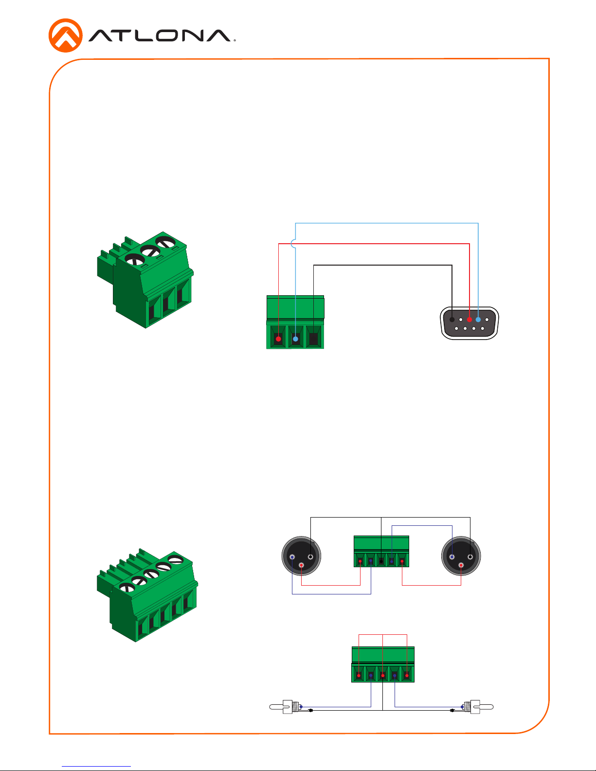
RS-232 Connector
Analog Audio Input Connector
The AT-GAIN-60 provides RS-232 control between an automation system and an RS-232 device.
This step is optional.
1. Use wire strippers to remove a portion of the cable jacket.
2. Remove at least 3/16” (5 mm) from the insulation of the RX, TX, and GND wires.
3. Insert the TX, RX, and GND wires into correct terminal on the included captive screw block.
GND
RX
TX
5 3 2
The AUDIO IN 1 connector on the AT-GAIN-60 provides the ability to connect either balanced or
unbalanced audio inputs, using the included 5-pin captive screw block.
Balanced audio connections use two signal wires and a ground to minimize interference in audio
signals. Unbalanced audio connections use one signal wire and a ground and are used if system
components don’t support balanced signals.
2 1
3
2 1
3
GND GND
-
+
Rear View
Rear View
-
+
GND
Side View Side View
-
+
GND
+
-
Balanced Audio using XLR Connectors
Unbalanced Audio using RCA Connectors
4
Installation Guide
AT-GAIN-60
Installation
1. Connect an analog audio source to the AUDIO IN ports. Once connected, press the INPUT
button on the front panel, to switch between the RCA and the 5-pin captive screw port.
• RCA cables (unbalanced)
Connect shielded RCA-type cables from the audio source to the AUDIO IN 2 left/right
RCA jacks.
• Balanced/Unbalanced
Connect the included 5-pin captive screw to the AUDIO IN 1 port. Use the desired
wiring conguration, on the previous page.
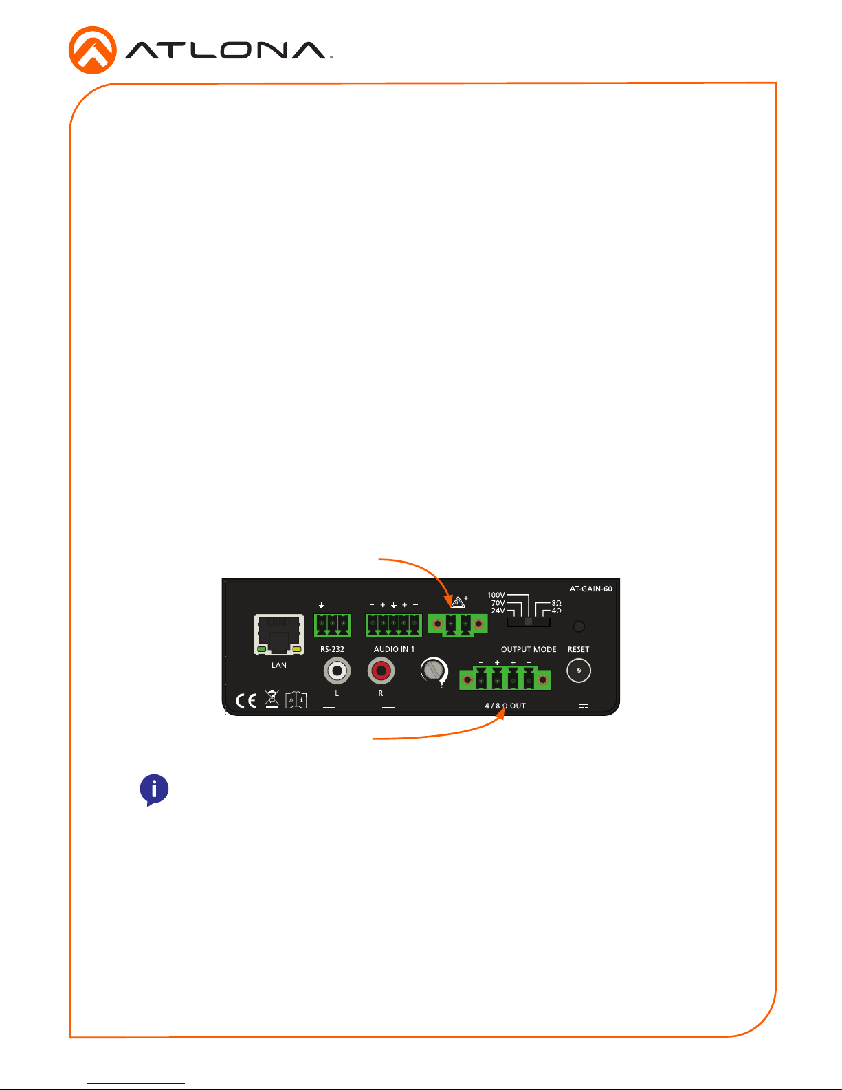
2. Determine the use-case scenario of the AT-GAIN-60. The AT-GAIN-60 can be congured as
either one of the following. Only one type of speaker connection is permitted at a time.
• Distributed speaker system (high impedance)
Set the OUTPUT MODE switch to the required voltage setting: 24V, 70V, or 100V.
This mode is used for commercial applications and longer speaker cable runs.
• Program speakers / stereo (low impedance)
Set the OUTPUT MODE switch to the impedance setting of the speakers being
connected: 4Ω or 8Ω. This mode is used for consumer applications and shorter
speaker cable runs.
Refer to Connection Diagrams (page 7) for example applications.
3. Connect the speakers to the proper port on the AT-GAIN-60, based on the selection made
in the previous step.
4. Connect the LAN port to a network switch for set up and control of the unit.
5. Connect the included power supply to the DC 28V power receptacle.
6. Connect the IEC power cable to an available electrical outlet.
NOTE: The AT-GAIN-60 only supports one type of speaker connection at a time:
high-impedance or low-impedance.
DC28VAUDIO IN 2
INPUT GAIN
L R
L
TX RX
R
3.4A
-22
-2
-4
-20
-19
-14
-9
CLASS 2 WIRING
24 / 70 / 100V OUT
CLASS 2 WIRING
dB
Distributed speakers (high-Z)
Program / stereo speakers (low-Z)
 Loading...