

Page 1
AtlonA
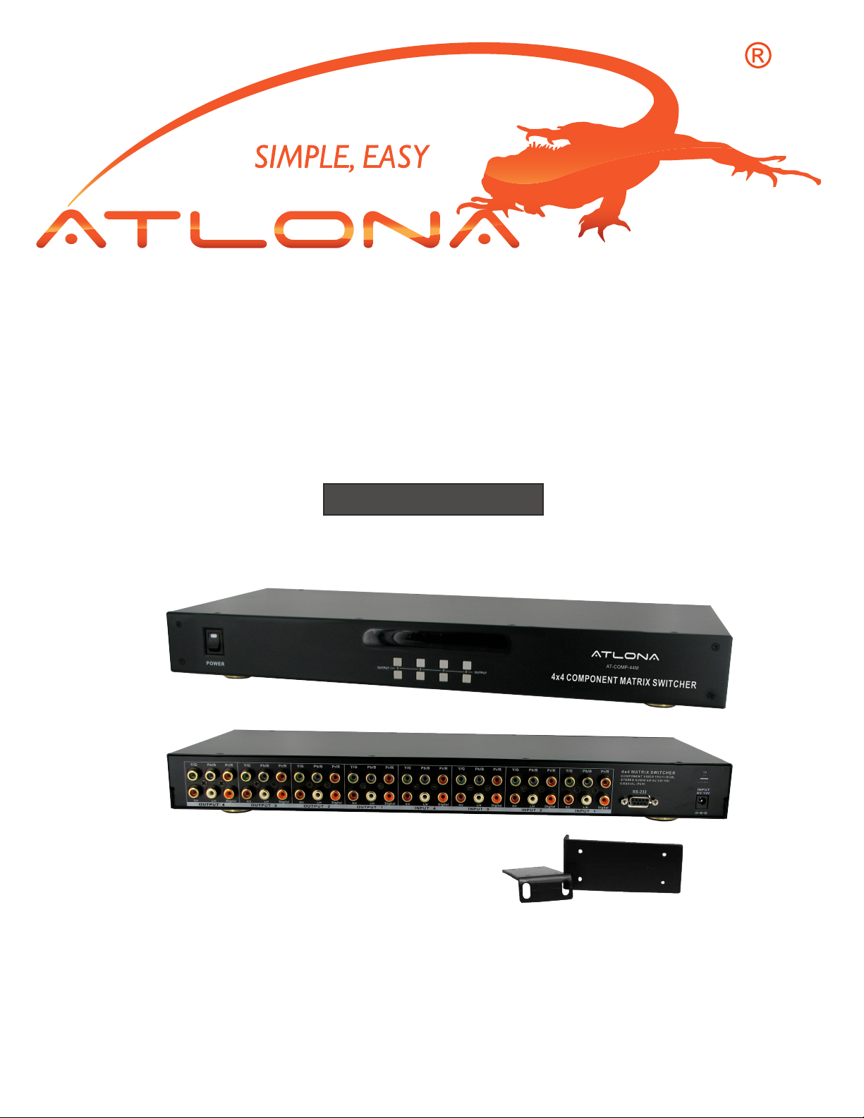
4x4 Component Matrix Switcher
with Stereo Audio
AT-COMP-44M
User Manual
Page 2

TABLE OF CONTENTS
1. Introduction .................................................. 1
2. Features .................................................. 1
3. Package Contents .................................................. 1
4. Specications .................................................. 2
5. Panel Descriptions .................................................. 2
5.1 Front Panel .................................................. 2
5.2 Rear Panel .................................................. 3
6. Remote Control .................................................. 4
7.RS232 Serial Interface .................................................. 5
7.1. Connect a PC or Control System .................................................. 5
7.2. RS232 .................................................. 5
7.3. Protocol Commands .................................................. 5
8. RS232 Serial Commands .................................................. 6
8.1. Power Off Mode .................................................. 6
8.2. Front Panel Lock .................................................. 6
8.3. Unit Reset .................................................. 6
9. Typical Application .................................................. 7
10. Installation .................................................. 8
11. Safety Information .................................................. 9
12. Warranty .................................................. 10
13. Atlona Product Registration .................................................. 11
Page 3

INTRODUCTION
Atlona Technologies’ AT-COMP-44M is one of the most innovative Component Matrix switchers
with Stereo Audio on the market. The AT-COMP-44M has 4 individual Component Video (RCA)
inputs with Audio and 4 individual outputs. Because it is a matrix switch, any input can
route to any output; and the same input can route to all outputs or any other combination. This unit
is ideal for connecting sources including: (VCRs, Camcorders, Video Game Consoles, DVDs,
Satellite Receivers, Set Top Boxes, etc.) to desired displays such as: (HDTV, LCDs, Plasma
Monitors, Video Projectors, etc.) Selection of inputs can be achieved manually through the Front
Panel, an Infrared Remote Control unit or RS232 control. Easily Switch with awless and
crystal-clear distribution of all HDTV video formats up to 1080p as well as audio signals. With
these attributes, the AT-COMP-44M is a great matrix switch capable of handling High Denition
Television applications.
FEATURES:
• 4 inputs to 4 outputs Component Video (Matrix Switcher)
• Supported Signals:
Component Video: YPBPR
Digital: (PCM)
Audio : Stereo Audio (Audio Right/Audio Left)
• Support RS 232 interface
• Control Through IR remote control and Manually via Front Panel Buttons
• Video Bandwidth: 325MHz
• Resolutions: 480p, 576p, 720p, 1080i, 1080p
• Supports 50Hz or 60Hz ( PAL/NTSC )
• Included 19 inch Ear mounts
• Power supply DC12Volt, Universal Type Switch 100~230VAC, 50/60Hz
PACKAGE CONTENTS:
• AT-COMP-44M Matrix Switcher x 1.
• Instruction Manual x 1
• IR Remote Controller
• RS 232 Drive CD x 1
• Universal AC Adaptor : 12VDC
• 19in. Rack Mount ears ( pair ) x 1
Page 4
SPECIFICATIONS
Type of Switcher 4 input to 4 output, Component Video/Digital Audio Matrix Switch
I/O Signals Component Video (YPBPR) 0.5~1.0Vpp, DDC 5Vpp,
Digital Coaxial Audio, 1x RCA connector
Stereo Audio, 2x RCA connectors (Red/white)
Video Bandwidth 325MHz (-3db), 200mVp-p
Video Supported High Resolution formats 480i/p, 720p & 1080i/p
Audio Supported Digital Audio (PCM) and Stereo Audio
Low all hostile crosstalk -83 db@5MHz
Controls IR remote, Select buttons on the front panel & RS232
PC RS232 Control RS232 interface serial via DRV on a PC
Gain control 60MHz 0.1 db gain atness
Safety Approvals CE, FCC, RoHS(2002/95/EC)
Dimensions (LWH) 19” x 7.87” x 1.73”(482mm x 200mm x 44mm)
Power Supply 12V DC. Use Universal Switch Type 50/60Hz,100~230 VAC
Shipping Weight 2.45 Kgs / 4.08 lb
PANEL DESCRIPTIONS
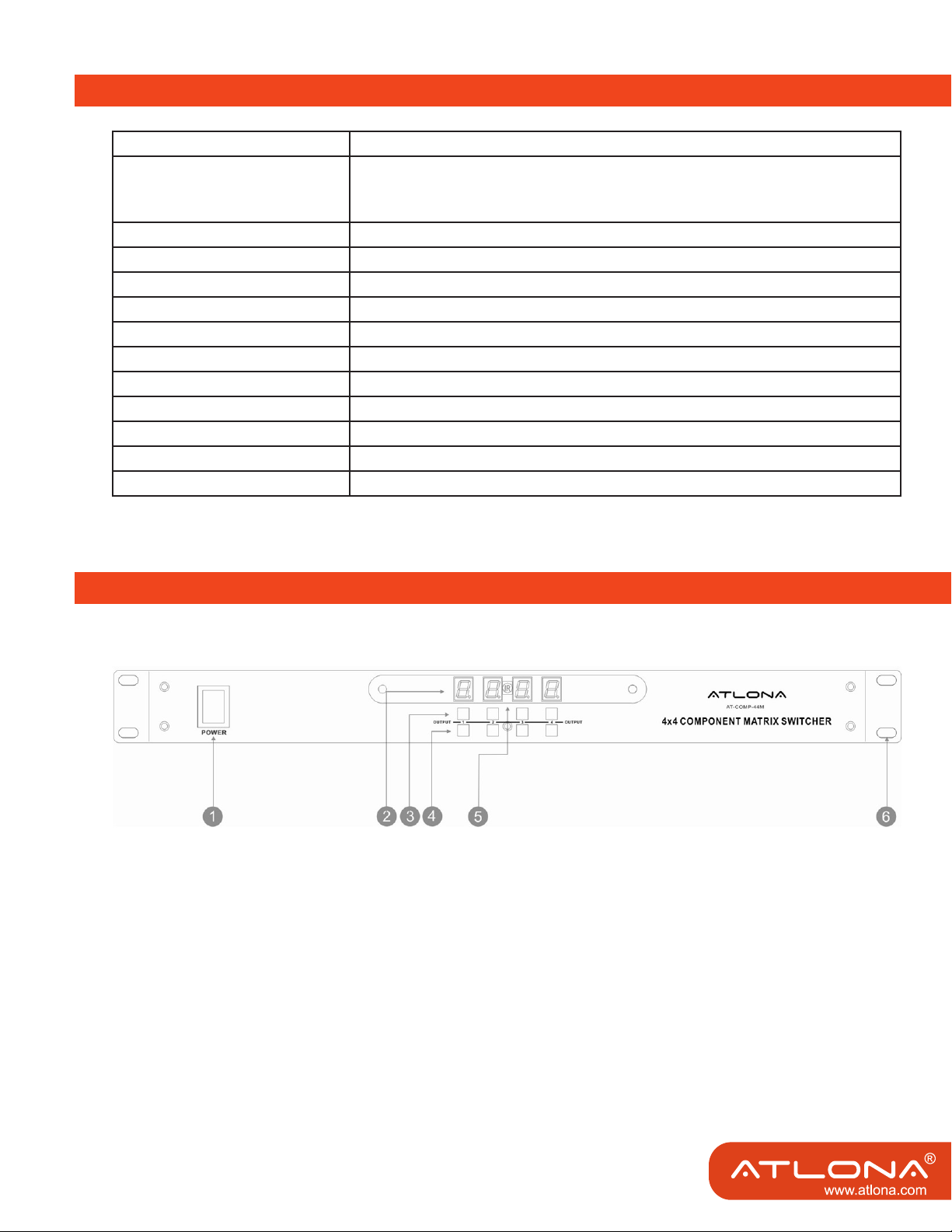
1. Front Panel
1. Power Switch: Powering Unit ON/OFF. The LED will illuminate red to indicate that the switcher is ON
2. Output LED Display: Displays Output in use with correspond Input. The LED will illuminate red to indi
cate that desired video source is present on that input.
3. & 4. Input Select Buttons: Push to select desired Inputs
5. IR Sensor. Receives IR commands from the remote controller
6. 19in Ear Rack Mounts
2
Page 5

2. Rear Panel
1. 12V DC Power Input The AT-COMP-44M is tted with a DC power plug- input park connector
Power Jack:
DC Jack - inner OD O 2.1mm (+ )
Outside OD O 5.5mm (GND)
2. RS 232 Connection. RS 232 control port allows for interfacing to a PC such as a computer or touch
panel control, to the AT-COMP44M via DB-9pin Female connector for serial RS-232 control
3. Inputs: 1-4 Component/Digital Audio.
Component Video (3xRCA's)
Digital Coaxial Audio (1x RCA connector)
Stereo Audio (2x RCA connectors)
4. Outputs: 1-4 Component/Digital Audio.
Component Video (3x RCA's)
Digital Coaxial Audio (1x RCA connector)
Stereo Audio (2x RCA connectors)
Page 6

REMOTE CONTROL
Before making any connections to the AT-COMP-44M Observe the following:
Mains voltage supply must matches the label on the supplied plug-Pack (+/- 10%)
Power switch is OFF
All system grounds (earth) must be connected to a common point.
Avoid powering equipment within a system from multiple power sources that may be separated by large
distances
Connect all audio video sources and destination equipment
Power up all sources
For each destination output select the appropriate input source by usingthe front panel input 1-4 select
buttons, the supplied IR remote control or through the RS 232 serial communications port.
Upon power up, the switcher will return to its last used setting before powered down.
Series Code: 24 DB
1. Power On or Off
Controller with a separate power to turn ON and OFF
2.Outputs1- 4: Output to desired displays
Output -1: TV-1 Component Video (YPBPR) HDTV Display
Output -2: TV-2 Component Video (YPBPR) HDTV Display
Output -3: TV-3 Component Video (YPBPR) HDTV Display
Output -4: TV-4 Component Video (YPBPR) HDTV Display
3.Inputs 1-4: Input Video Source Selections
Input -1: AV-1 Component Video (YPBPR) Signal source device
Input -2: AV-2 Component Video (YPBPR) Signal source device
Input -3: AV-3 Component Video (YPBPR) Signal source device
Input -4: AV-4 Component Video (YPBPR) Signal source device
4
Page 7

RS-232 SERIAL INTERFACE
1. Connect a PC or Control System
Pin RS-232 Denition
1 - Not used
2 TX Transmitter
3 RX Receiver
4 - Not used
5 GND Ground
6 - Not used
7 - Not used
8 - Not used
9 - Not used
2. RS232
The AT-COMP-44M can be controlled via the RS-232 serial control port to allow for interfacing to a PC, or
a similar third party control system.
The serial communication parameters are 9600 baud, 8 bit, No Parity and 1 stop bit - this is often referred
to as 9600 8N1.
When the unit recognizes a complete command it will perform the requested action - there is no delimiter
character required.
The unit does not send out a message when a value is changed from the front panel or by IR control. If the
unit needs to be controlled via the front panel in addition to the RS232 control, you should regularly poll
the unit status to ensure the control system accurately relate the current settings.
3. PROTOCOL COMMANDS
To Switch Inputs to Outputs
SBI0XO0Y- Where X is Output Number (1~4) and Y is Number (1~4)
Unit will respond with
SBUD0XOY - Where X is Output Number (1~4) and Y is Input Number (1~4)
Example : Send Input 4 to Output 3
SBUD04O3-Send
SBI04O03-Rcvd
5
Page 8

RS-232 SERIAL COMMANDS
Note: Turning the unit System Power Off over RS232 will distinguish the LED display leaving only the Power
Switch LED on. The Video and Audio outputs will also mute. While the unit is turned off by RS232 it will
continue to accept and act upon switching commands. For example, if the unit is in the OFF Mode
(via RS232) and you send a command to switch an input to an output, that route will complete and the
video and audio will now appear on that channel only. The front panel LED for that particular output will
also show the input selected (for that single output channel only). The remaining LED’s will remain off
and video and audio outputs muted. The unit will still return status and change messages in response
to commands sent while in Power Off state. A hard reset command (SBALLRST) will return the unit to
normal operation and also unlock the front panel.
1. POWER OFF MODE
SBSYSMOF - Place system into Standby (Soft Power Off)
SBSYSMON - Bring unit out of Standby (Soft Power On)
Unit will respond with
SBALOFAK - Unit is in Standby
SBALONAK - Unit is no longer in Standby
Example : Put Unit in Standby (Soft Power)
SBSYSMOF - Send
SBALOFAK - Rcvd
2. FRONT PANEL LOCK
Note: Hard resetting the unit will unlock the Front Panel controls.
SBSYSMLK - When front panel is locked, changes can only be made by RS232
SBSYSMUK- Front Panel Unlock
Unit will respond with
SBSYSLOK - Front Panel has been Locked
SBSYSULK - Front Panel has been Unlocked
Example : Lock Front Panel Buttons
SBSYSMLK - Send
SBSYSLOK - Rcvd
3. UNIT RESET
SBALLRST - Reset every output to Input 1 Unit will respond with
SBRSTACK - Unit has reset each Output to Input 1
Example : Reset all outputs to Input 1
SBALLRST - Send
SBRSTACK - Rcvd
6
Page 9

TYPICAL APPLICATION
VCR Player
AT-COMP-44M
DVD Player
Satellite Receiver
HD Player
up to 4 Sources
up to 4 HDTV’s
PC RS232 Control
Page 10

INSTALLATION
CONTROL PORTS :
1. IR REMOTE - IR Remote Controller
2. RS 232 Interface - RS 232 interface system
INPUTS 1 - 4 HD SOURCE SIGNALS :
COMPONENT VIDEO - Component Video
DIGITAL - Digital Audio
AUDIO - Stereo Audio
OUTPUT 1 - 4 HDTV DISPLAY SIGNALS :
COMPONENT VIDEO - Component Video
DIGITAL - Digital Audio
AUDIO - Stereo Audio
8
Page 11

SAFETY INFORMATION
Safeguards
To reduce the risk of electric shock, do not
expose this product to rain or moisture.
If the wall plug does not t into your local
power socket, hire an electrician to replace
your obsolete socket.
Do not modify the wall plug.
Doing so will void the warranty and safety
features.
This equipment should be installed near
the socket outlet and the device should
be easily accessible in case it requires
disconnection.
Precautions
FCC Regulations state that any
unauthorized changes or modications to
this equipment not expressly approved by
the manufacturer could void the
user’s authority to operate this
equipment.
Avoid excessive humidity, sudden
temperature changes or temperature
extremes.
Keep this product away from wet locations
such as bathtubs, sinks, laundries, wet
basements and swimming pools.
Use only accessories recommended by
ATLONA to avoid re, shock or other
hazards.
Unplug the product before cleaning. Use
a damp cloth for cleaning. Do not use
cleaning uid or aerosols, which could
enter the unit and cause damage, re or
electrical shock. Some substances may
also mar the nish of the product.
Never open or remove unit panels or make
any adjustments not described in this
manual. Attempting to do so could expose
you to dangerous electrical shock or other
hazards. It may also cause damage to your
AT-COMP-44M. Opening the product will
void the warranty.
Operate this product using only the
included external power supply. Use of
other power supplies could impair
performance, damage the product or cause
res.
In the event of an electrostatic discharge,
this device may automatically turn off. If this
occurs, unplug the device, and plug it back
in.
Protect and route power cords so they will
not be stepped on or pinched by anything
placed on or against them. Be especially
careful of plug-ins, or cord exit points from
this product.
Do not attempt to service the unit. Instead
disconnect it and contact your Authorized
ATLONA reseller or contact ATLONA
directly.
9
Page 12

WARRANTY
1. LIMITED WARRANTY
Atlona Technologies warrants that (a) its products (the “Product”) will perform substantially in accordance with the
accompanying written materials for a period of 3 YEARS from the date of receipt and (b) that the Product will be
free from defects in materials and workmanship under normal use and service for a period of 3 years. In the event
applicable law imposes any implied warranties, the implied warranty period is limited to 3 years from the date of
receipt. Some jurisdictions do not allow such limitations on duration of an implied warranty, so the above limitation
may not apply to Customer.
2. CUSTOMER REMEDIES
Atlona Technologies and its suppliers’ entire liability and Customer’s exclusive remedy shall be, at Atlona Technolo-
gies’ option, either return of the price paid for the Product, or repair or replacement of the Product that does not meet
this Limited Warranty and which is returned to Atlona Technologies with a copy of Customer’s receipt. This Limited
Warranty is void if failure of the Product has resulted from accident, abuse, or misapplication. Any replacement Prod-
uct will be warranted for the remainder of the original warranty period or 3 year, whichever is longer.
3. NO OTHER WARRANTIES
TO THE MAXIMUM EXTENT PERMITTED BY APPLICABLE LAW, ATLONA TECHNOLOGIES AND ITS SUPPLI-
ERS DISCLAIM ALL OTHER WARRANTIES, EITHER EXPRESS OR IMPLIED, INCLUDING, BUT NOT LIMITED
TO IMPLIED WARRANTIES OF MERCHANTABILITY AND FITNESS FOR A PARTICULAR PURPOSE, WITH
REGARD TO THE PRODUCT AND ANY RELATED WRITTEN MATERIALS. THIS LIMITED WARRANTY GIVES
CUSTOMER SPECIFIC LEGAL RIGHTS. CUSTOMER MAY HAVE OTHER RIGHTS DEPENDING ON THE JU-
RISDICTION.
4. NO LIABILITY FOR DAMAGES
TO THE MAXIMUM EXTENT PERMITTED BY APPLICABLE LAW, IN NO EVENT SHALL ATLONA TECHNOLO-
GIES OR ITS SUPPLIERS BE LIABLE FOR ANY DAMAGES WHATSOEVER (INCLUDING WITHOUT LIMITA-
TION, SPECIAL, INCIDENTAL, CONSEQUENTIAL, OR INDIRECT DAMAGES FOR PERSONAL INJURY, LOSS
OF BUSINESS PROFITS, BUSINESS INTERRUPTION, LOSS OF BUSINESS INFORMATION, OR ANY OTHER
PECUNIARY LOSS) ARISING OUT OF THE USE OF OR INABILITY TO USE THIS PRODUCT, EVEN IF ATLONA
TECHNOLOGIES HAS BEEN ADVISED OF THE POSSIBILITY OF SUCH DAMAGES. IN ANY CASE, ATLONA
TECHNOLOGIES’ AND ITS SUPPLIERS’ ENTIRE LIABILITY UNDER ANY PROVISION OF THIS AGREEMENT
SHALL BE LIMITED TO THE AMOUNT ACTUALLY PAID BY YOU FOR THE PRODUCT. BECAUSE SOME JU-
RISDICTIONS DO NOT ALLOW THE EXCLUSION OR LIMITATION OF LIABILITY FOR CONSEQUENTIAL OR
INCIDENTAL DAMAGES, THE ABOVE LIMITATION MAY NOT APPLY TO YOU.
ATLONA
2151 O’toole Ave, Ste D
San Jose CA 95131
Toll Free: 1-877-536-3976
International: 408-954-8782
FAX: 408-954-8792
Website: www.atlona.com
E-MAIL: info@atlona.com
10
Page 13

ATLONA PRODUCT REGISTRATION
Thank you for purchasing this Atlona product — we hope you’ll enjoy it.
We also hope that you’ll take a few moments to register your new purchase. Registration creates an ownership
record if your product is lost or stolen and helps ensure you’ll receive notication of performance issues and rm-
ware updates.
At Atlona, we respect and protect your privacy and assure you that your registration information is completely
secure. Of course, Atlona product registration is totally voluntary and failure to register will not diminish your limited
warranty rights.
To register go to www.atlona.com/registration
 Loading...