

Page 1
ASP-MG24
OWNER'S MANUAL
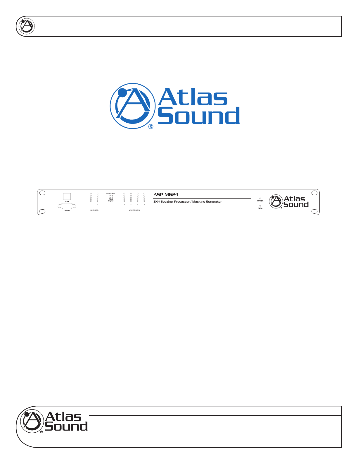
ASP-MG24
2 Input By 4 Output
SIGNAL PROCESSOR / MASKING GENERATOR
www.AtlasSound.com
1601 JACK MCKAY BOULEVARD ENNIS, TEXAS 75119 U.S.A. • TELEPHONE: (800) 876-3333 • FAX: (800) 765-3435
© 2007 ATLAS SOUND LP Printed in U.S.A. ATS002766 RevA 4/07 1
Specifications are subject to change without notice
Page 2
ASP-MG24
ATLAS SOUND ASP-MG24
2 INPUT BY 4 OUTPUT SPEAKER SIGNAL PROCESSOR / MASKING GENERATOR
TABLE OF CONTENTS
1.0 Introduction ............................................................................................. 4
2.0 Features ................................................................................................. 4
3.0 Front Panel Functions ............................................................................ 5
4.0 Rear Panel Functions ............................................................................. 6
5.0 Getting to Know the Software ................................................................. 7
5.1 Loading the Software ............................................................. 7
5.2 Opening the software ............................................................. 7
6.0 Mic / Line Input Section .......................................................................... 8
6.1 Input Meters ........................................................................... 8
6.2 Gain Window .......................................................................... 9
6.3 Compressor Window .............................................................. 9
6.4 Input Filter Window .............................................................. 10
6.5 Input Graph Screen .............................................................. 10
6.6 Input Filter Settings Window ................................................ 10
6.7 Input Crossover Settings Window .........................................11
6.8 Input Graph Sub Screen Window ..........................................11
6.9 Input Mute .............................................................................11
7.0 Masking Section ................................................................................... 12
7.1 Masking Level Meter ............................................................ 12
7.2 Masking Selection Window .................................................. 12
7.3 Masking Auto Ramp Settings ............................................... 12
7.4 Masking Auto Ramp Bypass ................................................ 12
7.5 Masking Gain Window ......................................................... 13
7.6 Masking EQ Window ............................................................ 13
7.7 Masking Graph Window ....................................................... 13
7.8 Masking 1/3rd Octave EQ Window ...................................... 14
7.9 Masking Crossover Window ................................................. 14
7.10 Masking Mute ....................................................................... 15
8.0 Output Section ...................................................................................... 15
8.1 Mixer Window ....................................................................... 15
8.2 Output Filter Window ............................................................ 16
8.3 Output Graphic Screen ........................................................ 16
8.4 Output Filter Window ............................................................ 16
8.5 Output Crossover Window ................................................... 17
8.6 Output Delay Window .......................................................... 17
8.7 Output Gain Window ............................................................ 17
8.8 Output Limiter Window ......................................................... 18
8.9 Output Mute Window ............................................................ 19
8.10 Output Meters ...................................................................... 19
OWNER'S MANUAL
Specifications are subject to change without notice
www.AtlasSound.com
© 2007 ATLAS SOUND LP Printed in U.S.A. ATS002766 RevA 4/07 2
1601 JACK MCKAY BOULEVARD ENNIS, TEXAS 75119 U.S.A. • TELEPHONE: (800) 876-3333 • FAX: (800) 765-3435
Page 3

ASP-MG24
2 INPUT BY 4 OUTPUT SPEAKER SIGNAL PROCESSOR / MASKING GENERATOR
OWNER'S MANUAL
ATLAS SOUND ASP-MG24
TABLE OF CONTENTS (
9.0 File Import & Export .............................................................................. 19
9.1 Master Rese ......................................................................... 20
9.2 File Open ............................................................................. 20
9.3 File Save .............................................................................. 20
9.4 Device File Recall ................................................................ 21
9.5 Device File Store .................................................................. 21
9.6 Import MEQ Data ................................................................. 22
9.7 Sync Progress Window ........................................................ 22
10.0 Specifications ..................................................................................... 23
11.0 Warranty ............................................................................................. 28
contd.)
Specifications are subject to change without notice
www.AtlasSound.com
© 2007 ATLAS SOUND LP Printed in U.S.A. ATS002766 RevA 4/07 3
1601 JACK MCKAY BOULEVARD ENNIS, TEXAS 75119 U.S.A. • TELEPHONE: (800) 876-3333 • FAX: (800) 765-3435
Page 4

ASP-MG24
OWNER'S MANUAL
1.0 INTRODUCTION
The Atlas Sound ASP-MG24 is a 2 input by 4 output digital loudspeaker management system and
masking generator designed for fixed sound installation markets. The ASP-MG24 features the latest in
available technology utilizing a 32-bit (40-bit extended) floating point processors and high performance
24-bit Analog Converters. Both balanced inputs are mic/line selectable along with 4 addition independent
masking generator input sources. Inputs and outputs can be routed or mixed in multiple configurations
to meet even the most complex system designs. Control parameters include I/O levels, delay, polarity,
parametric EQ, crossover selections, 31 band EQ, White/Pink Noise, Auto Ramp, routing, mixing and
compressor/limiters. The ASP-MG24 can be controlled or configured in real time with the intuitive PC GUI,
accessed via the RS-232 or USB interface. Software upgrade for CPU and DSP via PC always keeps the
ASP-MG24 current. Optional masking scheduler and programmable remote control is also available.
2.0 FEATURES
• 2 Mic/Line Inputs and 4 Outputs
• System routing and mixing flexibility
• 4 Independent Random Pink or White Noise Generators
• 8 Parametric Filters for each Input and Output
• Multiple Crossover types up to 48dB
• Full Function Compressor Limiters
• Four 1/3rd Octave Graphic Equalizers for Masking
• User set masking auto ramp
• Precise Level, Polarity and Delay
• Full 5-segment LED’s on every Input and Output
• Storage of up to 30 Program Setups
• Multiple Levels of Security Locks
• Optional Advance Masking Scheduler
• Optional Programmable System Controller
• RS-232 & USB Interface for PC Control and Configuration
• CPU and DSP upgrade via PC
Specifications are subject to change without notice
www.AtlasSound.com
© 2007 ATLAS SOUND LP Printed in U.S.A. ATS002766 RevA 4/07 4
1601 JACK MCKAY BOULEVARD ENNIS, TEXAS 75119 U.S.A. • TELEPHONE: (800) 876-3333 • FAX: (800) 765-3435
Page 5
ASP-MG24
OWNER'S MANUAL
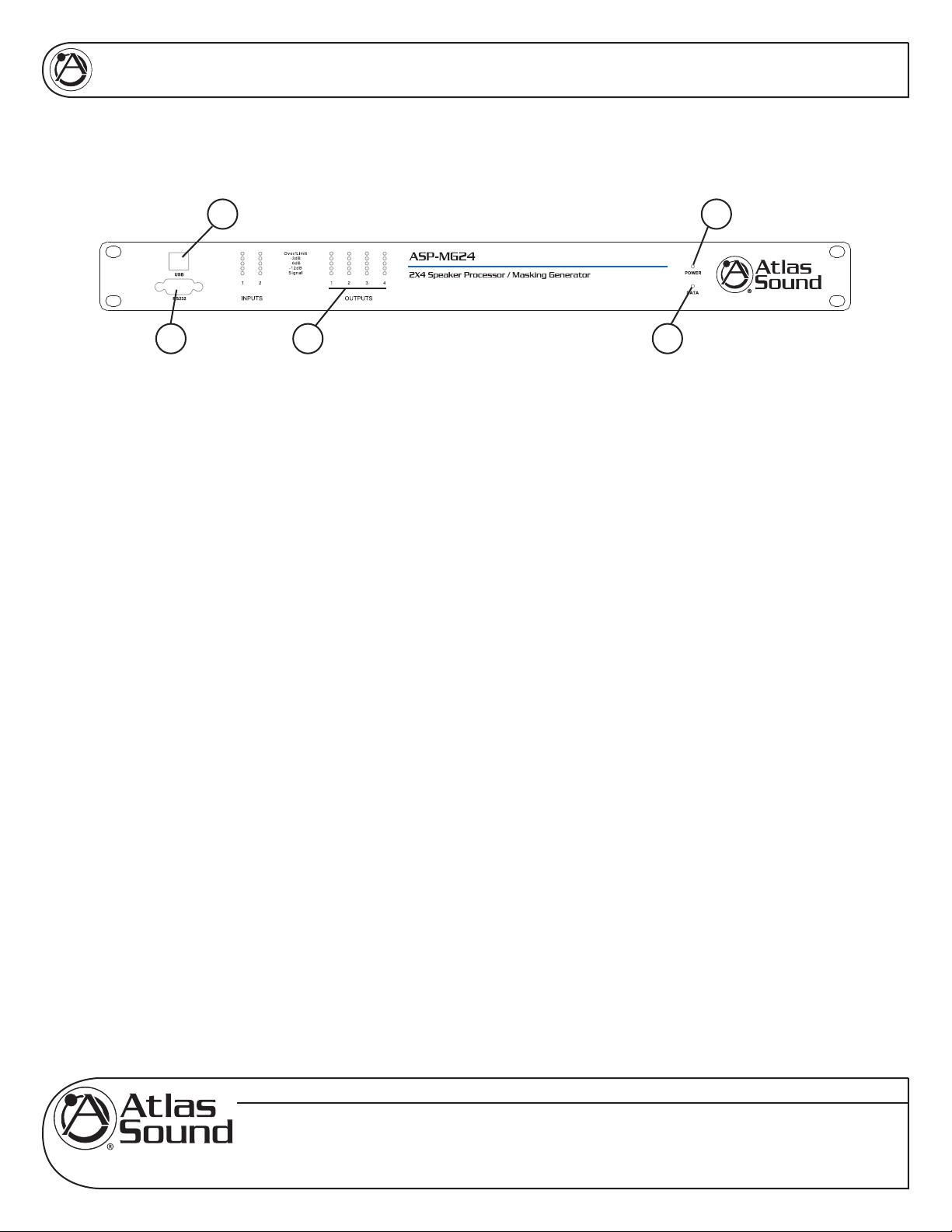
3.0 FRONT PANEL FEATURES
14
3 2 5
1. Power On LED
Illuminates Blue when the external power supply is plugged into the power socket and the power
supply is plugged into a AC source..
2. Level LED
5 LED’s per channel indicates the status of the signal level: Signal, -12dB, -6dB, -3dB, Over/Limit.
The Input “Over” LED references to the device’s maximum headroom. The Output “Limit” LED
references to the threshold of the limiter.
3. RS232 Connector
Standard female DB9 socket. A straight through cable is required for PC connection.
4. USB Connector
Standard female USB socket. A straight through cable is required for PC connection
5. Data LED
This LED will illuminate Green when there is connection made between the ASP-MG24 and the
computer.
Specifications are subject to change without notice
www.AtlasSound.com
© 2007 ATLAS SOUND LP Printed in U.S.A. ATS002766 RevA 4/07 5
1601 JACK MCKAY BOULEVARD ENNIS, TEXAS 75119 U.S.A. • TELEPHONE: (800) 876-3333 • FAX: (800) 765-3435
Page 6
ASP-MG24
OWNER'S MANUAL
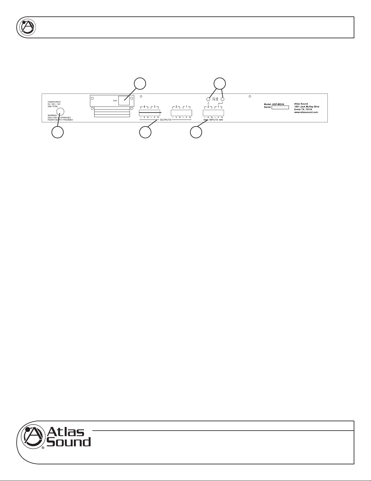
4.0 REAR PANEL FEATURES
35
1 4 2
1. Power Supply Socket
An external UL rated 120v AC power supply has been included with the ASP-MG24. Only use the
provided power supply due to the specific DC voltages required to operate the unit.
2. Input Connectors
There are two removable 3 Pin Phoenix type connectors for providing input signal to the unit. They
can accept either a balanced or unbalanced signal. For balanced signals connect (Ground to GND),
(Positive signal to +) and (Negative signal to -). For unbalanced signals connect the (- to the GND
together) and the Positive to +).
3. Mic / Line Level Selection
Each Input has the capability to accept either a microphone or line level signal. Prior to connecting the
inputs make sure the software input gain that apply to the channel routing are set to -10dB. Also the
limiters are set to +20dB for gain setup. Prior to applying signal to the input you must set the analog
gain switch to match the type of input you are using. The Line position gain is calibrated for 0dBu or
unity gain within the DSP software. The Mic position is calibrated for -30dBu when the DSP gain is set
for unity or 0dB. If more gain is needed carefully turn the up the appropriate channel DSP gain in the
software. If you will be using a microphone it is recommended when starting to turn the input gain to
-40dB and slowly bring up the input gain to the desired level.
4. Output Connectors
There are four removable 3 Pin Phoenix type connectors for providing output signal. They can deliver
either a balanced or unbalanced signal. For balanced signals connect (Ground to GND), (Positive
signal to +) and (Negative signal to -). For unbalanced signals connect the (- to the GND together)
and the Positive to +).
5. RJ45 Port
This port is used for remote system controllers. For Ethernet connection an optional card is required.
Call Atlas for more details.
Specifications are subject to change without notice
www.AtlasSound.com
© 2007 ATLAS SOUND LP Printed in U.S.A. ATS002766 RevA 4/07 6
1601 JACK MCKAY BOULEVARD ENNIS, TEXAS 75119 U.S.A. • TELEPHONE: (800) 876-3333 • FAX: (800) 765-3435
Page 7
ASP-MG24
OWNER'S MANUAL
5.0 GETTING TO KNOW THE SOFTWARE
5.1. Loading the software
1. Load the software onto your computer by following the Quick Star Guide and Software Installation
Guide.
2. Note: It is important to have your computer screen resolution set to the highest viewing
setting or a minimal setting of 1280 x 1240 pixels.
appear out the viewing area. To find a window that should appear use the master screen curser
Up/Down arrows to find the three boxes. All screens can be moved by clicking and holding the
selected screen for personal viewing preferences.
3. After the software is loaded and the proper screen resolution is set. Open the software and follow
the steps below: Note: It is not necessary to have the computer connected to the ASP-MG24
viewing and program purposes.
5.2. Opening the Software
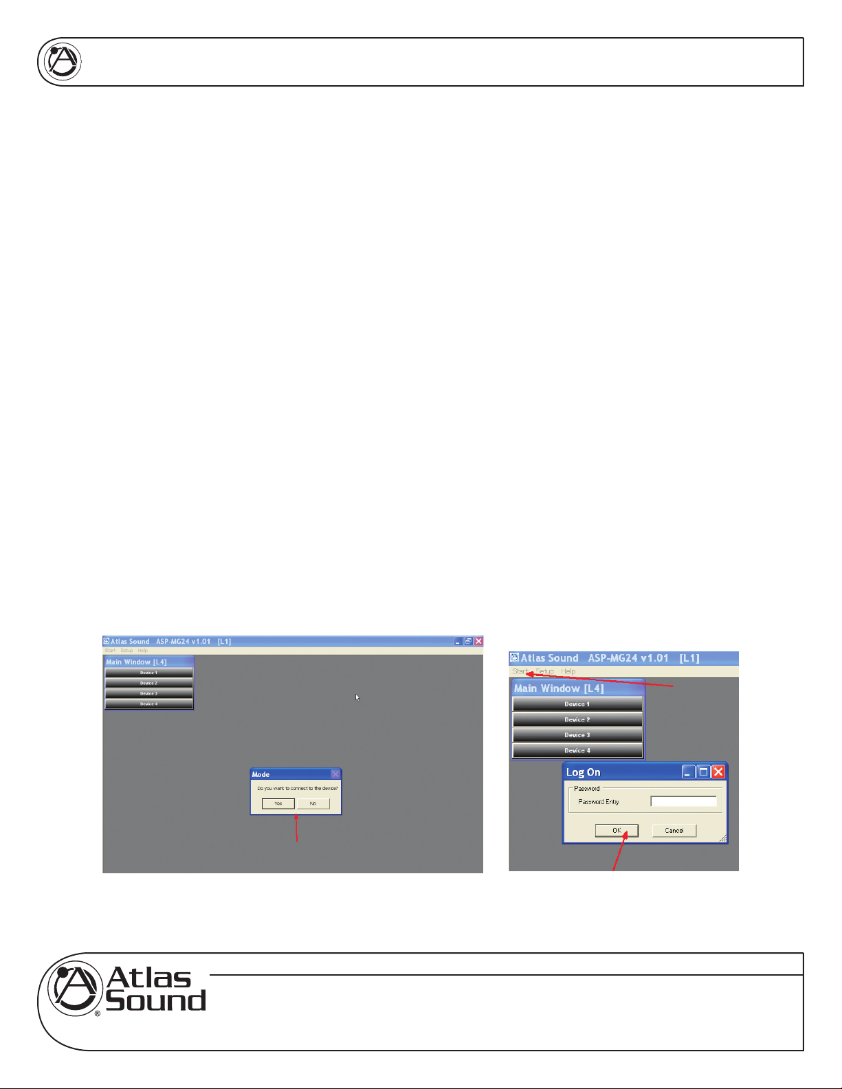
1. Your screen should look like the view below. If not, close the software and restart.
Failure to do may cause the dialog boxes to
2. If you have the ASP-MG24 connected to your computer click “Yes “ to connect or you can work in
Off Line Mode by clicking “NO”.
3. After you have the screen above, click on (1) Start, (2) Log On and then (3) Enter. Do not put
anything into the pass word box at this time. Later you will assign one if needed. If a pass word
has been assigned, you will need to enter it.
Specifications are subject to change without notice
www.AtlasSound.com
© 2007 ATLAS SOUND LP Printed in U.S.A. ATS002766 RevA 4/07 7
1601 JACK MCKAY BOULEVARD ENNIS, TEXAS 75119 U.S.A. • TELEPHONE: (800) 876-3333 • FAX: (800) 765-3435
Page 8
ASP-MG24
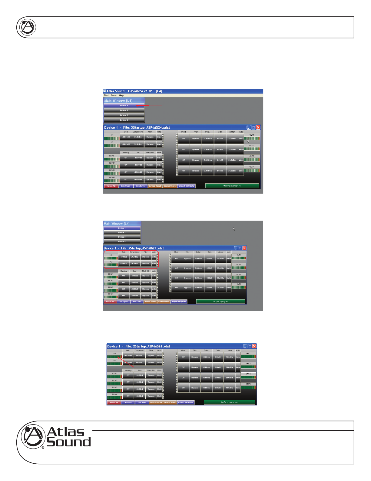
You are now ready to open the Device panel by clicking on Device 1. Note: An ASP-MG24 is also
known as a “Device”. Multiple ASP-MG24’s can be controlled via one GUI interface. If only one
ASP unit is connected to the computer click on Device 1 and the main control window will appear.
OWNER'S MANUAL
6.0 MIC / LINE INPUT SECTION
6.1 Input Meter - The bar graph meter illustrates the level of the input signal POST the channels gain control
and is PRE input filters and compressor settings.
Specifications are subject to change without notice
www.AtlasSound.com
© 2007 ATLAS SOUND LP Printed in U.S.A. ATS002766 RevA 4/07 8
1601 JACK MCKAY BOULEVARD ENNIS, TEXAS 75119 U.S.A. • TELEPHONE: (800) 876-3333 • FAX: (800) 765-3435
Page 9
ASP-MG24
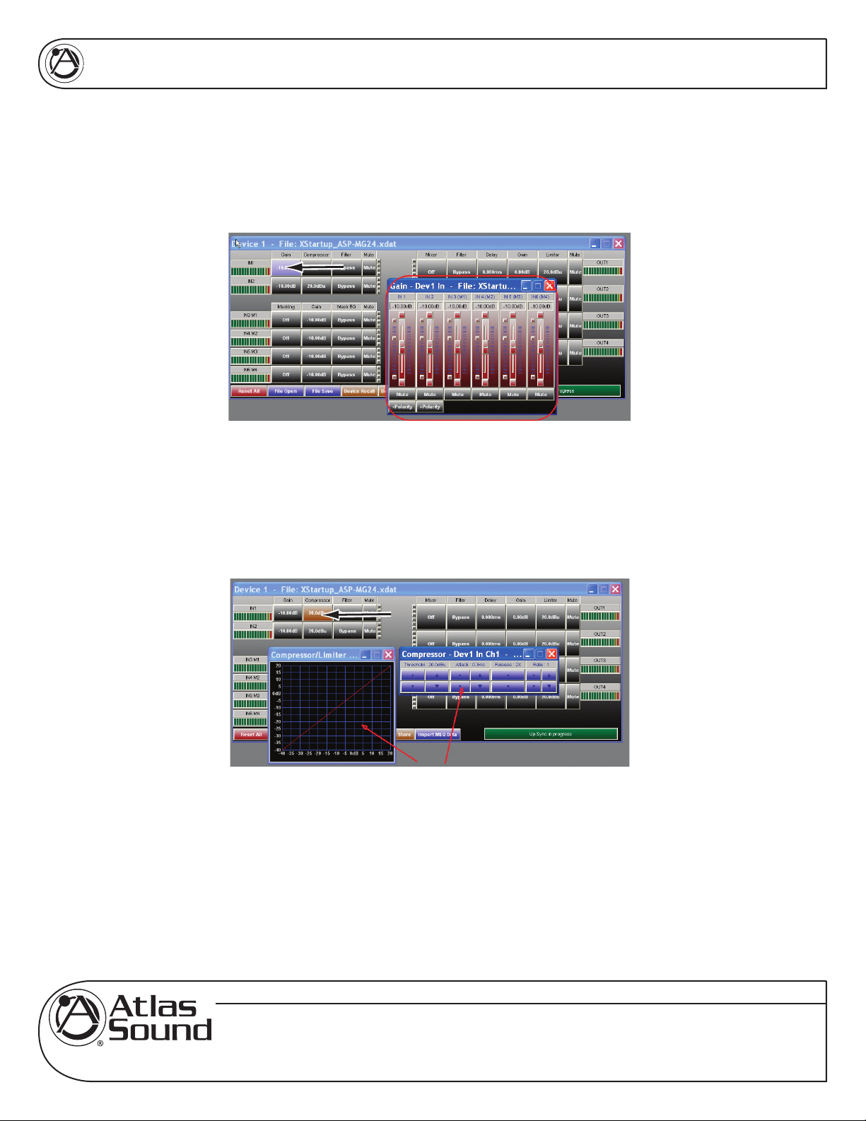
6.2 Gain – For you convenience both Mic / Line Inputs and the four masking generators levels are shown.
Controlling the gain can be accomplished by dragging the fader, using the up down buttons or by typing in the
number viewing text box. Channel Mute can be accomplished by clicking on the Mute tab and will illumination
Red indicating the channel is in Mute. Input Polarity can be set by clicking on the Polarity tab.
6.3 Compressor – Inputs 1 & 2 have fully adjustable compressor limiters. When clicking on the compressor
tab, two sub viewing screens will appear. Note: All control boxes can be dragged for desired positioning of the
screen. Screen 1 is an indicator screen showing the compressor / limiter operation. The second is the settings
screen. In that screen you have control over Threshold, Attack, Release and Ratio. Adjustment can be made
using the Up / Down arrows or by typing into the data viewing text box.
OWNER'S MANUAL
• THRESHOLD - Limit Threshold. Ranges from -20 to +20dBu in 0.5dB steps.
• ATTACK - Attack time. Ranges from 0.3 to 1ms in 0.1ms steps, and ranges from 1 to
100ms in 1ms steps.
• RELEASE - Release time. Can be set at 2X, 4X, 8X, 16X or 32X the attack time.
• RATIO – The Ratio control allows adjustment to the amount of Input vs. Output level with
signals exceeding the set threshold limit.
Specifications are subject to change without notice
www.AtlasSound.com
© 2007 ATLAS SOUND LP Printed in U.S.A. ATS002766 RevA 4/07 9
1601 JACK MCKAY BOULEVARD ENNIS, TEXAS 75119 U.S.A. • TELEPHONE: (800) 876-3333 • FAX: (800) 765-3435
Page 10

ASP-MG24
6.4 Filter - When clicking on the filter screen 3 sub viewing screens appear. Note: If the screens do not appear
you may have to change your screen resolution. Also use the screen curser Up/Down arrows to find the
three boxes. All three screens can be moved by clicking and holding the selected screen for personal viewing
preferences.
OWNER'S MANUAL
6.5 Graphic Screen – This screen will view all the all filter chacteristics that are set.
6.6 Filter Adjust Window – Each input has 8 adjustable filter selections. Choices are Parametric, Hi-shelf and
Lo-shelf. Adjustments can be made via the up / down arrows, text window and by dragging the curser on the
Graphics Screen. After any adjustment made they should appear on the Graphic Screen.
Specifications are subject to change without notice
www.AtlasSound.com
© 2007 ATLAS SOUND LP Printed in U.S.A. ATS002766 RevA 4/07 10
1601 JACK MCKAY BOULEVARD ENNIS, TEXAS 75119 U.S.A. • TELEPHONE: (800) 876-3333 • FAX: (800) 765-3435
Page 11
ASP-MG24
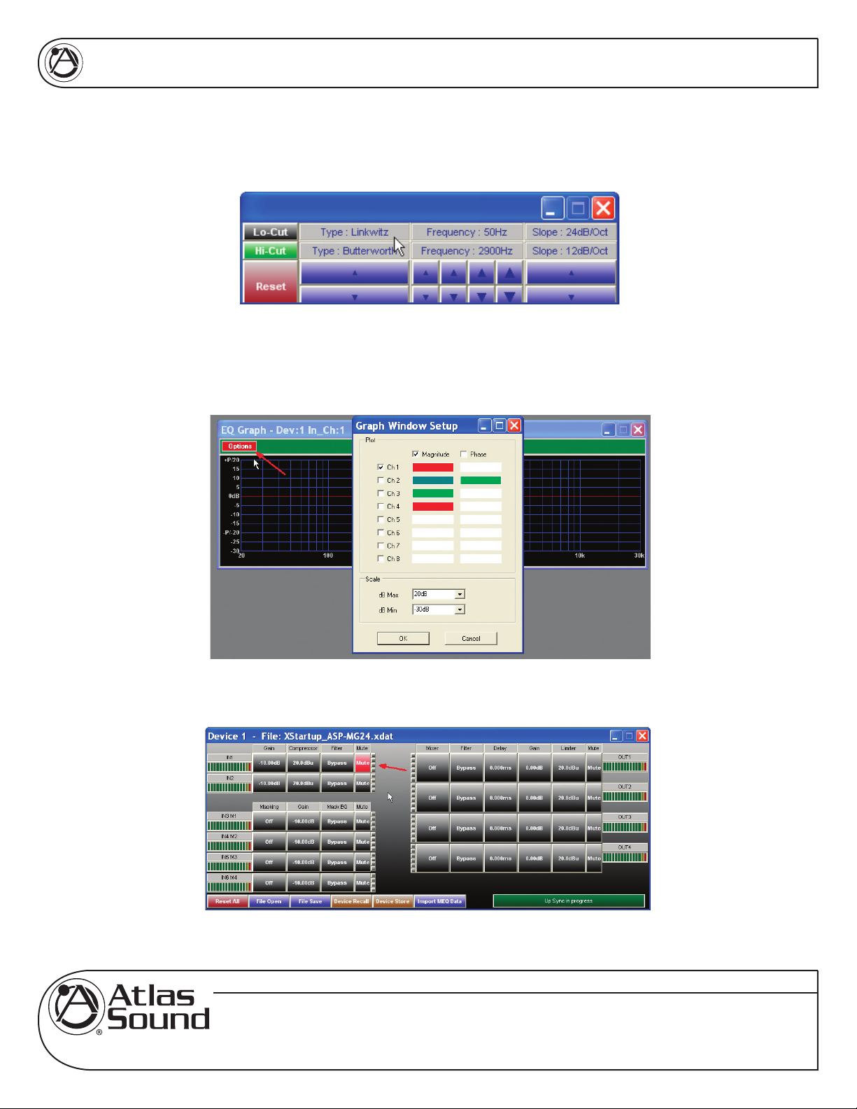
6.7 Crossover Window – The Crossover Window allows the adjustment of Filter type, Frequency, and slope.
The Reset button will set all filters back to factory settings. This Reset button only effects this screen settings.
6.8 Graph Sub Screen Window – Advance Viewing Feature - In the top right corner of the window there is
option button. This window allows you to view multiple channels of filters. Re set the viewing scale. The Reset
button will set all filters back to factory settings. This Reset button only effects this screen settings
OWNER'S MANUAL
6.9 Mute – This button when depressed turns Red and mutes the signal at the input of the channel.
Specifications are subject to change without notice
www.AtlasSound.com
© 2007 ATLAS SOUND LP Printed in U.S.A. ATS002766 RevA 4/07 11
1601 JACK MCKAY BOULEVARD ENNIS, TEXAS 75119 U.S.A. • TELEPHONE: (800) 876-3333 • FAX: (800) 765-3435
Page 12

ASP-MG24
OWNER'S MANUAL
7.0 MASKING GENERATOR INPUTS
7.1 Meter – There are four bar graph meters that illustrates the level of the output signal of the generator, it is
POST the channels gain control and PRE input filters.
7.2 Masking – When the Masking window a small window will open. This window also to the selection of the
filter either White or Pink noise.
7.3 Ramp Time - The Power Ramp button allows you set the desired turn on signal ramp time during power
up. The Time buttons allows you to adjust the amount of preset time you need. The amount of steps is a
formula of gain divided by time. The ramp interval voltage change will occur every 6 seconds. The amount
of dB steps will vary depending on the total ramp time you select and the amount of gain from change from
-40dB. Example: If you choose 2 minute of ramp time and the channels gain is set for -10dB, use the following
is the formula to calculate dB rate of change (Gain = -40dB minus -10dB = -30dB) and (Time = 120 seconds / 6
seconds = 20 steps) Gain Steps = 30dB / 20 steps = 1.5 dB change per second.
7.4 Ramp Bypass - If the Power UP Ramp button is Green the ramp feature is engaged, if grey the feature is
bypassed.
Specifications are subject to change without notice
www.AtlasSound.com
© 2007 ATLAS SOUND LP Printed in U.S.A. ATS002766 RevA 4/07 12
1601 JACK MCKAY BOULEVARD ENNIS, TEXAS 75119 U.S.A. • TELEPHONE: (800) 876-3333 • FAX: (800) 765-3435
Page 13

ASP-MG24
7.5 Gain - For you convenience both Mic / Line Inputs and the four masking generators levels are shown.
Controlling the gain can be accomplished by dragging the fader or by using the up down buttons or by typing in
number viewing text box. Channel Mute can be accomplished by clicking on the Mute tab and will illumination
Red indicating the channel is in Mute.
7.6 Masking EQ - When clicking on the filter screen, 3 sub viewing screens appear. Note: All three screens
can be moved for personal viewing preferences.
OWNER'S MANUAL
7.7 Graphic Screen – This screen will view all the all filter characteristics that are set. There 31 filter select
points on the screen. By dragging your curser over the number and left clicking the mouse and holding you can
drag the filter to the amount of boost or cut for a specified 1/3 octave frequency.
Specifications are subject to change without notice
www.AtlasSound.com
© 2007 ATLAS SOUND LP Printed in U.S.A. ATS002766 RevA 4/07 13
1601 JACK MCKAY BOULEVARD ENNIS, TEXAS 75119 U.S.A. • TELEPHONE: (800) 876-3333 • FAX: (800) 765-3435
Page 14

ASP-MG24
7.8 1/3rd Octave Graphic Screen – This screen corresponds with the Graph screen. There are 20 filters that
appear in this window. That is because the masking operating range is from 100Hz to 8KHz..Adjustments to
the filters can be made dragging the filter number on the screen or by typing the number into the window or by
using the UP / Down arrows. The Reset button will set all filters back to factory settings. This Reset button only
effects this screen settings.
OWNER'S MANUAL
7.9 Crossover Window – The Crossover Window allows the adjustment of Filter type, Frequency, and slope.
The Reset button will set all filters back to factory settings. This Reset button only effects this screen settings
Specifications are subject to change without notice
www.AtlasSound.com
© 2007 ATLAS SOUND LP Printed in U.S.A. ATS002766 RevA 4/07 14
1601 JACK MCKAY BOULEVARD ENNIS, TEXAS 75119 U.S.A. • TELEPHONE: (800) 876-3333 • FAX: (800) 765-3435
Page 15

ASP-MG24
7.10 Mute - This button when depressed turns Red and mutes the signal at the input of the channel.
OWNER'S MANUAL
8.0 OUTPUT WINDOWS
8.1 Mixer – This button allows you to route or mix any of the inputs to this output. When clicking on this
button a window will appear that shows all six inputs. Each input channels gain operates from OFF to 0dB.
Controlling the mixed gain can be accomplished by dragging the fader or by using the up down buttons or by
typing in number viewing text box. Note: The signal feeding into the mixer will not be effect by other output
channel mixes. When you have completed you routing or mix you can view the route by channel indicator
lines or by the number of channels indicated in the mixer viewing window.
Specifications are subject to change without notice
www.AtlasSound.com
© 2007 ATLAS SOUND LP Printed in U.S.A. ATS002766 RevA 4/07 15
1601 JACK MCKAY BOULEVARD ENNIS, TEXAS 75119 U.S.A. • TELEPHONE: (800) 876-3333 • FAX: (800) 765-3435
Page 16

ASP-MG24
8.2 Filter - When clicking on the filter screen 3 sub viewing screens appear. Note: All three screens can be
moved for personal viewing preferences.
OWNER'S MANUAL
8.3 Graphic Screen – This screen will view all the all filter characteristics that are set.
8.4 Filter Window – Each input has 8 adjustable filter selections. Choices are Parametric, Hi-shelf and Lo-
shelf. Adjustments can be made via the up / down arrows, text window and by dragging the curser on the
Graphics Screen. After any adjustment made they should appear on the Graphic Screen.
Specifications are subject to change without notice
www.AtlasSound.com
© 2007 ATLAS SOUND LP Printed in U.S.A. ATS002766 RevA 4/07 16
1601 JACK MCKAY BOULEVARD ENNIS, TEXAS 75119 U.S.A. • TELEPHONE: (800) 876-3333 • FAX: (800) 765-3435
Page 17

ASP-MG24
8.5 Crossover Window – The Crossover Window allows the adjustment of Filter type, Frequency, and slope.
The Reset button will set all filters back to factory settings. This Reset button only effects this screen settings.
8.6 Delay Window – The delay window allows you adjust the channels delay from 0ms to 200ms per output.
Controlling the mixed gain can be accomplished by using the up down buttons or by typing in number viewing
text box.
OWNER'S MANUAL
8.7 Gain - The four output gain levels are shown when clicking on this window. Controlling the gain can be
accomplished by dragging the fader or by using the up down buttons or by typing in number viewing text box.
Channel Mute can be accomplished by clicking on the Mute tab and will illumination Red indicating the channel
is in Mute. Input Polarity can be set by clicking on the tab.
Specifications are subject to change without notice
www.AtlasSound.com
© 2007 ATLAS SOUND LP Printed in U.S.A. ATS002766 RevA 4/07 17
1601 JACK MCKAY BOULEVARD ENNIS, TEXAS 75119 U.S.A. • TELEPHONE: (800) 876-3333 • FAX: (800) 765-3435
Page 18

ASP-MG24
8.8 Limiter – All four outputs have fully adjustable limiters. When clicking on the compressor tab, two sub
viewing screens will appear. Note: All control boxes can be dragged for desired positioning of the screen.
Screen 1 is an indicator screen showing the compressor / limiter operation. The second is the settings screen.
In that screen you have control over Threshold, Attack, Release and Ratio. Adjustment can be made using the
Up / Down arrows or by typing into the data viewing text box.
OWNER'S MANUAL
• THRESHOLD - Limit Threshold. Ranges from -20 to +20dBu in 0.5dB steps.
• ATTACK - Attack time. Ranges from 0.3 to 1ms in 0.1ms steps, and ranges from 1 to
100ms in 1ms steps.
• RELEASE - Release time. Can be set at 2X, 4X, 8X, 16X or 32X the attack time.
• RATIO – The Ratio control allows adjustment to the amount of Input vs. Output level with
signals exceeding the set threshold limit.
Specifications are subject to change without notice
www.AtlasSound.com
© 2007 ATLAS SOUND LP Printed in U.S.A. ATS002766 RevA 4/07 18
1601 JACK MCKAY BOULEVARD ENNIS, TEXAS 75119 U.S.A. • TELEPHONE: (800) 876-3333 • FAX: (800) 765-3435
Page 19

ASP-MG24
8.9 Mute - Channel Mute can be accomplished by clicking on the Mute tab and will illumination Red indicating
the channel is in Mute.
8.10 Output Meter - The bar graph meter illustrates the level of the output signal POST the channels gain
control and filters but is PRE Limiter settings.
OWNER'S MANUAL
9.0 FILE IMPORT AND EXPORT
Specifications are subject to change without notice
www.AtlasSound.com
© 2007 ATLAS SOUND LP Printed in U.S.A. ATS002766 RevA 4/07 19
1601 JACK MCKAY BOULEVARD ENNIS, TEXAS 75119 U.S.A. • TELEPHONE: (800) 876-3333 • FAX: (800) 765-3435
Page 20

ASP-MG24
9.1 Master Reset All – This button is the master rest button and will override all settings. Note: It will ask you if
you are sure.
9.2 File Open – Program files can be recalled from your PC or Laptop. It operates like any other window files
storing device. For your convenience you can preprogram a file in demo mode, save the file and loaded later
into the device.
OWNER'S MANUAL
9.3 File Save - Program files can be saved to your PC or Laptop. It operates like any other window files storing
device. For your convenience you can preprogram a file in demo mode, save the file and loaded later into the
device.
Specifications are subject to change without notice
www.AtlasSound.com
© 2007 ATLAS SOUND LP Printed in U.S.A. ATS002766 RevA 4/07 20
1601 JACK MCKAY BOULEVARD ENNIS, TEXAS 75119 U.S.A. • TELEPHONE: (800) 876-3333 • FAX: (800) 765-3435
Page 21

ASP-MG24
9.4 Device Recall - The ASP-MG24 has a built in non-volatile memory that can store up to 30 different
program setups. A program can be recalled from the device. When doing so, only one program can be open on
the desktop GUI. Once recalled, the program name and number will be at the top of the main screen.
9.5 Device Store - The ASP-MG24 has a built in non-volatile memory that can store up to 30 different program
setups. A program can be stored using this menu. The old program with the same program number will be
replaced. Once the program is stored in the flash memory, it can be recalled at a later time, even after power
down.
OWNER'S MANUAL
Specifications are subject to change without notice
www.AtlasSound.com
© 2007 ATLAS SOUND LP Printed in U.S.A. ATS002766 RevA 4/07 21
1601 JACK MCKAY BOULEVARD ENNIS, TEXAS 75119 U.S.A. • TELEPHONE: (800) 876-3333 • FAX: (800) 765-3435
Page 22

ASP-MG24
9.6 Import MEQ Data – This window allow you to directly import files from the Atlas Sound room measurement
software called MEQ. This is an advanced feature, contact support for more details.
9.7 Sync Process – This window indicates the status of the connection between the GUI software and the
devices. This window corresponds with Setup/ Port Connection window at the top of the page.
OWNER'S MANUAL
Specifications are subject to change without notice
www.AtlasSound.com
© 2007 ATLAS SOUND LP Printed in U.S.A. ATS002766 RevA 4/07 22
1601 JACK MCKAY BOULEVARD ENNIS, TEXAS 75119 U.S.A. • TELEPHONE: (800) 876-3333 • FAX: (800) 765-3435
Page 23

ASP-MG24
10.0 SPECIFICATIONS
• Type; DSP Controller 2x4 Speaker Processor / Masking Generator
• Input Impedance: Line 10k Ohms, Mic
• Output Impedance: 50 Ohms
• Maximum Input & Output Level: +20dBu
• Frequency Response: +/- 0.1dB (20 to 20kHz)
• Dynamic Range: 115dB (unweighted)
• CMMR: > 60dB (50 to 10kHz)
• Crosstalk: < -100dB
• Distortion: 0.02% (1kHz @+4dBu)
• Processor: 32-bit (40-bit extended)
• Sampling Rate: 96kHz
• Analog Converters: High Performance 24-bit
• Propagation Delay: 3ms
Front Panel
• Level Meters: In/Out 5 segment LED
• RS-232: Female DB-9
• Power LED
• Data Status LED
• USB Interface
OWNER'S MANUAL
Rear Panel
• 2 selectable Mic / Line Inputs, 3-pin balanced Phoenix
• 2 Mic / line Switches
• 4 Outputs, 3-pin balanced Phoenix
• DC Power Receptacle
General
• Power: 115V 20W UL Rated External DC Power Supply
• Dimensions: 19”x1.75”x8” (483x44x203 mm)
• Weight: 13.2 lbs / 6 kg
Specifications are subject to change without notice
www.AtlasSound.com
© 2007 ATLAS SOUND LP Printed in U.S.A. ATS002766 RevA 4/07 23
1601 JACK MCKAY BOULEVARD ENNIS, TEXAS 75119 U.S.A. • TELEPHONE: (800) 876-3333 • FAX: (800) 765-3435
Page 24

ASP-MG24
OWNER'S MANUAL
Audio Control Parameters
• Gain: -40dB to +15dB in 0.25dB steps
• Polarity: +/-
• Delay: Up to 200ms per I/O
• Parametric Filters (8 per I/O)
• Hi-shelf, Lo-shelf Filters
• Filter Bandwidth: 0.02 to 2.50 octaves (Q=0.5 to 72)
• Masking Inputs
o 4 Independent generators
o White or Pink Noise
o 31 Band EQ per output
o Parametric Filters, Crossover, Gain per output
o Turn on Auto ramp 0:00 – 10:00 min
• Crossover Filters (2 per Output)
o Filter Types: Butterworth, Bessel, Linkwitz Riley
o Slopes: 6 to 48dB/oct
• Compressor / Limiters
o Threshold: -20 to +20dBu
o Ratio: 1:40
o Attack: 0.3 to 100ms
o Release: 2 to 32X the attack time
System Parameters
• No. of Programs: 30
• Program Names: 12 character length
• Delay Units: ms, ft, m
• Security Locks: System
PASSWORD – The password of the ASP-MG24 is 4 characters in length. The user can change it via the PC
application software. The factory default of a new unit does not require a password
Option Graph Sub Screen Window – In the top right corner of the window there is Option button. This window
allows you to view multiple channels of filters. Graph viewing scale. The Reset button will set all filters back to
factory settings. This Reset button only effects this screen settings
Graph Sub Screen Window – In the top right corner of the window there is option button. This window allows
you to view multiple channels of filters. Graph viewing scale. The Reset button will set all filters back to factory
settings. This Reset button only effects this screen settings
Specifications are subject to change without notice
www.AtlasSound.com
© 2007 ATLAS SOUND LP Printed in U.S.A. ATS002766 RevA 4/07 24
1601 JACK MCKAY BOULEVARD ENNIS, TEXAS 75119 U.S.A. • TELEPHONE: (800) 876-3333 • FAX: (800) 765-3435
Page 25

ASP-MG24
NOTES:
OWNER'S MANUAL
Specifications are subject to change without notice
www.AtlasSound.com
© 2007 ATLAS SOUND LP Printed in U.S.A. ATS002766 RevA 4/07 25
1601 JACK MCKAY BOULEVARD ENNIS, TEXAS 75119 U.S.A. • TELEPHONE: (800) 876-3333 • FAX: (800) 765-3435
Page 26

ASP-MG24
NOTES:
OWNER'S MANUAL
Specifications are subject to change without notice
www.AtlasSound.com
© 2007 ATLAS SOUND LP Printed in U.S.A. ATS002766 RevA 4/07 26
1601 JACK MCKAY BOULEVARD ENNIS, TEXAS 75119 U.S.A. • TELEPHONE: (800) 876-3333 • FAX: (800) 765-3435
Page 27

ASP-MG24
NOTES:
OWNER'S MANUAL
Specifications are subject to change without notice
www.AtlasSound.com
© 2007 ATLAS SOUND LP Printed in U.S.A. ATS002766 RevA 4/07 27
1601 JACK MCKAY BOULEVARD ENNIS, TEXAS 75119 U.S.A. • TELEPHONE: (800) 876-3333 • FAX: (800) 765-3435
Page 28

ASP-MG24
OWNER'S MANUAL
Limited Warranty
All products manufactured by Atlas Sound are warranted to the original dealer/installer, industrial or
commercial purchaser to be free from defects in material and workmanship and to be in compliance with
our published specifications, if any. This warranty shall extend from the date of purchase for a period of
one year on all Atlas Sound products, including SOUNDOLIER brand, and ATLAS SOUND brand products
except as follows: one year on electronics and control systems; one year on replacement parts; and one
year on Musician Series stands and related accessories. Additionally, fuses and lamps carry no warranty.
Atlas Sound will solely at its discretion, replace at no charge or repair free of charge defective parts
or products when the product has been applied and used in accordance with our published operation
and installation instructions. We will not be responsible for defects caused by improper storage, misuse
(including failure to provide reasonable and necessary maintenance), accident, abnormal atmospheres,
water immersion, lightning discharge, or malfunctions when products have been modified or operated in
excess of rated power, altered, serviced or installed in other than a workman like manner. The original
sales invoice should be retained as evidence of purchase under the terms of this warranty. All warranty
returns must comply with our returns policy set forth below. When products returned to Atlas Sound do
not qualify for repair or replacement under our warranty, repairs may be performed at prevailing costs for
material and labor unless there is included with the returned product(s) a written request for an estimate of
repair costs before any nonwarranty work is performed. In the event of replacement or upon completion of
repairs, return shipment will be made with the transportation charges collect.
EXCEPT TO THE EXTENT THAT APPLICABLE LAW PREVENTS THE LIMITATION OF
CONSEQUENTIAL DAMAGES FOR PERSONAL INJURY, ATLAS SOUND SHALL NOT BE LIABLE IN
TORT OR CONTRACT FOR ANY DIRECT, CONSEQUENTIAL OR INCIDENTAL LOSS OR DAMAGE
ARISING OUT OF THE INSTALLATION, USE OR INABILITY TO USE THE PRODUCTS. THE ABOVE
WARRANTY IS IN LIEU OF ALL OTHER WARRANTIES INCLUDING BUT NOT LIMITED TO
WARRANTIES OF MERCHANTABILITY AND FITNESS FOR A PARTICULAR PURPOSE.
Atlas Sound does not assume, or does it authorize any other person to assume or extend on its behalf,
any other warranty, obligation, or liability. This warranty gives you specific legal rights and you may have
other rights which vary from state to state.
SERVICE
Should your PA601 amplifier require service, please contact the Atlas Sound warranty department at 1-
877-689-8055, ext. 277 to obtain an RA number.
Atlas Sound Tech Support can be reached at 1-800-876-3333.
Visit our website at www.AtlasSound.com to see other Atlas products.
Specifications are subject to change without notice
www.AtlasSound.com
© 2007 ATLAS SOUND LP Printed in U.S.A. ATS002766 RevA 4/07 28
1601 JACK MCKAY BOULEVARD ENNIS, TEXAS 75119 U.S.A. • TELEPHONE: (800) 876-3333 • FAX: (800) 765-3435
 Loading...