

Page 1
AH SERIES LOUDSPEAKERS
8", 12", AND 15"
INSTALLATION INSTRUCTIONS
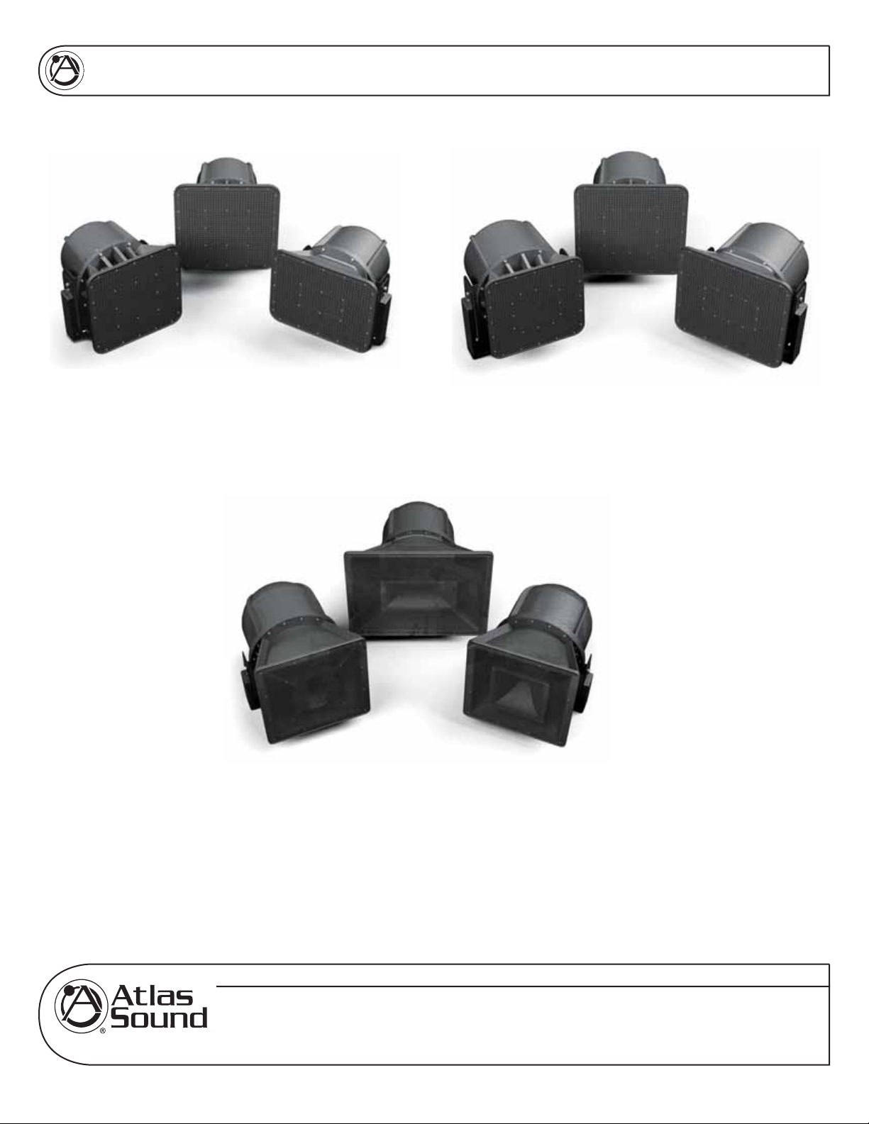
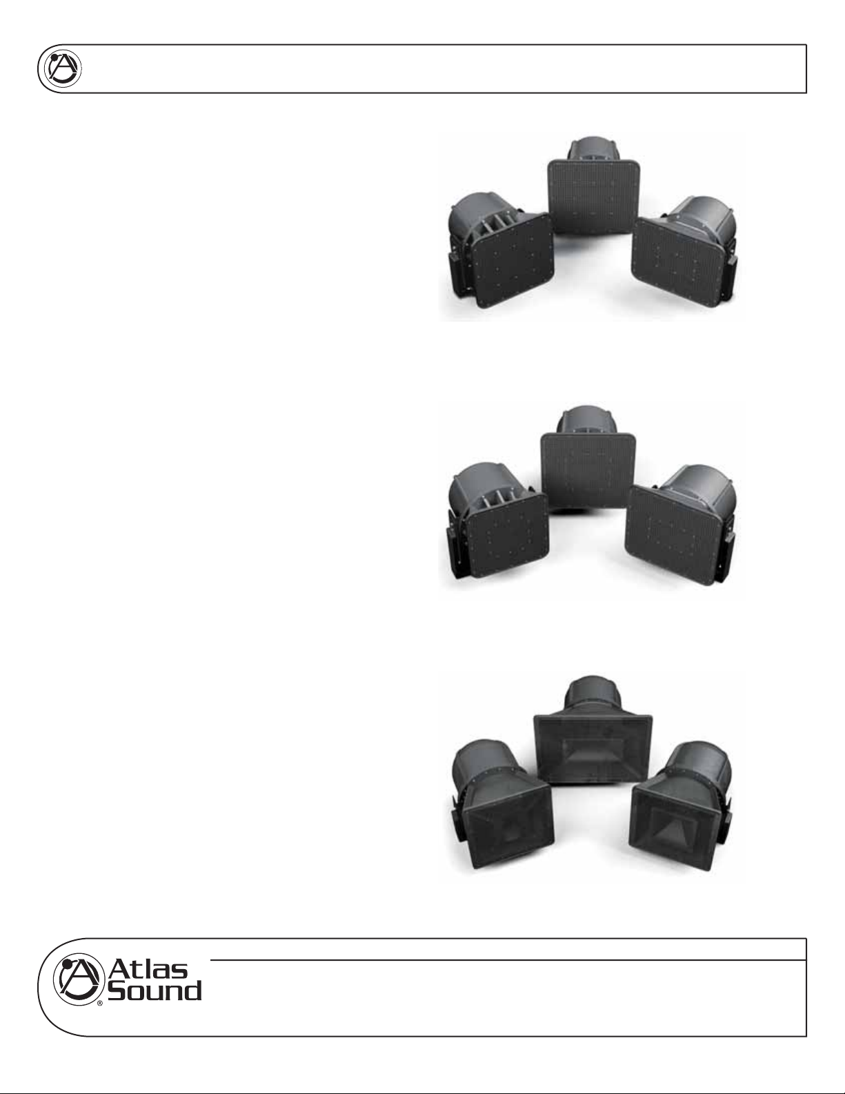
8" - AH99-8ST, AH94-8ST, and AH66-8ST
15" - AH5040S, AH9040S, and AH6565S
12" - AH99-12ST, AH94-12ST, and AH66-12ST
AH Series Stadium Loudspeakers 8", 12", 15"
HIGH-PERFORMANCE, CONSTANT DIRECTIVITY, 8", 12", and 15",
TWO-WAY, INDOOR/OUTDOOR LOUDSPEAKER SYSTEMS
Specifications are subject to change without notice
AtlasSound.com
1601 JACK MCKAY BOULEVARD ENNIS, TEXAS 75119 U.S.A. • TELEPHONE: (800) 876-3333 • FAX: (800) 765-3435
©2006 ATLAS SOUND LP Printed in U.S.A. 000606 ATS002386 RevA 6/06 PP
1
Page 2

AH SERIES LOUDSPEAKERS
8", 12", AND 15"
INSTALLATION INSTRUCTIONS
TABLE OF CONTENTS
Safety Instructions…………………………………………………………………………………………………..3
Suspension and Mounting………………………………………………………………………………………….3
Introduction, Features, Applications……………………………………………………………………………….4
Installation Via Mounting Bracket………………………………………………………………………………….5
Suspended Installation Via Eyebolts………………………………………………………………………………8
Speaker Cable Recommendations and Connection…………………………………………………………….9
Amplifi er Considerations…………………………………………………………………………………………..10
Specifi cations……………………………………………………………………………………………………….1 1
Troubleshooting…………………………………………………………………………………………………….11
Warranty…………………………………………………………………………………………………………….12
Specifications are subject to change without notice
AtlasSound.com
1601 JACK MCKAY BOULEVARD ENNIS, TEXAS 75119 U.S.A. • TELEPHONE: (800) 876-3333 • FAX: (800) 765-3435
©2006 ATLAS SOUND LP Printed in U.S.A. 000606 ATS002386 RevA 6/06 PP
2
Page 3

AH SERIES LOUDSPEAKERS
8", 12", AND 15"
INSTALLATION INSTRUCTIONS
SAFETY INSTRUCTIONS
Please Read Carefully Before Installing or Operating
• Read all instructions carefully
• Heed all warnings
• Assure that the speaker is securely mounted
Hearing Damage
CAUTION: All professional loudspeaker systems are capable of generating very high sound pressure
levels. Use care with placement and operation to avoid exposure to excessive levels that can cause
permanent hearing damage.
SUSPENSION & MOUNTING
Suspension or "fl ying" speaker systems requires training and expertise. Improper rigging of a fl ying
speaker may result in injury, death, equipment damage, and legal liability. Installation must be carried
out by fully qualifi ed installers, in accordance with all required safety codes and standards at the place of
installation.
A 5:1 design factor is a generally accepted minimum standard. However, legal requirements for overhead
suspension vary by municipality, please consult your local safety standards offi ce before installing any
product. We also recommend that you thoroughly check any laws and bylaws prior to installation.
Loudspeakers fl own in theaters, nightclubs, conference centers, or other places of work and
entertainment must be provided with an independent, correctly rated and securely attached secondary
safety — in addition to the principle suspension point(s). This secondary safety must prevent the
loudspeaker from dropping more than (6") should the principle suspension device fail. If you lack the
skills, training, and proper ancillary equipment to fl y a speaker system, do not attempt to do so.
For additional information regarding the suspension of loudspeakers or to purchase rigging materials,
please contact our friends at
ATM Group, Inc.,1635 E. Burnett St. Signal Hills, CA 90755.
www.atmfl yware.com
Telephone (562) 424-1100 and Fax (562) 424-3520
• Always assure power is off to amplifi ers before making any connections
• Assure that all electrical equipment is properly grounded
• Keep instructions for future reference
• Should any questions arise after reading this document, please call Atlas Sound Tech Support at
800-876-3333
Specifications are subject to change without notice
AtlasSound.com
1601 JACK MCKAY BOULEVARD ENNIS, TEXAS 75119 U.S.A. • TELEPHONE: (800) 876-3333 • FAX: (800) 765-3435
©2006 ATLAS SOUND LP Printed in U.S.A. 000606 ATS002386 RevA 6/06 PP
3
Page 4
AH SERIES LOUDSPEAKERS
8", 12", AND 15"
AH SERIES LOUDSPEAKER SYSTEMS
Thank you for your purchase of an Atlas Sound AH
Series loudspeaker system. We have designed this
product to be a reliable and versatile solution to your
needs for years to come.
All models in the AH Series feature high output,
outstanding pattern control and amazing low
frequency response for indoor and outdoor
applications including football stadiums, sports
arenas, baseball fi elds, and large auditoriums.
A variety of 8", 12", and 15" models are offered to
ensure that most any seating area or speaker to
loudspeaker distance may be accommodated.
All units feature effi cient low frequency woofers
and a coaxial mounted 1" exit compression drivers
to provide excellent frequency response. A highly
effi cient internal passive crossover network insures
proper transition between the (2) drivers.
INSTALLATION INSTRUCTIONS
8" - AH99-8ST, AH94-8ST, and AH66-8ST
FEATURES
• Impressive effi ciency ratings exceeding 100dB
1Watt/1Meter (model dependent) makes the
AH series a perfect choice for high energy music
playback at sporting events as well as extended
range speech reinforcement.
• Weather & rodent resistant. Multiple mesh screens
over the front of the main horn protect the speaker
from weather and/or rodent damage.
• Easy installation. Heavy duty stainless steel
mounting bracket is included.
APPLICATIONS
The AH Series is ideal for stadiums, outdoor fi elds,
theaters, auditoriums, and convention center spaces
and may be used for paging, announcements,
background/foreground music, and/or internal
communications.
12" - AH99-12ST, AH94-12ST, and AH66-12ST
15" - AH5040S, AH9040S, and AH6565S
Specifications are subject to change without notice
AtlasSound.com
1601 JACK MCKAY BOULEVARD ENNIS, TEXAS 75119 U.S.A. • TELEPHONE: (800) 876-3333 • FAX: (800) 765-3435
©2006 ATLAS SOUND LP Printed in U.S.A. 000606 ATS002386 RevA 6/06 PP
4
Page 5

AH SERIES LOUDSPEAKERS
8", 12", AND 15"
INSTALLATION INSTRUCTIONS
INSTALLATION VIA MOUNTING BRACKET (INCLUDED)
General considerations and hardware recommendations
CAUTION: AH series models weigh as much as 81 pounds (36.7kg) – model AH5040CD. A fall from
almost any height could result in serious injury or death. Assure that the speaker is fi rmly mounted to an
object that can handle the weight of the AH speaker. Remember that wind will add considerable torque
to the point of attachment. The mounting surface the AH speaker is being attached to should be able to
handle fi ve or more times the weight of the AH speaker (7x recommended for locations subject to high
wind forces).
Whenever the loudspeaker is mounted to a surface using the bracket, the installer must ensure that the
surface is capable of safely and securely supporting the load. The hardware employed must be safely and
securely attached both to the loudspeaker and the surface in question, using only the mounting holes. A
general rule for soft surface installations (wood beams) is to multiply the corresponding working load limit
by 75%: the result will be an approximate working load strength.
Use thread locking compound for all installations.
CAUTION: Mount the speaker such that the shear force is at a right angle to the mounting bolts, and
close to the connection, as shown:
TENSION FORCE
Lock Washer
SHEAR FORCE
Flat Washer
When mounting the AH speaker to a solid surface use the proper bolts, washers, and lock washers
(Grade 5 minimum). Do not substitute mismatched bolts and washers.
The AH speaker may be mounted to a pole or scoreboard. For such mounting, contact the light pole or
scoreboard manufacturer for proper instructions.
If mounting to another surface, such as a beam, see the diagram on page 7 for mounting hole locations.
When in doubt contact a qualifi ed structural/mechanical engineer for approval of the mounting
materials and methods.
Specifications are subject to change without notice
AtlasSound.com
1601 JACK MCKAY BOULEVARD ENNIS, TEXAS 75119 U.S.A. • TELEPHONE: (800) 876-3333 • FAX: (800) 765-3435
©2006 ATLAS SOUND LP Printed in U.S.A. 000606 ATS002386 RevA 6/06 PP
5
Page 6

AH SERIES LOUDSPEAKERS
8", 12", AND 15"
Assure that the AH speaker can be mounted in a manner that the sound pattern will be directed in the
desired direction without any physical interference. Note that the AH speaker mounting bracket allows the
speaker to be tilted in excess of 50 degrees in either direction. See illustration below.
INSTALLATION INSTRUCTIONS
50˚
50˚
Weep-holes (for drainage) (AH5040S, AH9040S, and AH6565S 15" models only) are located on the same
side as the input connectors. If the speaker is tilted above parallel to the ground, the speaker should be
installed with the weep holes down for water drainage.
Specifications are subject to change without notice
AtlasSound.com
1601 JACK MCKAY BOULEVARD ENNIS, TEXAS 75119 U.S.A. • TELEPHONE: (800) 876-3333 • FAX: (800) 765-3435
©2006 ATLAS SOUND LP Printed in U.S.A. 000606 ATS002386 RevA 6/06 PP
6
Page 7

AH SERIES LOUDSPEAKERS
8", 12", AND 15"
INSTALLATION INSTRUCTIONS
Mounting
CAUTION: Mounting the AH loudspeaker requires two people, unless it is possible to safely clamp the
speaker in position for alignment before mounting.
The bracket may be removed from the speaker for installation convenience. When re-attaching speaker to
bracket be sure to tightly secure speaker mounting bolts. Thread locking compound should also be used
in this operation.
1. Choose the bracket mounting holes best suited for the surface you are mounting to. For best
stability the 5⁄8" (16mm) diameter outer keyhole slots are recommended.
2. When using these mounting holes 1⁄2" (grade 5 hardware minimum) hardware should be used
with proper fl at and lock washers. Remember to use thread- locking compound on all parts.
3. Use the dimensions noted on the illustration to mark the points where the starting hole should be
drilled.
4. Choose appropriately sized bit and drill holes.
5. Attach speaker bracket, using bolt, fl at washer, and lock washer as shown and re-attach
loudspeaker to bracket.
6. Secondary (safety) suspension point: Use a load rated cable or steel chain (capable of holding
the speaker should it come loose from the primary mounting point). This cable or chain assembly
should be attached to at least (2) of the drop forge eyebolts provided on the AH speaker and
secured to the mounting surface via approved, load rated hardware.
0“0.
5
1.21
3“
5“
7.2
5“7.
8
BOTTOM VIEW
Specifications are subject to change without notice
AtlasSound.com
©2006 ATLAS SOUND LP Printed in U.S.A. 000606 ATS002386 RevA 6/06 PP
1601 JACK MCKAY BOULEVARD ENNIS, TEXAS 75119 U.S.A. • TELEPHONE: (800) 876-3333 • FAX: (800) 765-3435
7
Page 8

AH SERIES LOUDSPEAKERS
8", 12", AND 15"
INSTALLATION INSTRUCTIONS
SUSPENDED INSTALLATION VIA EYEBOLTS (INCLUDED)
Using 1⁄4" Diameter Wire Rope
Note: Use of 1⁄4" load rated wire rope is suggested to provide a static working load limit of 1400lbs (635kg)
and moving load limit of 875lbs (397kg) per point. 1⁄8" cable is not recommended as load limits are reduced
to 400lbs (181kg) static, and 250lbs (113kg) moving.
Considerations for overhead suspension using AH Series eyebolts and wire rope:
1. Always apply the load to the eye in the plane of the eye.
2. Always use shoulder eyebolts for angular lifts.
3. Always tighten eyebolts securely against the load.
4. Apply fi rst load to test the assembly. This load should be of equal or greater weight than the loads
expected in use.
5. Use wire rope compression fi ttings & thimbles whenever possible and prepare terminations only
as instructed by the manufacturer.
6. If wire rope clips are used, check and retighten to the manufacturer's recommended torque.
90˚
Eyebolt Working Load Limits
1
⁄4" Shank (Provided with AH Series)
90˚ angle: 650lbs (295kg)
60˚ angle: 420lbs (191kg)
45˚ angle: 195lbs (88kg)
60˚
45˚
LESS THAN
45 DEGREE
ANGLE
0 ANGLE
Less than 45˚ angle: 160lbs (73kg)
Specifications are subject to change without notice
AtlasSound.com
1601 JACK MCKAY BOULEVARD ENNIS, TEXAS 75119 U.S.A. • TELEPHONE: (800) 876-3333 • FAX: (800) 765-3435
©2006 ATLAS SOUND LP Printed in U.S.A. 000606 ATS002386 RevA 6/06 PP
8
Page 9

AH SERIES LOUDSPEAKERS
8", 12", AND 15"
INSTALLATION INSTRUCTIONS
SPEAKER CABLE RECOMMENDATIONS AND CONNECTION INSTRUCTIONS
Wire Gauges (8 Ohm operation)
For very short distance speaker cable runs (less than 25') #16-gauge, stranded, twisted pair speaker
cable may be used. For speaker cable runs between 25' and 75', #14-gauge, stranded, twisted pair
speaker cable is recommended. For speaker cable runs greater than 75', #12-gauge, stranded, twisted
pair speaker cable is necessary. For runs exceeding 150', please contact tech support for proper wire
gauge or other installation solution using the Atlas Sound AF140 autoformer.
15" models AH5040S, AH9040S, and AH6565S input connections are provided on a convenient recessed
terminal block located on the bottom of the loudspeaker. This terminal block includes a clear weather
resistant cover which should be re-installed after terminating the speaker cabling to prevent corrosion in
outdoor applications.
8" & 12" models include a built-in, high effi ciency 60 Watt 70.7V transformer. 7.5, 15, 30, and 60 Watt
taps are available on a convenient recessed terminal block located on the bottom of the loudspeaker.
A removable jumper and additional pole on the terminal block is included for 8 Ohm direct coupled
operation. This terminal block includes a clear weather resistant cover which should be re-installed after
terminating the speaker cabling to prevent corrosion in outdoor applications.
Allow an adequate service loop for this connection to allow tilt of the loudspeaker. If the speaker is tilted
above parallel to the ground, the speaker should be installed angled slightly down for water drainage — in
other words, the product should not be installed tilted upwards!
ACCESS HOLES FOR SPEAK-ON
CONNECTORS
HOLE FOR STRAIN
RELIEF
Specifications are subject to change without notice
AtlasSound.com
1601 JACK MCKAY BOULEVARD ENNIS, TEXAS 75119 U.S.A. • TELEPHONE: (800) 876-3333 • FAX: (800) 765-3435
©2006 ATLAS SOUND LP Printed in U.S.A. 000606 ATS002386 RevA 6/06 PP
9
Page 10

AH SERIES LOUDSPEAKERS
8", 12", AND 15"
INSTALLATION INSTRUCTIONS
AMPLIFIER CONSIDERATIONS
Consult your amplifi er owner’s manual to confi rm power output at the rated impedance.
15" models: AH5040S, AH9040S, and AH6565S and other models used in 8 Ohm confi guration
Each model exhibits an 8 Ohm (nominal) impedance.
(x2) AH models paralleled will present a 4 Ohm load to the amplifi er.
(x3) AH models paralleled will present a 2.66 Ohm load to the amplifi er.
(x4) AH models paralleled will present a 2 Ohm load to the amplifi er.
ATLAS SOUND speaker system specifi cations list RMS power handling.
As a reference peak power = RMS x 1.414.
These ratings should be considered in selecting the best amplifi er to power the speaker system.
For general use, amplifi er output should match or exceed the RMS rated power of the speaker system:
(250 Watts for the 15" AH models, 200 Watts for the 12" models and 100 Watts for 8" models).
For increased headroom and dynamic reproduction, the amplifi er’s output should match or exceed the
peak power rating of the speaker system (354 Watts for the 15" AH models, 283 Watts for 12" models
and 141 Watts for 8" models).
In situations where experienced professionals are operating the speaker system with proper limiting
and frequency control devices inserted into the signal path and adjusted properly, amplifi er output may
meet, but should not exceed 2x the RMS power rating of the speaker system (500 Watts for the 15" AH
models, 400 Watts for 12" AH models, and 200 Watts for 8" AH models).
Utilizing the Atlas Sound model CP700 power amplifi er will allow you to easily match required power
ratings for most any installation. Visit www.AtlasSound.com for more details on this product.
Specifications are subject to change without notice
AtlasSound.com
1601 JACK MCKAY BOULEVARD ENNIS, TEXAS 75119 U.S.A. • TELEPHONE: (800) 876-3333 • FAX: (800) 765-3435
©2006 ATLAS SOUND LP Printed in U.S.A. 000606 ATS002386 RevA 6/06 PP
10
Page 11

AH SERIES LOUDSPEAKERS
8", 12", AND 15"
SPECIFICATIONS
INSTALLATION INSTRUCTIONS
8" MODELS POWER RATING FREQUENCY
RES. ±5dB
AH99-8ST 100 Watts 90Hz to 10kHz 121dB 101dB 90˚ H
AH94-8ST 100 Watts 90Hz to 10kHz 121dB 101dB 90˚ H
AH66-8ST 100 Watts 90Hz to 10kHz 120dB 100dB 65˚ H
12" MODELS POWER RATING FREQUENCY
RES. ±5dB
AH99-12ST 200 Watts 80Hz to 10kHz 126dB 103dB 90˚ H
AH94-12ST 200 Watts 80Hz to 10kHz 126dB 103dB 90˚ H
AH66-12ST 200 Watts 80Hz to 10kHz 125dB 102dB 65˚ H
15" MODELS POWER RATING FREQUENCY
RES. ±5dB
AH5040S 250 Watts 75Hz to 14.5kHz 127dB 104dB 50˚ H
AH6565S 250 Watts 75Hz to 14.5kHz 126dB 102dB 65˚ H
AH9040S 250 Watts 75Hz to 14.5kHz 126.5dB 102.5dB 90˚ H
SOUND LEVEL DISPERSION IMPEDANCE XFMR TAPS DIMENSIONS WEIGHT
RP/1M 1W/1M
90˚ V
40˚ V
65˚ V
SOUND LEVEL DISPERSION IMPEDANCE XFMR TAPS DIMENSIONS WEIGHT
RP/1M 1W/1M
90˚ V
40˚ V
65˚ V
SOUND LEVEL DISPERSION IMPEDANCE DIMENSIONS WEIGHT
RP/1M 1W/1M
8Ω Nominal 3.8, 7.5, 15,
8Ω Nominal 3.8, 7.5, 15,
8Ω Nominal 3.8, 7.5, 15,
8Ω Nominal 3.8, 7.5, 15,
8Ω Nominal 3.8, 7.5, 15,
8Ω Nominal 3.8, 7.5, 15,
8Ω Nominal 20.5" (521mm) D
40˚ V
8Ω Nominal 20.5" (521mm) D
65˚ V
8Ω Nominal 22.5" (572mm) D
40˚ V
30, and 60
Watts
30, and 60
Watts
30, and 60
Watts
30, and 60
Watts
30, and 60
Watts
30, and 60
Watts
20.5" (521mm) W
32" (813mm) H
20.5" (521mm) W
32" (813mm) H
30" (762mm) W
31" (787mm) H
23.86" (606mm) D
21.41" (544mm) W
21.25" (540mm) H
21.83" (554mm) D
19.66" (499mm) W
18.41" (468mm) H
20.91" (531mm) D
17.91" (455mm) W
19.66" (499mm) H
25.65" (652mm) D
22.06" (560mm) W
21.25" (540mm) H
25.65" (652mm) D
22.06" (560mm) W
21.25" (540mm) H
23.86" (606mm) D
21.41" (544mm) W
21.25" (540mm) H
87 lbs
(39.5 kg)
87 lbs
(89.5 kg)
100 lbs
(45.4 kg)
65 lbs
(24.5 kg)
63 lbs
(28.6 kg)
61 lbs
(27.7 kg)
87 lbs
(39.5 kg)
85 lbs
(38.6 kg)
82 lbs
(37.2 kg)
TROUBLESHOOTING
PROBLEM POSSIBLE CAUSE REMEDY
There is no sound Power off. Equipment setting is wrong.
Volume set too low.
Loose connection. Check system from start to fi nish for crossed wires, loose
Low sound level Setting/volume control is set too low.
Connection is shorted or bad.
Sound cuts in and out System overload/oscillation intermittent connection. Check for overload condition or bad connection.
Distortion at increased levels Amplifi er/speaker overdriven. Check that power to speaker isn't over limits. Check that amplifi er
Speaker makes "buzzing" noise Hardware loose or speaker damaged. Make sure speaker grille is tight. Check other hardware
Call Atlas Sound tech support at 1-800-876-3333 with any additional questions.
Specifications are subject to change without notice
Assure that power is applied to all equipment in system. Check
that routing (input/output) controls are set correctly. Check that
volume level is above minimum.
connection, etc. On the AH location check for correct connection.
Check volume levels or amplifi ers and related equipment
(equalizer). Check that connections aren't partially shorted/
corroded.
isn't overdriven. Reduce power to amplifi er slightly.
connections. Check speakers for loose parts or speaker damage.
AtlasSound.com
©2006 ATLAS SOUND LP Printed in U.S.A. 000606 ATS002386 RevA 6/06 PP
1601 JACK MCKAY BOULEVARD ENNIS, TEXAS 75119 U.S.A. • TELEPHONE: (800) 876-3333 • FAX: (800) 765-3435
11
Page 12

AH SERIES LOUDSPEAKERS
8", 12", AND 15"
INSTALLATION INSTRUCTIONS
Limited Five Year Warranty
All products manufactured by Atlas Sound are warranted to the original dealer/installer, industrial, or
commercial purchaser to be free from defects in material and workmanship and to be in compliance with
our published specifi cations, if any. "This warranty shall extend from the date of purchase for a period
of fi ve years on all Atlas Sound products, including SOUNDOLIER brand, and ATLAS SOUND brand
products except as follows: one year on electronics and control systems; one year on replacement parts;
and one year on Musician Series stands and related accessories. Additionally, fuses and lamps carry no
warranty." Atlas Sound will solely at its discretion, replace at no charge or repair free of charge defective
parts or products when the product has been applied and used in accordance with our published
operation and installation instructions. We will not be responsible for defects caused by improper storage,
misuse (including failure to provide reasonable and necessary maintenance), accident, abnormal
atmospheres, water immersion, lightning discharge, or malfunctions when products have been modifi ed
or operated in excess of rated power, altered, serviced or installed in other than a workman like manner.
The original sales invoice should be retained as evidence of purchase under the terms of this warranty.
All warranty returns must comply with our return policy set forth below. When products returned to Atlas
Sound do not qualify for repair or replacement under our warranty, repairs may be performed at prevailing
costs for material and labor unless there is included with the returned product(s) a written request for an
estimate of repair costs before any non-warranty work is performed. In the event of replacement or upon
completion of repairs, return shipment will be made with the transportation charges collect.
EXCEPT TO THE EXTENT THAT APPLICABLE LAW PREVENTS THE LIMITATION OF
CONSEQUENTIAL DAMAGES FOR PERSONAL INJURY, ATLAS SOUND SHALL NOT BE LIABLE IN
TORT OR CONTRACT FOR ANY DIRECT, CONSEQUENTIAL OR INCIDENTAL LOSS OR DAMAGE
ARISING OUT OF THE INSTALLATION, USE OR INABILITY TO USE THE PRODUCTS. THE
ABOVE WARRANTY IS IN LIEU OF ALL OTHER WARRANTIES INCLUDING BUT NOT LIMITED TO
WARRANTIES OF MERCHANTABILITY AND FITNESS FOR A PARTICULAR PURPOSE.
Atlas Sound does not assume, or does it authorize any other person to assume or extend on its behalf,
any other warranty, obligation or liability. This warranty gives you specifi c legal rights and you may have
other rights which vary from state to state.
Specifications are subject to change without notice
AtlasSound.com
©2006 ATLAS SOUND LP Printed in U.S.A. 000606 ATS002386 RevA 6/06 PP
1601 JACK MCKAY BOULEVARD ENNIS, TEXAS 75119 U.S.A. • TELEPHONE: (800) 876-3333 • FAX: (800) 765-3435
12
 Loading...