

Page 1
Installation and Maintenance Manual IM 808-1
Ultraviolet Lights on
McQuay Vision™ Air Handlers
Models CAH/CAC
Group: Applied Systems
Part Number: IM 808-1
Date: November 2009
© 2009 McQuay International
IM-808-1 Page 1
Page 2
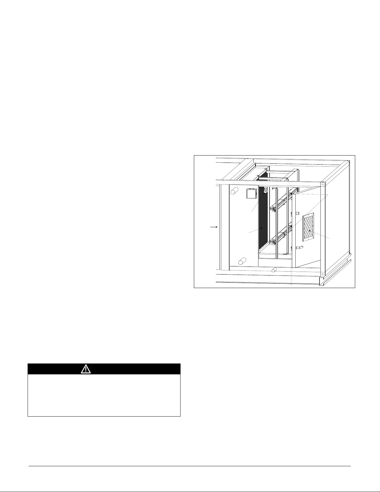
Table of Contents
Viewing
window
Ultra violet
light units
Light power
disconnect
switch
Cooling
coil
Air flow
Introduction.......................................................................................................................................................................................2
Description ........................................................................................................................................................................................2
Operation........................................................................................................................................................................................... 2
Replacing Bulbs ................................................................................................................................................................................3
Removing Lamp Units ......................................................................................................................................................................3
Replacement Parts List......................................................................................................................................................................4
Typical ultraviolet light wiring schematic ........................................................................................................................................ 4
Introduction
This manual provides general information about the
Ultraviolet Light option for McQuay Vision™ Indoor Air
Handler, Models CAH/CAC. In addition to an overall
description of the unit, it includes removal and installation
procedures, maintenance instructions and parts identification.
Description
The ultraviolet light application is designed to irradiate the
coil surface along with the drain pan. Germicidal protection
is delivered at a wavelength of 254 nanometers in the light
spectrum. Light at this wavelength is known as UV-C. Most
bacteria, mold, and virus organisms are killed by exposure to
UV-C light.
Ultraviolet lights are typically installed on the leaving side of
the cooling coils in the unit. Each light module is mounted on
a rail and is removable for convenient bulb replacement.
UV Light Power Disconnect switches are factory installed on
every access panel that allows a direct line of sight to the UV
lamps when opened. These switches are designed to prevent
UV exposure when cabinet access panels are opened and
must not be disabled.
A viewing window near the UV lights allows viewing to
determine if the lights are energized. The viewing windows
use specially designed glass that blocks harmful UV light.
WARNING
UV-C exposure is harmful to the skin and eyes. Looking
at an illuminated UV-C bulb can cause permanent
blindness. UV-C skin exposure can cause cancer.
Always disconnect power to power receptacle before
servicing. Do not operate if disconnect switch has been
disabled.
Figure 1. Typical ultraviolet light installation
Operation
Refer to the wiring schematic on page 4. 115 VAC power for
the UV lights is provided by the field. The lights operate
whenever the unit is powered and all access panel power
disconnect switches are closed. To turn the lights off,
disconnect power to the power receptacle.
The normally open interlock switches are wired in series in a
circuit that supplies 115VAC to the UV lights when all
access panels are closed.
Page 2 IM-808-1
Page 3

Replacing Bulbs
Lamp
Lamp unit
Power
receptacle
Removing Lamp Units
Replace all bulbs every 12 months regardless of condition.
Refer to the manufacturer’s suggested replacement interval.
NOTE: A glowing lamp indicates only that the UV light is
powered, not that it is emitting the necessary UV-C
wavelength for germicidal effect.
WARNING
Personal Injury Hazard. Power supply can cause
electrical shock.
Always disconnect all power to unit before servicing.
WARNING
UV-C exposure is harmful to the skin and eyes. Looking
at an illuminated UV-C bulb can cause permanent
blindness. UV-C skin exposure can cause cancer.
Verify the UV lights are off by using the view window.
WARNING
Florescent bulbs contain mercury, which can cause
personal injury if breathed or ingested.
Use appropriate protective gear to clean up broken bulbs.
1. Disconnect power to the power receptacle before
servicing. Verify the power is disconnected.
2. Before opening the access panels, use the viewing
window to make sure the UV lights are off.
NOTE: Do not open modular UV lamp units. There are no
user serviceable components inside.
1. Before handling, allow lamps to cool for 5 minutes. See
Figure 2 below for lamp unit parts.
Figure 2. Lamp unit parts
2. Unplug the power receptacle from the row of lamps by
pulling it apart from the lamp unit. Then slide the
receptacle off the rail. See Figure 3.
Figure 3. Disconnecting power receptacle
3. Before handling, allow bulbs to cool for 5 minutes.
4. Grasp body of bulb firmly at each end.
5. Rotate bulb 90 degrees in either direction.
6. Remove bulb.
7. Reverse process to install replacement bulb.
8. Wipe bulb with clean cloth and alcohol. Avoid touching
bulb; fingerprints can degrade performance.
9. Dispose removed bulbs in accordance with local
environmental regulations.
IM-808-1 Page 3
Page 4

3. Carefully slide one end of the lamp unit to the notches in
Rail
Notches
NOTE TO FIELD:
Switches are shown with the access panels in the open position.
Lights are on when the access panels are closed and off when the access panels are open.
the rail and pull it out and away from the rail.
4. Slide the other end to the notches and pull it out and away
from the rail.
5. Place the lamp unit on a flat surface.
Figure 4. Removing lamp units from rail
Replacement Parts List
McQuay PN Description
205485001 Power Disconnect Switch
205485101 Actuator Key for Disconnect
205484001 18 in. Lamp Holder
205484101 24 in. Lamp Holder
205484201 36 in. Lamp Holder
205485501 Hard Wire Module
205484501 18 in. Lamp
205484601 24 in. Lamp
205484701 36 in. Lamp
Figure 5. Typical ultraviolet light wiring schematic
This document contains the most current product information as of this printing. For the most up-to-date
product information, please go to www.mcquay.com.
© 2009 McQuay International • www.mcquay.com • 800-432-1342
 Loading...