

Page 1
ALG-6000
Cellular LTE Broadband Router
ALG-6000 Cellular Router
User Manual
Firmware Version 1.0.4.26; September 2015
Page 2

Copyright Notice
©2012 to 2015 Atlas Labs LLC. All Rights Reserved.
Atlas Labs reserves the right to modify the equipment, its specification or this manual without prior notice,
in the interest of improving performance, reliability, or servicing. At the time of publication all data is correct
for the operation of the equipment at the voltage and/or temperature referred to. Performance data
indicates typical values related to the particular product.
No part of this documentation or information supplied may be divulged to any third party without the
express written consent of Atlas Labs. Products offered may contain software which is proprietary to Atlas
Labs. The offer or supply of these products and services does not include or infer any transfer of ownership.
Modem Use
The Atlas Labs ALG-6000 cellular modem is designed and intended for use in fixed, nomadic, or mobile
applications. “Fixed” assumes the device is physically secured at one location and not easily moved to
another location. “Mobile” assumes the modem is physically secured in a vehicle and is operated when the
vehicle is moving. “Nomadic” assumes the modem is installed in a vehicle but is operated when the vehicle is
stationary.
Please keep the cellular antenna of the ALG-6000 router at a safe distance from your head and body while
the modem is in use (see below).
Important
Maintain a distance of at least 20 cm (8 inches) between the transmitter’s antenna and any person while in
use. This modem is designed for use in applications that observe the 20 cm separation distance.
Interference Issues
Avoid possible radio frequency (RF) interference by following these guidelines:
The use of cellular telephones or devices in aircraft is illegal. Use in aircraft may endanger operation
and disrupt the cellular network. Failure to observe this restriction may result in suspension or
denial of cellular services to the offender, legal action or both.
Do not operate in the vicinity of gasoline or diesel-fuel pumps unless use has been approved and
authorized.
Do not operate in locations where medical equipment that the device could interfere with may be in
use.
Do not operate in fuel depots, chemical plants, or blasting areas unless use has been approved and
authorized.
Use care if operating in the vicinity of protected personal medical devices, i.e., hearing aids and
pacemakers.
Operation in the presence of other electronic equipment may cause interference if equipment is
incorrectly protected. Follow recommendations for installation from equipment manufacturers.
Mobile Application Safety
Page 3

Do not change parameters or perform other maintenance of the ALG-6000 while driving.
Road safety is crucial. Observe National Regulations for cellular telephones and devices in vehicles.
Avoid potential interference with vehicle electronics by correctly installing the ALG-6000.
Leveraging the FCC Modular approval of the Cellular and WiFi module requires professional install
to avoid antenna correlation.
Page 4

1. Table of Contents
ALG-6000 ...................................................................................................................................................................................... 1
Cellular LTE Broadband Router .................................................................................................................................................. 1
1. Table of Contents ....................................................................................................................................................... 4
1. Preface ........................................................................................................................................................................... 1
1.1. FCC Notification .............................................................................................................................................................. 1
2. Product Overview ...................................................................................................................................................... 2
2.1. General Description ....................................................................................................................................................... 2
2.2. Features ............................................................................................................................................................................... 2
2.3. External Interfaces .......................................................................................................................................................... 3
2.3.1. Front Panel Connections ..................................................................................................................................... 3
2.3.2. LEDs .............................................................................................................................................................................. 3
2.3.3. Back Panel Connections ....................................................................................................................................... 5
2.3.4. RJ-45 Ethernet Ports ............................................................................................................................................. 6
2.3.5. Power Cable Connections ................................................................................................................................... 6
2.4. Antenna Options .............................................................................................................................................................. 7
2.4.1. Cellular Antennas (Primary & Diversity) ....................................................................................................... 7
2.4.2. GPS Antenna ............................................................................................................................................................. 7
2.4.3. WiFi Antenna ............................................................................................................................................................ 7
2.4.4. A-9 Combination Antennas ................................................................................................................................ 7
2.4.5. Antenna Spacing – Individual Antennas ........................................................................................................ 8
2.4.6. Antenna Placement – A-9 Antennas ............................................................................................................... 9
3. Getting Started ......................................................................................................................................................... 11
3.1. Package Contents ......................................................................................................................................................... 11
Page 5

3.2. Setup Requirements .................................................................................................................................................... 11
3.3. Quick Start ....................................................................................................................................................................... 11
3.3.1. Hardware Setup .................................................................................................................................................... 11
3.3.2. Configuring Local PC .......................................................................................................................................... 11
3.3.3. Cellular Connections .......................................................................................................................................... 11
3.3.4. ALG-6000 Cellular router Setup ................................................................................................................... 12
4. Provisioning the ALG-6000 Cellular Router ................................................................................................... 13
4.1.1. Activation /APN Configuration ...................................................................................................................... 13
5. ALG-6000 Configuration ....................................................................................................................................... 14
5.1. General Instructions .................................................................................................................................................... 14
5.2. Status ................................................................................................................................................................................. 14
5.2.1. System ....................................................................................................................................................................... 16
5.2.2. Basic Settings ......................................................................................................................................................... 16
5.3. WAN ................................................................................................................................................................................... 18
5.3.1. Carrier ....................................................................................................................................................................... 18
5.3.2. Settings ..................................................................................................................................................................... 19
5.3.3. Dynamic DNS ......................................................................................................................................................... 21
5.3.4. System Monitor ..................................................................................................................................................... 22
5.4. LAN ..................................................................................................................................................................................... 23
5.4.1. LAN Settings ........................................................................................................................................................... 24
5.5. WLAN ................................................................................................................................................................................ 25
5.5.1. Status ......................................................................................................................................................................... 26
5.5.2. Access Point............................................................................................................................................................ 26
5.5.3. Client ......................................................................................................................................................................... 28
5.6. Router ................................................................................................................................................................................ 30
Page 6

5.6.1. Port Forwards ........................................................................................................................................................ 31
5.6.2. IP Filtering ............................................................................................................................................................... 32
5.6.3. MAC Filtering......................................................................................................................................................... 35
5.6.4. Static Routes .......................................................................................................................................................... 36
5.6.5. ARP ............................................................................................................................................................................. 37
5.7. Security ............................................................................................................................................................................. 37
5.7.1. Status ......................................................................................................................................................................... 37
5.7.2. PPTP .......................................................................................................................................................................... 38
5.7.3. IPSEC ......................................................................................................................................................................... 40
5.7.4. GRE ............................................................................................................................................................................. 42
5.8. Serial ................................................................................................................................................................................... 43
5.8.1. External Serial ........................................................................................................................................................ 43
5.9. GPS/GNSS ........................................................................................................................................................................ 46
5.9.1. Status ......................................................................................................................................................................... 46
5.9.2. Settings ..................................................................................................................................................................... 47
5.10. Diagnostics ...................................................................................................................................................................... 50
5.10.1. SMS............................................................................................................................................................................. 50
5.10.2. RSSI Traps ................................................................................................................................................................ 53
5.10.3. Syslog Settings ....................................................................................................................................................... 53
5.10.4. System Log .............................................................................................................................................................. 54
5.10.5. Kernel Log ............................................................................................................................................................... 54
5.11. I/O Settings ...................................................................................................................................................................... 54
5.11.1. Status ......................................................................................................................................................................... 55
5.11.2. SNMP ......................................................................................................................................................................... 55
5.11.3. Settings ..................................................................................................................................................................... 57
Page 7

5.12. Admin ................................................................................................................................................................................. 58
5.12.1. Admin – Access ..................................................................................................................................................... 58
5.12.2. Device Outlook ..................................................................................................................................................... 58
5.12.3. Remote Admin ....................................................................................................................................................... 59
5.12.4. Radius ........................................................................................................................................................................ 60
5.12.5. Firmware Update ................................................................................................................................................. 60
5.12.6. System Reset .......................................................................................................................................................... 61
6. Service and Support ................................................................................................................................................ 63
6.1. Product Warranty, RMA and Contact Information ........................................................................................ 63
6.2. RMA Request .................................................................................................................................................................. 63
6.3. Product Documentation ............................................................................................................................................ 63
6.4. Technical Support ......................................................................................................................................................... 63
7. I/O Port Connector ................................................................................................................................................ 64
8. Serial Port Emulation.............................................................................................................................................. 65
8.1. HW VSP3 Configuration ............................................................................................................................................ 65
8.2. ALG-6000 Configuration ........................................................................................................................................... 66
9. Road Safety Integration ......................................................................................................................................... 68
9.1. Prerequisites ................................................................................................................................................................... 68
9.2. Configuration ................................................................................................................................................................. 68
9.2.1. Physical Connection ............................................................................................................................................ 68
9.2.2. ALG-6000 Serial Port Configuration ........................................................................................................... 68
9.2.3. Road Safety Base Station Configuration .................................................................................................... 69
Page 8

1. Preface
1.1. F CC N oti fi catio n
This device complies with part 15 of the FCC rules. Operation is subject to the following conditions: (1) This
device may not cause harmful interference, and (2) this device must accept any interference received,
including interference that may cause undesired operation.
Changes or modifications not expressly approved by the party responsible for compliance could void the
user's authority to operate the equipment.
Note: This equipment has been tested and found to comply with the limits for a Class B digital device,
pursuant to part 15 of the FCC Rules. These limits are designed to provide reasonable protection against
harmful interference in a residential installation. This equipment generates, uses, and can radiate radio
frequency energy and, if not installed and used in accordance with the instructions, may cause harmful
interference to radio communications. However, there is no guarantee that interference will not occur in a
particular installation. If this equipment does cause harmful interference to radio or television reception,
which can be determined by turning the equipment off and on, the user is encouraged to try to correct the
interference by one or more of the following measures:
Reorient or relocate the receiving antenna.
Increase the separation between the equipment and receiver.
Connect the equipment into an outlet on a circuit different from that to which the receiver is
connected.
Consult the dealer or an experienced radio/TV technician for help.
ALG-6000 Series LTE Cellular Router | Page 1
Page 9

2. Product Overview
2.1. G en er al De scrip ti on
The ALG-6000 offers a single, flexible platform to address a variety of wireless communications needs with
over-the-air configuration and system monitoring for optimal connectivity. This ready-to-deploy broadband
router enables wireless data connectivity over public cellular networks including Verizon, T-Mobile, and
AT&T.
This single, flexible platform addresses a variety of wireless communications needs with serial to IP
conversion, over-the-air configuration and system monitoring for optimal connectivity. This ready to deploy
broadband router enables wireless data connectivity for up to two LAN and one serial device over public
cellular networks at LTE speeds.
Equipped for a broad range of fixed applications, the ALG-6000 provides reliable connectivity for
Programmable Logic Controllers (PLCs), Remote Terminal Units (RTUs), Ethernet web cameras or any other
Ethernet or serial device. For mobile applications, this intelligent broadband router incorporates an optional
highly sensitive 16-channel GPS receiver and an intelligent algorithm that offers outstanding receive
sensitivity and improved accuracy, integrity and availability of GPS signals – even when the vehicle is off. A
built-in Wi-Fi access point also allows your tethered devices to remain connected even when you leave the
vehicle.
2.2. F ea tu res
VPN Support using industry standard IPSec protocols
Built-in DHCP server and NAT support
High sensitivity 16 channel GPS receiver
Local and remote configuration via web browser
Dual port 10/100 Ethernet interface
Dual (optional) serial ports
WiFi IEEE 802.11b/g/n 2.4GHz
Built-in WiFi Access Point and Client Modes
Low power ARM9 processor
Analog and Digital I/O – 4 analog inputs, 7 digital inputs, and 7 digital outputs
GPS and GLONASS
ALG-6000 Series LTE Cellular Router | Page 2
Page 10

2.3. E xt er nal I nterf ac es
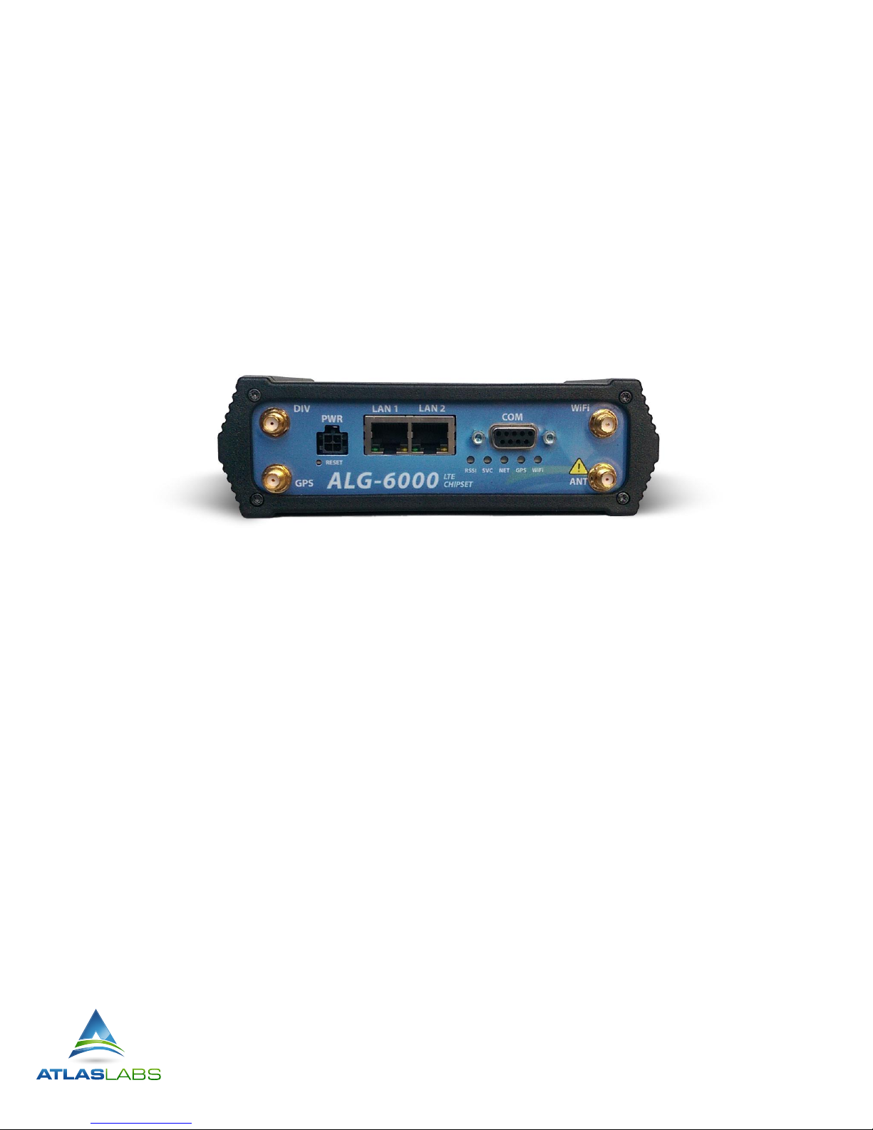
2.3.1. Front Panel Connections
Figure 1. ALG-6000 cellular router’s front panel
The ALG-6000 cellular router’s front panel connections include:
GPS: SMA female, GPS antenna connector. This input requires a 3.3V, GPS antenna with an SMA
connection. For best coverage, use an active GPS antenna with a gain of >25dBm, right hand circular
polarization.
PWR: 9-28 VDC; the mating connector is a Molex 43025-0400 4 position connector.
LAN1 & LAN2: Input for standard or crossover Ethernet cable.
COM: Standard RS-232 port for debugging, GPS, serial-over-ip, and maintenance.
ANT: SMA female, primary cellular antenna connection. See section “Antenna options” for more
information.
DIV: SMA female, cellular receive diversity antenna. See section “Antenna options” for more information.
WiFi: RP-SMA jack, WiFi antenna. See section “Antenna options” for more information.
2.3.2. LEDs
There are five LEDs on the front panel of the ALG-6000 unit. Each can display three colors: Red, Green, and
Amber. The definition for each LED is as follows:
ALG-6000 Series LTE Cellular Router | Page 3
Page 11

LED
OFF
GREEN
FLASHING
GREEN
RED
FLASHING
RED
AMBER
RSSI
No Power
Strong RSSI
N/A
Very Low
RSSI
N/A
Medium or
Low RSSI
SVC
No Service
3G/4G
Attempting
Connection
Attempting
Connection
2G
NET
No
Connectivity
Network
Connected
RX Data
No
Network
Connection
TX Data
RX/TX Data
GPS
Disabled or
No Power
GPS Fix
Valid
Search
No Fix
N/A
Time Sync
WiFi
Disabled or
No Power
Good
N/A
Failure
N/A
N/A
LED behavior is different than listed above when device is booting. The boot sequence is: all red, all green, all
flash green three times, then boot sequence completed.
ALG-6000 Series LTE Cellular Router | Page 4
Page 12
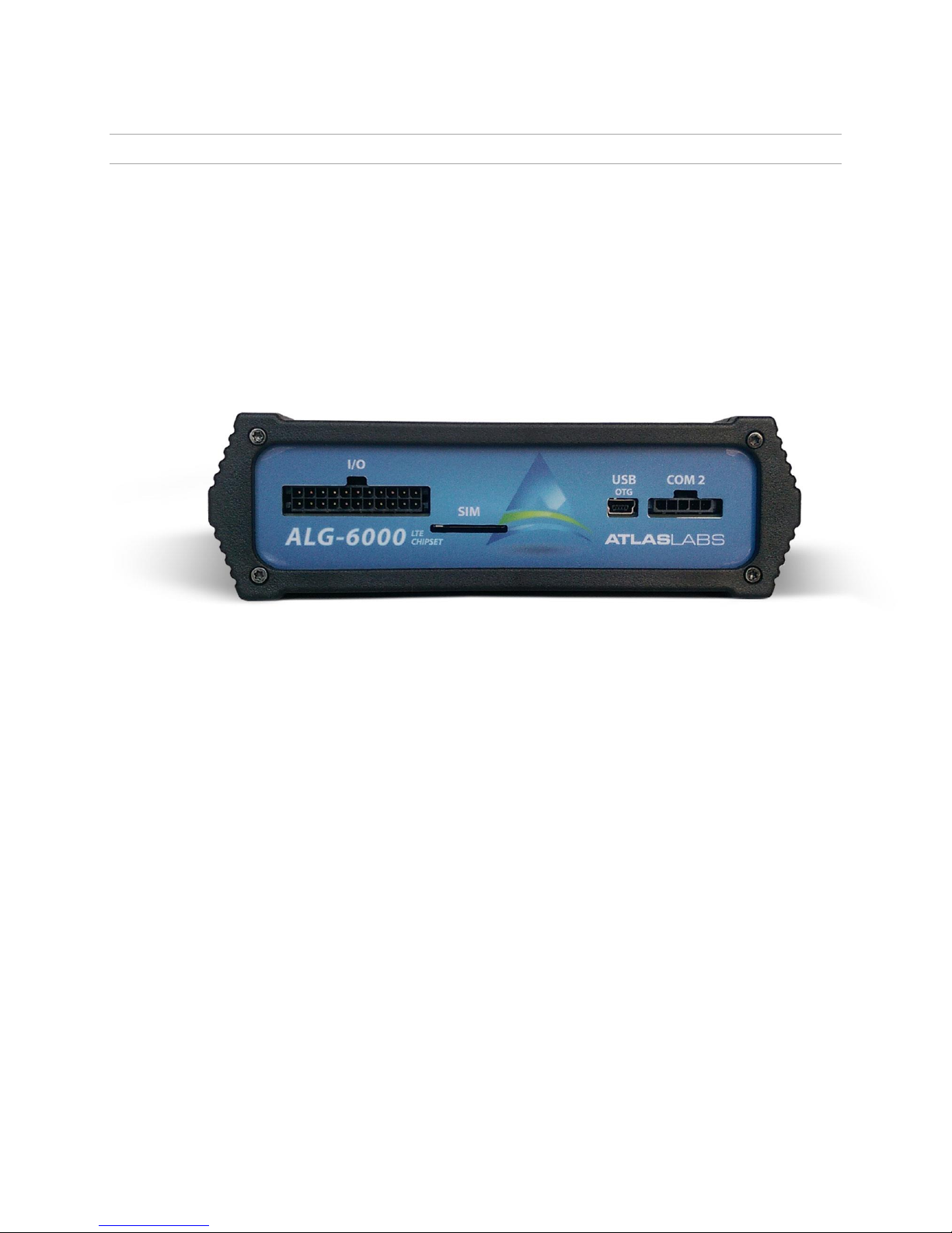
2.3.3. Back Panel Connections
The ALG-6000 cellular router’s back panel connections include:
I/O: I/O interface connector
COM 2: Second serial port (requires interface module)
SIM: Full size (1FF) SIM card slot
USB OTG: USB On-the-Go
Figure 2 - ALG-6000 cellular router’s back panel
ALG-6000 Series LTE Cellular Router | Page 5
Page 13
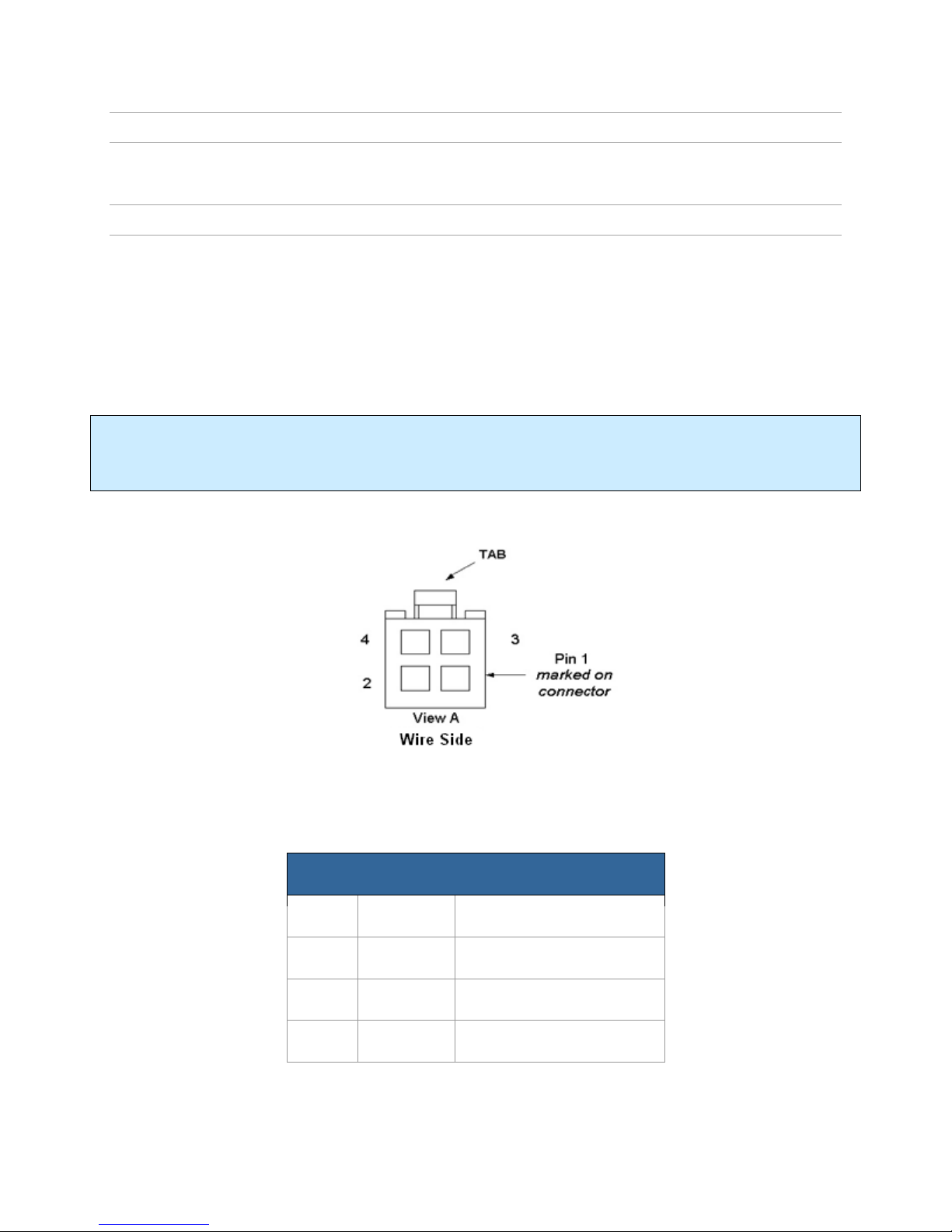
Pin
Color
Description
1
Red
DC Power, 9 to 28V DC
2
Blue
Ground
3
White
Ignition Sense
4
NA
Not Connected
2.3.4. RJ-45 Ethernet Ports
The ALG-6000 cellular router can accept either standard or cross over ethernet cables.
2.3.5. Power Cable Connections
If using the provided power cable to connect to a DC supply (car battery) use the following diagrams and
table to connect the unit.
Ensure the ignition sense line is connected to the vehicle's ignition. This line will initiate the shutdown timer
following ignition deactivation (if enabled).
Note: Both ignition sense and DC power are required to start up an ALG-6000.
Caution: Connect the red power wire to a CONSTANT hot source. To prevent corruption of the ALG-6000
firmware, only use the ignition source to power off the unit.
Figure 3 - ALG-6000 power cable connections
ALG-6000 Series LTE Cellular Router | Page 6
Page 14

2.4. A nt en na Op tions
Antennas are available for ALG-6000 cellular router installations from Atlas Labs.
2.4.1. Cellular Antennas (Primary & Diversity)
Primary cellular antenna connections are SMA female connectors and must be used with antenna with SMA
male connectors. When using a direct mount or rubber duck antenna, choose the antenna specific to your
band requirements. Mounting options and cable lengths are user’s choice and application specific, though
Atlas Labs recommends using the shortest possible cable length to minimize signal loss.
The ALG-6000 cellular router RX Diversity antenna has the same requirements as the primary antenna.
Mounting options and cable lengths are the user’s choice and application specific, though cables runs should
be the shortest possible length. For best performance, separation between the Primary and Diversity
antenna should be at least 5/8 wavelength (~10 inches for 700 MHz).
Caution: To comply with FCC approval for this device, do not use a cellular antenna with a gain greater than
5 dBi in the cellular (800MHz) band, or 4 dBi in the 1900MHz band.
2.4.2. GPS Antenna
The ALG-6000 cellular router’s GPS connector requires an external 3.3V GPS antenna. The GPS antenna
connection on the ALG-6000 product is a female SMA connector; therefore an antenna with an SMA male
connector is required. For best coverage, use an active antenna with a gain >25dB and right-hand circular
polarization. Mounting options and cable lengths are user’s choice and application specific, though cable
lengths should be as short as possible for minimal signal loss.
2.4.3. WiFi Antenna
The WiFi antenna connection on the ALG-6000 product is an RP-SMA jack; therefore an antenna with an
RP-SMA plug is required. Mounting options and cable lengths are user’s choice and application specific,
though cable lengths should be as short as possible for minimal signal loss.
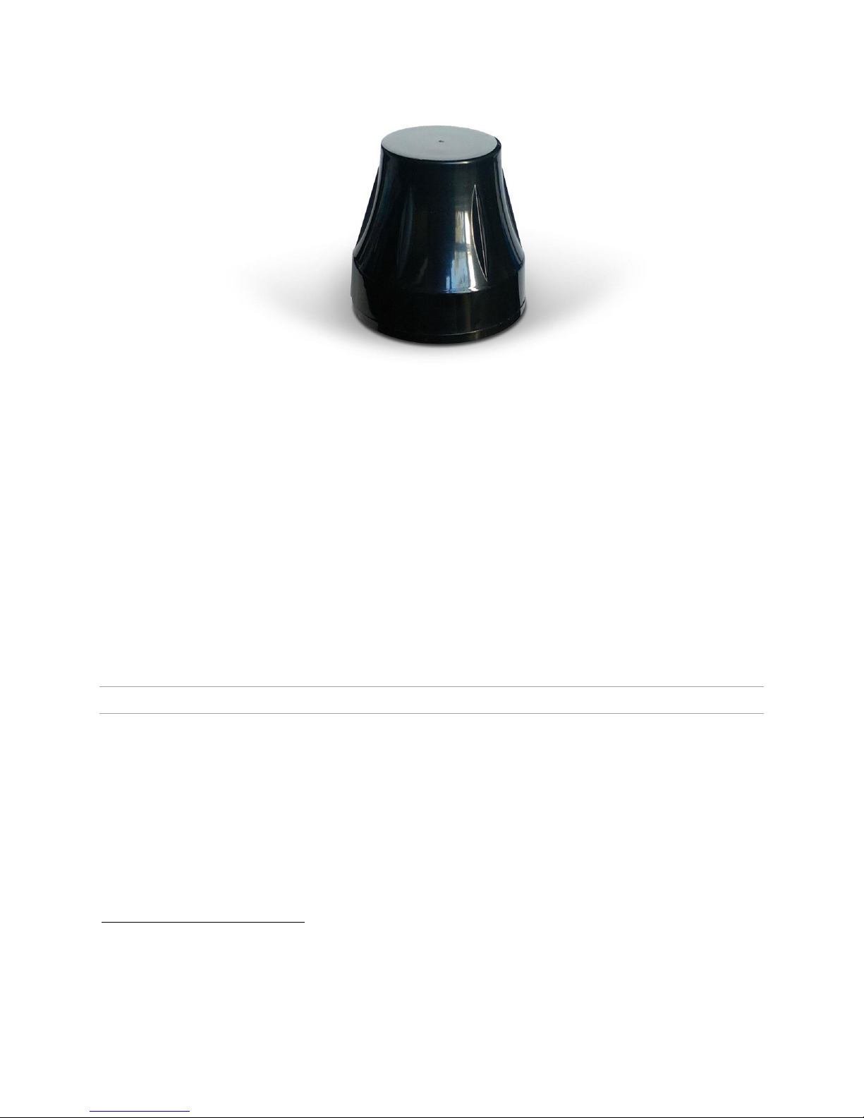
2.4.4. A-9 Combination Antennas
Combination antennas may be used with the ALG-6000 to reduce antenna surface area needed for
installation. The Atlas Labs A-9 Antenna combines three antennas into one with for cellular, WiFi, and GPS
in one enclosure. Two A-9 antennas are recommended for each ALG-6000 with the first A-9 antenna
serving the primary cellular connection, WiFi, and GPS. The second A-9 antenna attaches to the Receive
Diversity port and leaves the spare GPS and WiFi connections available for additional equipment such as
the ALC-1000 in-vehicle touchscreen computer.
ALG-6000 Series LTE Cellular Router | Page 7
Page 15
1
2
1
2
Figure 4 - Atlas Labs A-9 Combination Cellular + WiFi + GPS Antenna.
For the A-9 antenna, the following connections are suggested:
1. Antenna 1:
a. GPS Lead (SMA connector) ALG-6000 GPS Port
b. WiFi / Bluetooth Lead (RP-SMA connector) ALG-6000 WiFi Port
c. Cell Lead (SMA connector) ALG-6000 ANT Port
2. Antenna 2:
a. GPS Lead (SMA connector) No connection
b. WiFi / Bluetooth Lead (RP-SMA connector) No connection
c. Cell Lead (SMA connector) ALG-6000 DIV Port
When used in conjunction with the ALG-6000, the second A-9 antenna will have both the GPS and WiFi
leads unused.
2.4.5. Antenna Spacing – Individual Antennas
Referring to Figure 5 for illustration, the ALG-6000 cellular router commonly uses four separate antennas
when not used with Atlas Labs A-9 antennas:
“T” - Main transceiver - Constraints are the limit of 20 cm and omni-directional factors
“R” - Auxiliary receiver – Constraints are the receiver spacing of at least 5/8 λ (wavelength) from
transceiver antenna and omni-directional requirements
“G” - Global Positioning System (GPS) - Constraints are TX spacing of at least 60cm/23.62 inch from
all transmitting antennas and a clear view of the sky.
“W” – WiFi antenna - Constraints are TX spacing of at least 8 inches or 20 cm from all transmitting
antennas
The spare GPS antenna lead may be routed to the vehicle dashboard and used in conjunction with the ALC-
1000 In-Dash Computer, provided the antenna lead length is sufficient.
The spare WiFi antenna lead may be routed to the vehicle dashboard and used in conjunction with the
ALC-1000 In-Dash Computer, provided the antenna lead length is sufficient.
ALG-6000 Series LTE Cellular Router | Page 8
Page 16
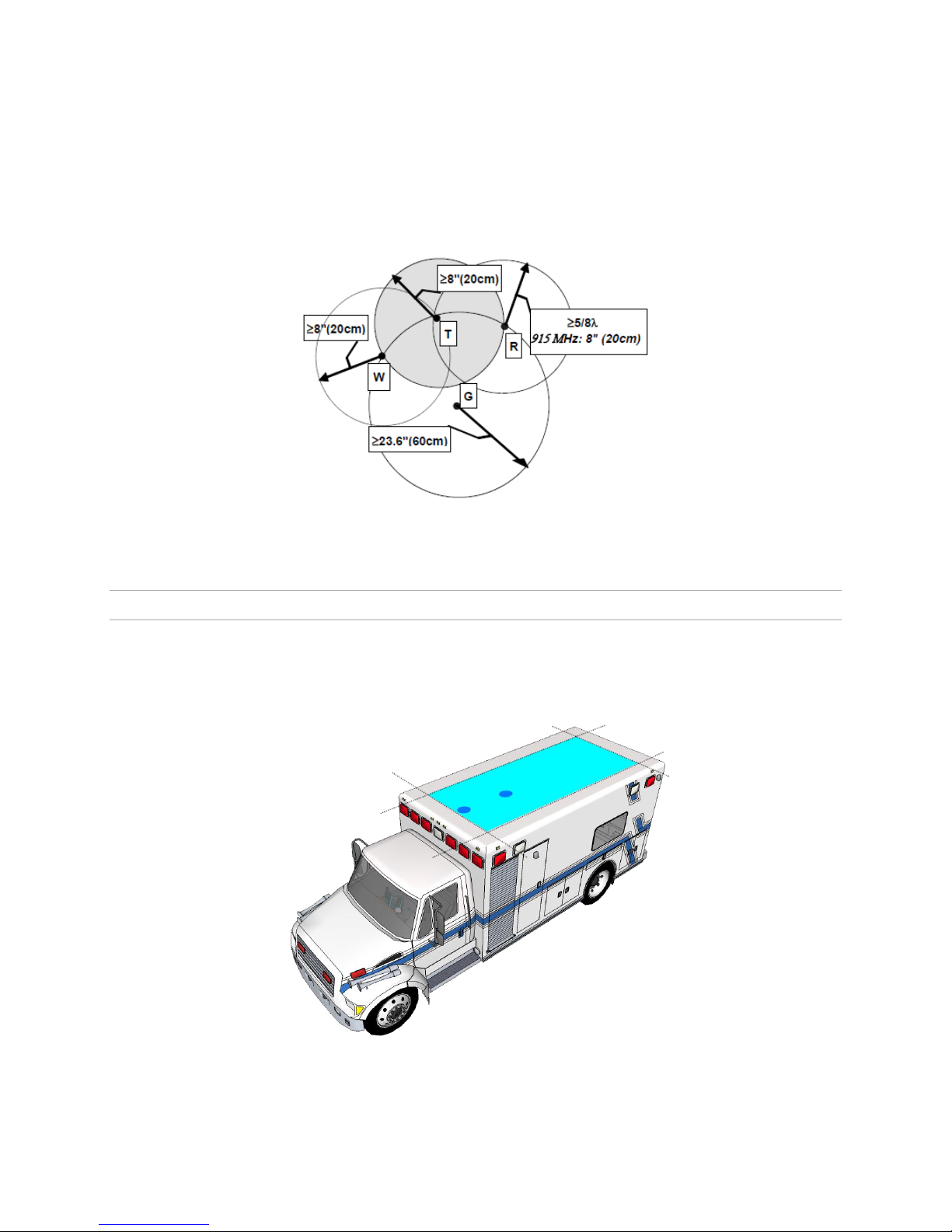
Note: Best overall operation is achieved utilizing antennas with equal gains.
WARNING: As per FCC rules, all ALG-6000 transmitting antennas (T & W) should be at a minimum of eight (8)
inches (approximately 20 centimeters) from all persons.
Figure 5. Antenna Spacing (T: primary antenna, R: diversity antenna, W: WiFi antenna, G: GPS antenna)
2.4.6. Antenna Placement – A-9 Antennas
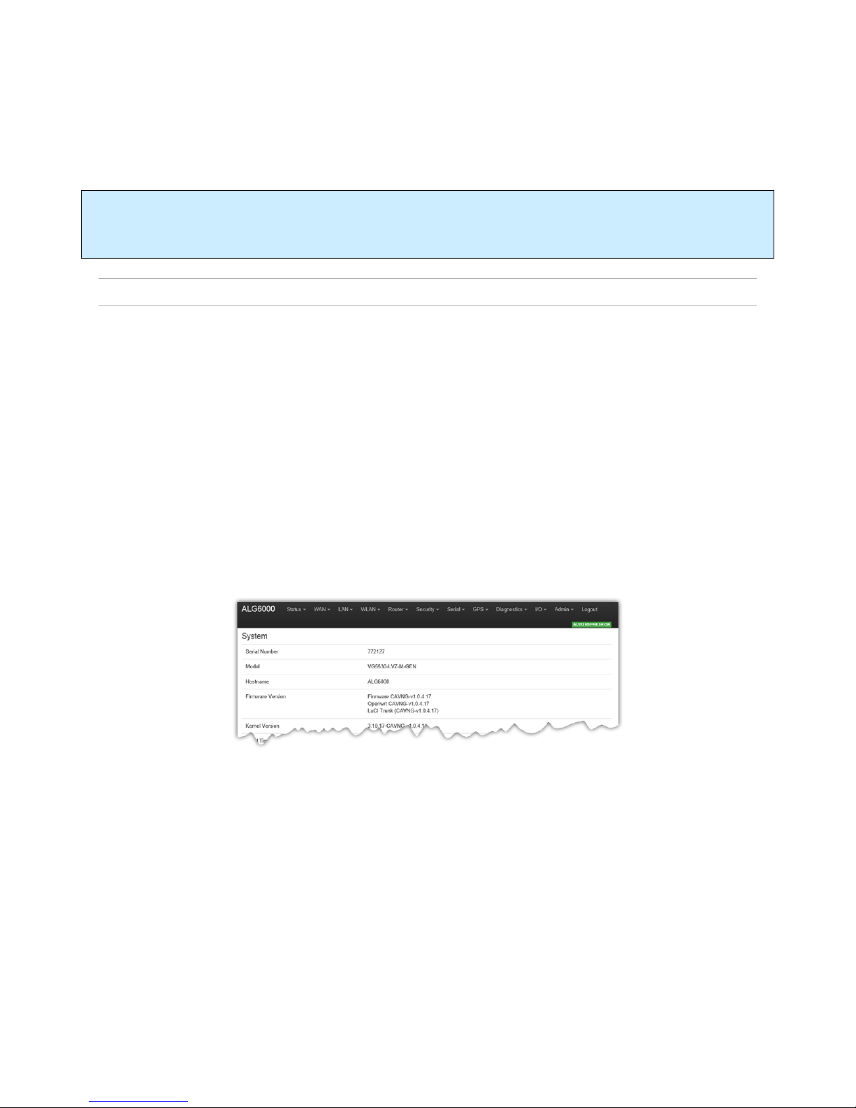
When using Atlas Labs A-9 Antennas, optimal placement is along the centerline of the roof, in a position
resulting in the shortest cable length possible. Maintain at least 8” separation between antennas.
Figure 6. Optimal placement when using two A-9 antennas.
ALG-6000 Series LTE Cellular Router | Page 9
Page 17

For installation of ground-plane dependent antennas (main cellular and WiFi antennas), the center of the
metal surface used for mounting is preferable for best omni-directional pattern. For ground-plane
independent antennas (diversity and GPS antennas), installation may be close to the edges of the surface.
For vehicular installations Atlas Labs recommends the following antenna positions:
Most preferred for all antennas: centerline of roof. For transmitter antenna, it is the ONLY
acceptable position.
Less preferred for receiver antenna: trunk lid, providing distance to transmitting antenna is
respected whether lid is opened or closed.
Much less preferred, but permissible for receiver antenna: left or right rear fenders, just in back of
rear window
Least preferred, but permissible for receiver antenna: left or right front fenders, ahead of
windshield
ALG-6000 Series LTE Cellular Router | Page 10
Page 18

3. Getting Started
3.1. P ac ka ge Co ntent s
ALG-6000 cellular modem
Power cable and Fuse
Mounting Bracket and Screws
3.2. S et up Re qu ire me nt s
ALG-6000 cellular router
Computer running any operating system
9 to 28 Volt power supply
Ethernet cable*
Active cellular data account with full size (1FF) SIM
Cellular antenna with male SMA connector*
Cellular Diversity Antenna (SMA Male) *
GPS Antenna (SMA Male) *
WiFi Antenna (RP-SMA Plug) * ( if applicable)
*These accessories are available from Atlas Labs. Atlas Labs A-9 Combination antenna recommended, but
not required.
3.3. Q ui ck St ar t
3.3.1. Hardware Setup
1. Connect the primary cellular antenna to the ANT connector on the front of the unit. For units
utilizing diversity, install RX Diversity antenna on SMA connector. Connect the GPS antenna to the
GPS connector. For units utilizing WiFi, connect the WiFi antenna to the WiFi connector.
2. Connect an Ethernet cable from the LAN connector of the ALG-6000 unit to the PC. If multiple PCs
are being used, connect the ALG-6000 unit to an Ethernet switch or hub connected to the PCs.
3. Insert the cellular provider SIM card in the SIM slot with the metallic pads facing upward.
4. Connect a power supply cable to the PWR connector of the ALG-6000 unit. Do not power the unit
on yet.
3.3.2. Configuring Local PC
1. Verify network settings on local PC are set to automatically detect IP and DNS server. The path to
network settings varies with the version of Windows you are using.
2. Select the appropriate network connection, typically the Local Area Connection -> right click on the
connection and select “Properties”
3. Select “Internet Protocol (TCP/IP)" properties.
4. Verify that "Obtain an IP address automatically" and "Obtain DNS Server address automatically"
are selected.
3.3.3. Cellular Connections
ALG-6000 Series LTE Cellular Router | Page 11
Page 19
Before you begin, you will need an active cellular account with the carrier of your choice.
Insert the carrier provided SIM card with the gold side up into the SIM slot in the rear of the device. Push the
card completely into the slot until it clicks in place.
Do NOT replace the SIM card while power is applied to the ALG-6000. Inadvertent contact with metallic
internal components may cause a short circuit, resulting in permanent damage to your equipment.
3.3.4. ALG-6000 Cellular router Setup
1. Power on the ALG-6000 cellular router with 9-28VDC 15-Watt supply.
2. In an Internet browser, enter http://192.168.1.50. This will bring up the ALG-6000 product login
page (Note: It may take 30 seconds from initial power-up for the homepage to be available.)
Login to the device
Default Values:
User logon: admin
password: password
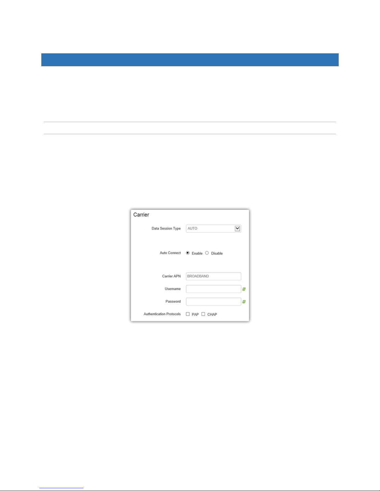
3. This brings up the ALG-6000 product homepage shown below. The configuration options are
further explained later in this document.
ALG-6000 Series LTE Cellular Router | Page 12
Page 20
4. Provisioning the ALG-6000 Cellular Router
IMPORTANT NOTE:
The ALG-6000 cellular router requires an active cellular data service contract for provisioning. Verify that
your cellular service contract is a data service contract with packet data NOT circuit switched technology. If
you do not have an active data contract, contact your service provider.
4.1.1. Activation /APN Configuration
The ALG-6000 typically does not need further action following insertion of a valid SIM in order to establish
a data connection. In some cases however, the network provider may require configuration of a specified
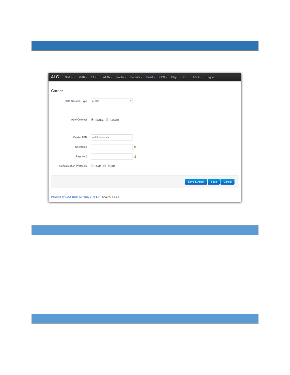
APN. To change the APN, log into the device as outlined in the previous section, then select WAN > Carrier
from the navigation menu to bring up the following screen.
Enter the carrier specified APN in the Carrier APN field, then click the Save & Apply button. Please wait
approximately 30 seconds for the changes to take effect.
Figure 7. Carrier APN settings screen.
ALG-6000 Series LTE Cellular Router | Page 13
Page 21
5. ALG-6000 Configuration
This section explains status information and configuration options available on all HTML pages.
Figure 8. ALG-6000 User Interface.
5.1. G en er al In struc ti ons
The following instructions are common to all HTML pages
Save & Apply: Most changes to a configuration parameter require the user to click Save & Apply before the
change will take effect.
Save: When changing multiple parameters, the user may select Save for each page, then reboot
the device for changes to take effect.
Cancel: Most configuration menus also have a “Cancel” option. Selecting this button will restore all
fields in a section to their last saved value. Note: This does not return them to their factory
defaults.
5.2. S ta tu s
ALG-6000 Series LTE Cellular Router | Page 14
Page 22
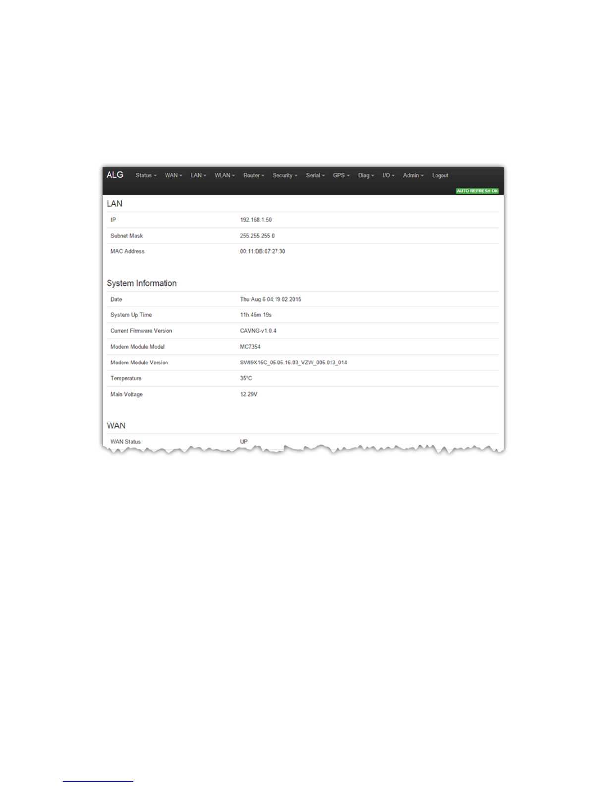
The ALG-6000 cellular modem home page lists the unit’s primary operating parameters and status.
Configuration changes cannot be made from this page.
The status is the first page displayed when navigating to the ALG-6000 Web interface and is the home page
of the device’s web interface. Select Status from the top navigation pane to return to this page. From this
page you can view Status or Identity information or access Basic Settings of the modem.
Figure 9. Status page of the ALG-6000.
ALG-6000 Series LTE Cellular Router | Page 15
Page 23

5.2.1. System
System
The system information section displays information pertaining to general firmware and unit information.
Serial Number – Router serial number
Model – Hardware variant of the router
Hostname – Current hostname assigned to the router
Firmware Version – Version information for various modules of the ALG-6000
Kernel Version – Version of currently running device OS
Local Time – Current time observed by the router. Source may be from GPS module or NTP server.
Uptime – Duration router has been powered up. This will reset for each power cycle or reboot of
the ALG.
Load Average – Average load on device resources over the last 1 minute, 5 minutes, and 15
minutes.
Memory
The current memory usage, broken out into Total Available, Free, Cached, and Buffered categories
DHCP Leases
List of IPv4 and IPv6 leases given out to clients on the wired or wireless LAN interfaces by the DHCP server.
Associated Stations
Currently bounded access point information.
MAC-Address - MAC-address of clients which is connected.
Network - SSID of clients which is connected.
Signal – Signal strength of AP.
Noise - The noise level indicates the amount of background noise in the environment.
RX Rate - Rx Rate is the rate at which packets are received from router.
TX Rate - Tx Rate is the rate at which packets are sent from router.
5.2.2. Basic Settings
The Basic Settings page, under the Status navigation item enables configuration of the following:
ALG-6000 Series LTE Cellular Router | Page 16
Page 24
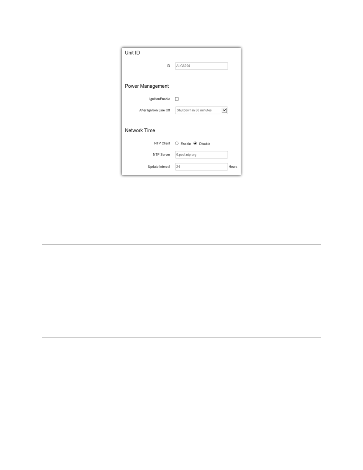
Figure 10. Basic Settings under the Status menu item.
5.2.2.1. Unit ID
ID – Identifier used when reporting GPS and other data to remote servers. If used for TAIP with ID
reports, the first 8 characters should consist of letters and digits only, no special characters.
5.2.2.2. Power Management
Depending on power cabling, the router may stay ON regardless of whether the vehicle ignition is on. The
unit can be configured to automatically shut down 1, 5, 30, 60, 120 or 240 minutes after ignition has been
turned off.
Leaving the unit live allows the driver to use the modem without idling the vehicle and defining a shut-off
time limit prevents the modem from draining the battery when the vehicle is unoccupied.
Ignition Enable – Disabled by default. Select Power Off to enable power management.
After Ignition Line Off – Select a time limit for the router to power down following ignition shut off
5.2.2.3. Network Time
The ALG-6000 is capable of maintaining the current time (UTC) by synchronizing itself with a Network Time
Protocol (NTP) Server. You may specify a server URL and how frequently the router should synchronize
with the server. The router must have an internet connection to synchronize with the server. The router
does not save or track time while powered off, so time will be inaccurate until the router can connect with
the server, which it does on startup (in addition to synchronizing according the Update Frequency specified).
NTP Client – Disabled by default. Select Enabled to activate the router’s NTP client for sync with
the specified server.
ALG-6000 Series LTE Cellular Router | Page 17
Page 25
NTP Server – Enter the URL of the desired NTP server. Most NTP servers have a posted usage
policy. A review of usage policies and the choice of an appropriate server is recommended.
Update Interval – Specify the frequency to synchronize the router time with the configured NTP
server. By default, synchronization is set to 24 hours.
5.3. W AN
This page contains the provisioning information and the carrier activation settings. For more information on
the procedure for carrier activation, see “Provisioning the ALG-6000 Cellular router”.
5.3.1. Carrier
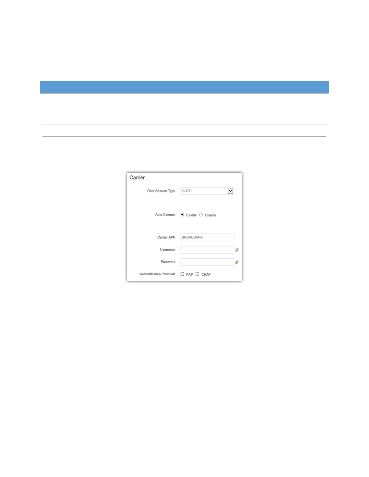
The Carrier tab enables you to configure the carrier (cellular provider) and credentials to be used for data
calls.
Data Session Type – Select Auto, 4G, 3G, or 2G.
Auto Connect – Select Enable (the default recommended setting), and the modem will
automatically dial the connection at startup, and to attempt reconnection if the connection is lost.
Select Disable to prevent the modem automatically connecting at startup. When disabled, a button
will be displayed that can be used to manually connect or disconnect the wireless WAN service.
If Auto Connect is enabled and the modem fails to connect, the unit will attempt to reconnect two times and
then make an attempt at one minute, at two minutes, at eight minutes, and then every fifteen minutes until
successful.
Carrier APN - The Access Point Name required by the cellular provider to access the network. This
value may determine if the router receives a publicly routable WAN address. Enter the APN
provided by the carrier.
ALG-6000 Series LTE Cellular Router | Page 18
Page 26
Username - Username required by the cellular provider. Leave blank if not required. CAUTION: If
used in combination with this router’s VPN server, this user name and password (below) will also be
valid on this router’s VPN server.
Password - Password required by the cellular provider. Leave blank if not required. See the Caution
message associated with the User field above.
Authentication Protocols - Configure the authentication protocol to be used, or none. If no
protocol is selected (the default and recommended setting for most applications), the router will try
to negotiate a protocol with a cell tower, if the cellular carrier allows negotiation. If a protocol is
selected, then the router will only accept requests for the specified protocol(s), where PAP is
Password Authentication Protocol and CHAP is Challenge-Handshake Authentication Protocol.
o PAP – The Password Authentication Protocol is a pre-shared key method for
authenticating with the cellular provider.
o CHAP – The Challenge-Handshake Authentication Protocol is a two-way authentication
scheme between router and provider.
Note: Normally the cellular provider does not require a username or password, in which case leave the
Username and Password fields blank. SIMs from some carriers for special applications may require username
and password settings to establish WAN connections on the cellular network.
5.3.2. Settings
The carrier settings displayed on this page differ depending on which carrier is being used at the time.
One of the key features of LTE is the Subscriber Identity Module (SIM), commonly known as SIM card. The
SIM is a detachable smart card containing the user’s subscription information. This allows the user to retain
his or her information when switching handsets or wireless devices, independent of which handset or
wireless device they are using.
Figure 11. WAN Settings.
ALG-6000 Series LTE Cellular Router | Page 19
Page 27

The SIM has a security feature which, when enabled, requires the user to enter a valid PIN before the
modem will connect to the cellular network.
5.3.2.1. SIM Status
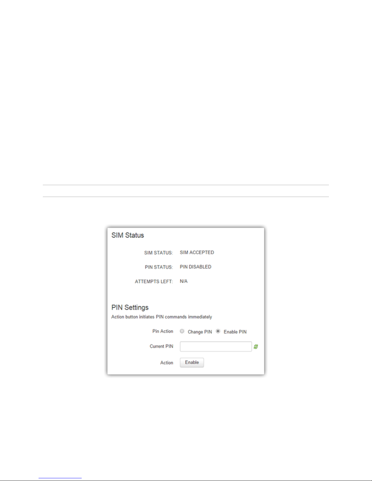
The Current Status section displays the current status of the SIM (whether a SIM card is present, and if so
whether it is valid) and PIN (whether a PIN has been entered and PIN security enabled).
SIM Status – SIM ACCEPTED displays when a valid SIM card is inserted properly in the router. NO
SIM displays if the SIM card is invalid, missing, or installed incorrectly.
PIN Status – PIN DISABLED displays when PIN security is not enabled. PIN ENABLED displays when
PIN security is enabled. PIN ACCEPTED displays when PIN security is enabled and a valid PIN is
entered.
Attempts Left – Indicates the number of attempts remaining to correctly enter the PIN before the
SIM is locked. Maximum number of attempts is three. If SIM is locked, you must contact your
cellular provider to unlock.
5.3.2.2. PIN Settings
The Pin Settings section enables you to enter a PIN, change a pin, enable PIN security or disable it.
Instructions for the available actions and associated options displayed in this section of the Web page
change depending on the SIM status, whether a PIN has been entered, and whether PIN security is enabled
or disabled.
The default setting for PIN security is disabled and you will see the status message “Action: PIN is disabled.
To change it, it must be enabled first.”
Note: Before enabling PIN security, make sure you have the PIN provided by your wireless carrier.
To enter the PIN provided by your wireless carrier (for a new modem)
Change Enable PIN from No to Yes, enter your carrier-provided PIN into the Current PIN field, and click Save
to access the PIN security settings.
To change your PIN or change PIN security settings
Change PIN from Yes to No, enter your PIN into the Current PIN field, and click Save to access the PIN
security settings.
To Change the PIN Status
Once the PIN has been entered successfully, the status message displays “Action: You may change only one
of the following three options at a time,” and three options are presented.
Remember PIN (Enter Current PIN) Yes / No
o To have your PIN remembered (not need to be entered each time to establish connection),
select Yes.
o To not enable this feature (not having your PIN remembered), select No.
o Enter your PIN in the Current PIN field and click Save to make your selection take effect.
Disable PIN (Enter Current PIN) Yes / No
ALG-6000 Series LTE Cellular Router | Page 20
Page 28
o To disable PIN security, select Yes.
o To enable PIN security, select No.
o Enter your PIN in the Current PIN field and click Save to make your selection take effect.
Change PIN (Enter Current PIN, New PIN, and Confirm PIN) Yes / No
o To change your PIN, select Yes. Enter your PIN in the Current PIN field, enter your new PIN
in the New PIN field, and enter your new PIN again in the Confirm New PIN field. (The PIN
you enter in the New PIN and Confirm New PIN fields must match exactly.)
Note: If you enter too many or too few characters, or characters that are not allowed in a
PIN, rules for valid PIN length and character selection are displayed.
o To not change your PIN, select No.
o Click Save to make your selection take effect.
When you have made and saved your change successfully, the PIN Status text changes accordingly,
reflecting the change you made.
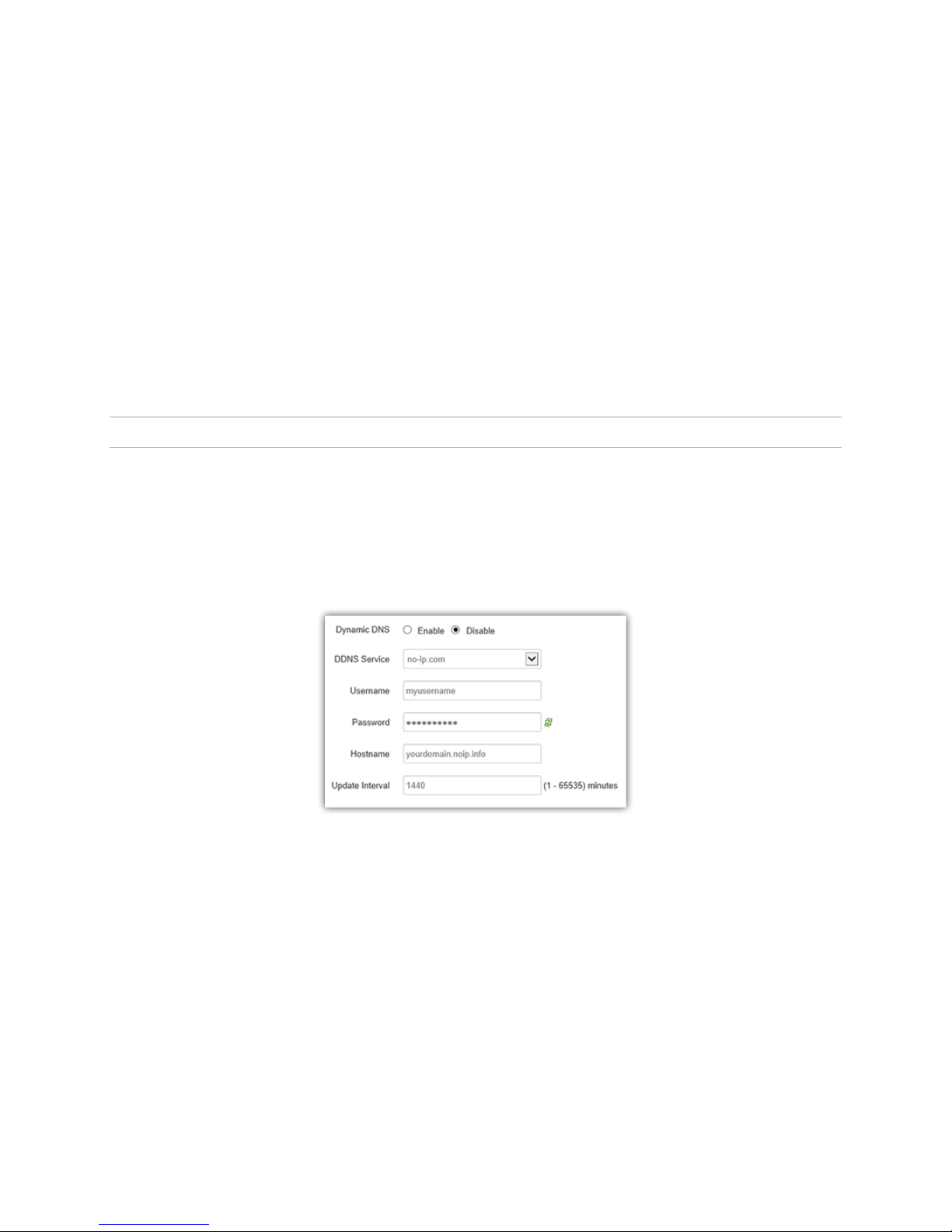
5.3.3. Dynamic DNS
Dynamic DNS is a system which allows the domain name data of a computer with a varying (dynamic) IP
addresses held in a name server to be updated in real time in order to make it possible to establish
connections to that machine without the need to track the actual IP address themselves at all times. A
number of providers offer Dynamic DNS services ("DDNS"), free or for a charge. For example, a free service
provided by NO-IP allows users to setup between one and five host names on a domain name provided by
NO-IP. No-IP is the default DNS service.
Figure 12. Dynamic DNS Configuration Settings.
Dynamic DNS – Selecting Enable will allow the router to provide the select service dynamic IP
address information. Selecting Disable will stop any IP information from being sent to the selected
service.
DDNS Service – The internet address to communicate the Dynamic DNS information to. Default is
no-ip.com.
Username – The username used when setting up the account. Used to login to the Dynamic DNS
service.
Password – The password associated with the username account.
Hostname – The hostname identified to the Dynamic DNS service. For example,
alg6000.atlaslabs.io.
Update Interval – Sets the interval in minutes (0 to 65,535) that the router will update the Dynamic
DNS server of its carrier assigned IP address. It is recommended to set this interval as long as
ALG-6000 Series LTE Cellular Router | Page 21
Page 29
necessary. Each update is considered a data call by the cellular provider and could deplete low
usage data plan allowances.
5.3.4. System Monitor
The System Monitor section allows access to the configuration of additional self-monitoring for the router
to determine when service provider connections may have been terminated.
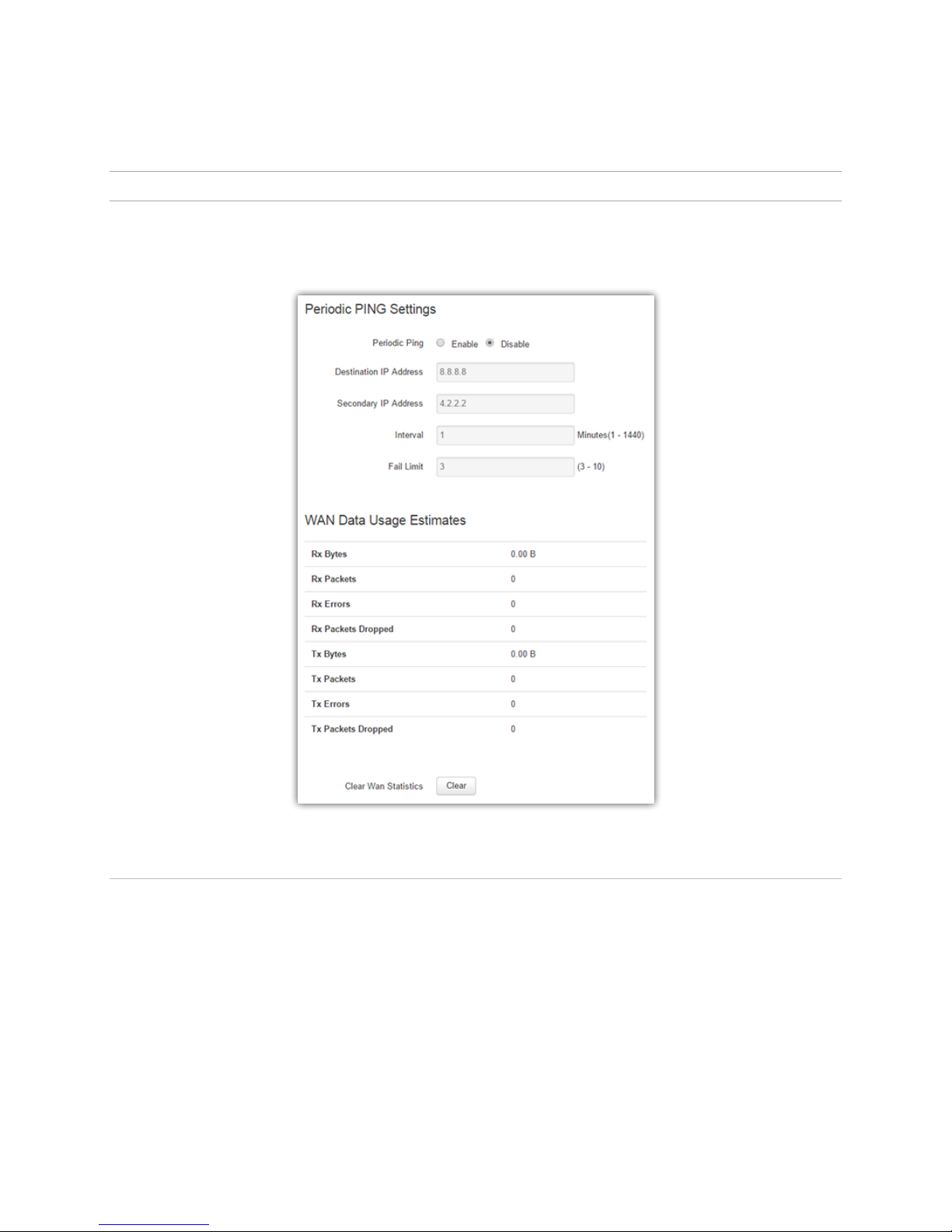
5.3.4.1. Periodic PING Settings
This section allows you to set up a periodic Ping test and specify a failure limit above which the modem will
reset.
Period Ping Enable/Disable – Default setting is disabled.
Destination IP Address – User may enter an accessible IP address or domain name that will
respond to a ping command.
Secondary IP Address - User may enter an accessible IP address or domain name that will respond
to a ping command. This address will be used if the entered number of consecutive ping failures
using the first address is reached.
Interval - Time (in minutes) to wait between pings.
Figure 13. WAN - System Monitor
ALG-6000 Series LTE Cellular Router | Page 22
Page 30

Fail Limit - Number of ping failures to accept before resetting the modem.
5.3.4.2. WAN Data Usage Statistics
This section tracks the data received from and transmitted to the cellular network. This is a tool that may be
used to estimate network usage. These totals are tracked by the router. Your carrier maintains separate
statistics from which your billing is determined. One way to use this tool is to track usage over a fairly short
period of typical usage. The total then can be extrapolated to estimate longer time periods. This router
updates these statistics once approximately every 30 seconds. Press the Clear button to reset the totals to
0.
Rx Bytes - The total number of bytes received by the modem from the cell network. All statistics
will be cleared automatically if this count exceeds 1 billion (1,000,000,000).
Rx Packets - The total number of TCP and UDP packets received by the modem from the cell
network.
Rx Errors - The number of corrupted TCP and UDP packets received by the modem from the cell
network.
Rx Packets Dropped - The number of TCP and UDP packets received by the modem from the cell
network that were not accepted. This may occur due to memory or throughput problems.
Tx Bytes - The total number of bytes transmitted by the modem to the cell network. All statistics
will be cleared automatically if this count exceeds 1 billion (1,000,000,000).
Tx Packets - The total number of TCP and UDP packets transmitted by the modem to the cell
network.
Tx Errors - The number of corrupted TCP and UDP packets received by the modem that were
meant to be transmitted on the cell network.
Tx Packets Dropped - The number of TCP and UDP packets received by the modem for transmit to
the cell network that were not accepted. This may occur due to memory or throughput problems.
Click Clear WAN Statistics to reset the totals to 0. These totals are NOT cleared by a modem reboot.
5.4. L AN
Select LAN from the main navigation pane for access to the LAN Settings section.
ALG-6000 Series LTE Cellular Router | Page 23
Page 31
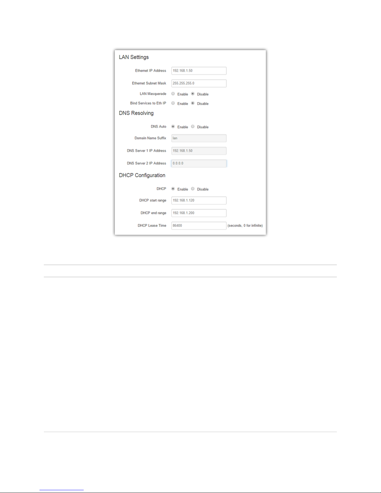
Figure 14. LAN Settings.
5.4.1. LAN Settings
Ethernet IP Address - This sets the IP address of this device and is the address used to access the
configuration pages. If the IP address changes you will have to re-enter the new IP address in your
browser to access the configuration pages. The default IP is 192.168.1.50 and should be changed
for security purposes.
Ethernet Subnet Mask – Sets the subnet mask for the LAN side of the modem to the device.
Important: The LAN subnet mask must not overlap with the WLAN subnet defined in the Access Point tab
of the WLAN page.
LAN Masquerade - When enabled, the router masquerades all Ethernet traffic to the LAN, making
all WAN traffic appear as if it originated from the router. This can be useful in applications where
less-capable equipment on the local LAN cannot cope with connections from multiple Host IP
addresses.
Bind Services to Eth IP - UDP datagrams or TCP sockets from services inside the router (Serial, IO,
GPS) normally appear to come from the interface (LAN or WAN) closest to the destination. Enable
this option to force the source address to be the LAN Ethernet IP address. This can be useful if
packets are being sent through a VPN tunnel. Note that outside of a tunnel, NAT may still force the
source address to be rewritten to the WAN address.
5.4.1.1. DNS Resolving
ALG-6000 Series LTE Cellular Router | Page 24
Page 32

DNS Auto - When enabled, the ALG-6000 masquerades all Ethernet traffic to the LAN, making all
WAN traffic appear as if it originated from the ALG-6000. This can be useful in applications where
less-capable equipment on the local LAN cannot cope with connections from multiple Host IP
addresses.
Domain Name Suffix - The DNS suffix to be assigned by the DHCP server.
DNS Server 1 IP Address - IP address of the preferred DNS server. This value is automatically set
when DNS Auto is enabled.
DNS Server 2 IP Address - IP address of the alternate DNS server. This value is automatically set
when DNS Auto is enabled.
5.4.1.2. DHCP Configuration
DHCP - (Dynamic Host Configuration Protocol) A protocol used by client devices that are
connected to the LAN port of this device to automatically obtain an IP address assigned by this
server/router. Selecting Enable will configure this device to assign IP addresses to client devices
taken from a pool specified by the values entered in DHCP start range and DHCP end range. If
DHCP is set to Disable, the information must be entered manually on all PCs.
DHCP start range – DHCP server starting IP address. Default is set as 192.168.1.120.
DHCP end range – DHCP server ending IP address. The maximum usable number is 253. The
default is set to 192.168.1.200.
DHCP Lease Time - Sets the duration, in seconds, the connected device is allowed to keep the
assigned IP address. In many cases it is possible for the device to receive the same IP address after
the lease time expires. The default is set to 86400 seconds (1 day).
5.4.1.3. Disabling DHCP Server
When DHCP server is enabled, any PC with physical access to the ALG-6000 Ethernet port will be assigned
an IP address and have access to browse the Internet. This may cause security problems. Disabling DHCP
server will allow the user to control which PCs have the ability to connect through the ALG-6000 cellular
router. If changes are made to the network settings, be sure to keep a record of the changes for future use.
Disabling DHCP server is performed on the LAN settings page. Under the DHCP section, select
Disable, then click Save & Apply.
IMPORTANT NOTE: This also disables DNS Masquerading. Disabling DHCP server will remove all
values in the DHCP and DNS sections. Record all values in these fields prior to disabling in case you
are required to go back to the original configuration.
On the network setting page of each PC, set the IP address, subnet mask, and default gateway accordingly.
5.4.1.4. Static IP Setup
If your network requires each PC to have a statically set LAN IP addresses, follow the previous procedure
for all PCs on the network. If the network requires a mix of static and dynamically assigned IP addresses,
assign static IPs outside the DHCP address range for PCs that require static IP addresses and allow the
ALG-6000 cellular router DHCP to assign the remaining PC IP addresses.
5.5. W LA N
An ALG-6000 unit can operate as an 802.11 access point.
ALG-6000 Series LTE Cellular Router | Page 25
Page 33
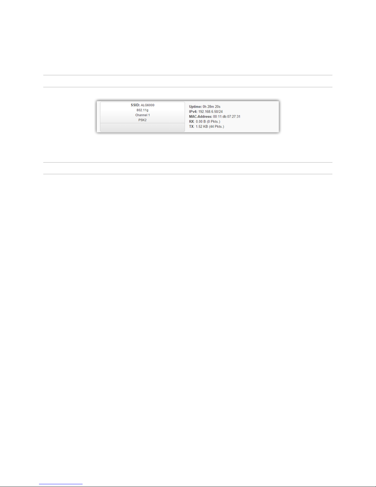
When access point mode is enabled, the ALG-6000 cellular router offers wireless tether. It forwards local
WiFi traffic to application servers over the cellular network and works in parallel with Ethernet connection,
providing for simultaneous WiFi and Ethernet connections.
5.5.1. Status
Figure 15. WLAN Status.
5.5.2. Access Point
ALG-6000 Series LTE Cellular Router | Page 26
Page 34
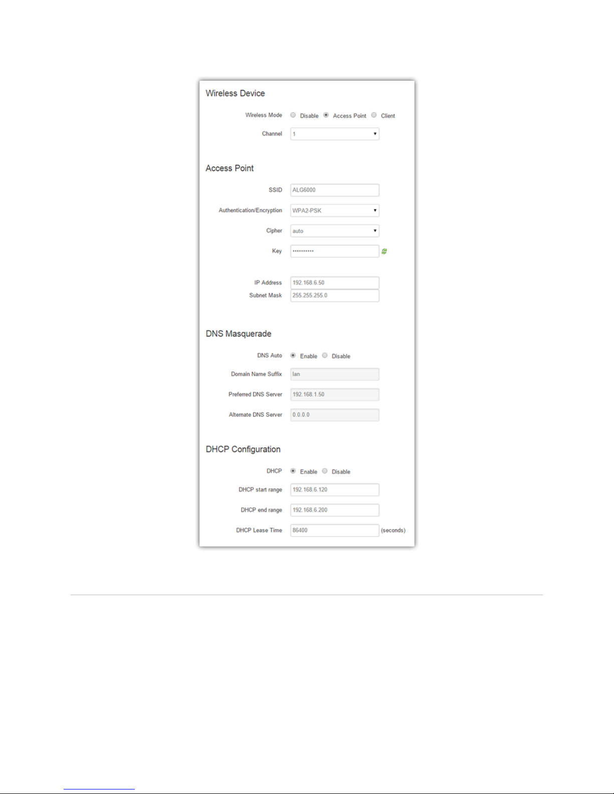
5.5.2.1. Wireless Device
Wireless Mode
o Disable – The WLAN interface is disabled.
o Access Point – The WLAN interface operates in Access Point mode. Parameters can be set
on the Access Point page.
o Client – The WLAN interface operates in Client mode. Parameters can be set on the Client
page.
Channel – Channel to be used in the Access Point mode.
Figure 16. Access Point Settings.
ALG-6000 Series LTE Cellular Router | Page 27
Page 35

5.5.2.2. Access Point
SSID – Name of the wireless local area network as broadcast to clients.
Authentication / Encryption – Type of authentication or encryption used. Extra fields may display
depending on the selected type.
Cipher – Cipher used with encryption selected above.
Key – Pre-shared key for authenticating clients
IP Address –IP Address of WLAN interface.
Subnet Mask – IP Subnet Mask assigned to the WLAN interface.
5.5.2.3. DNS Masquerade
DNS Auto – Selecting Enable will automatically set the preferred DNS Server to the WLAN IP
address of the router. Selecting Disable will require the user to specify the preferred and alternate
DNS servers.
Domain Name Suffice – DNS suffix assigned by the DHCP server.
Preferred DNS Server – IP address of primary DNS server.
Alternate DNS Server –IP address of secondary DNS server.
5.5.2.4. DHCP Configuration
DHCP – Selecting Enable will configure this device to assign IP addresses to client devices taken
from a pool specified by the values entered in DHCP start range and DHCP end range. Selecting
Disable will turn off the DHCP server functionality for the WLAN interface and require clients to
use statically configured IP addresses for network connectivity.
DHCP start range – Starting IP address from the DHCP server’s address pool.
DHCP end range – Ending IP address from the DHCP server’s address pool.
DHCP Lease Time – Duration in seconds that a client may be keep an assigned IP address before
requesting an address renewal.
5.5.3. Client
The user can configure up to 20 Access Points. The router will try to connect to the best Access Point in the
list that are reachable. When the router connects to an Access Point, it starts a DHCP client on the interface.
The Access Point must provide a DHCP server. The DHCP server must provide an IP address, network mask
and gateway to the ALG-6000 router. When the ALG-6000 is connected to an Access Point, the default
route is set to point to the gateway address obtained from the DHCP server.
Note: The Access Point must broadcast the SSID in order for the Client to be able to connect to it.
ALG-6000 Series LTE Cellular Router | Page 28
Page 36
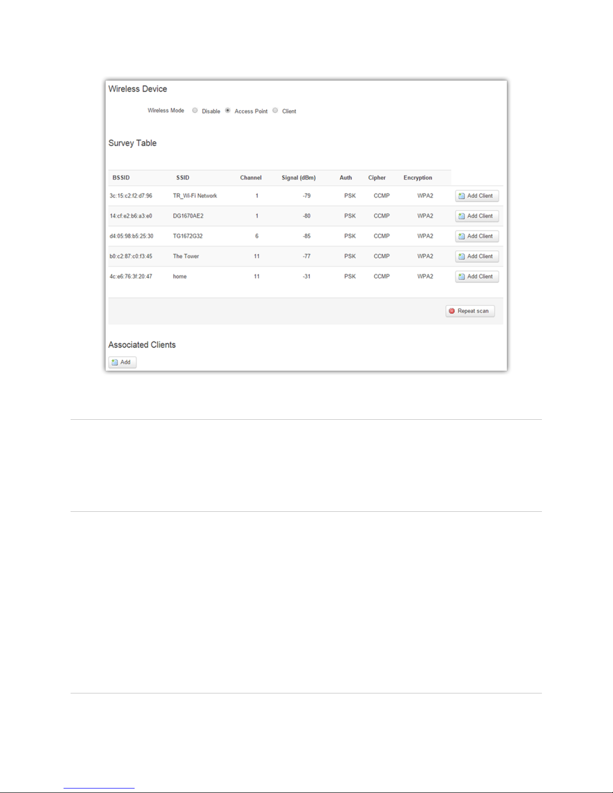
Figure 17. WLAN Client Settings.
5.5.3.1. Wireless Device
Wireless Mode – Selects the operation mode of the wireless network interface controller.
o Disable – Disables WLAN interface
o Access Point - Enables Access Point mode for using the ALG-6000 as a hotspot.
o Client – Enables Client mode for attaching the ALG-6000 as a client other WiFi hotspots.
5.5.3.2. Survey Table
When the WLAN interface of the ALG-6000 unit is configured for Client mode, this page scans for and
displays the WLAN Access Points that it detects. (This operation can take some time to complete.)
BSSID – Basic service set identifier (BSSID) – MAC address of access point.
SSID - Broadcasted SSID of the wireless network.
Channel - Specifies the wireless channel on which signal is found.
Signal - Signal strength of the network.
Auth - Type of Authentication used.
Cipher - Type of Cipher used for encryption.
Click Repeat Scan to force the router to scan for WLAN Access Points.
5.5.3.3. Associated Clients
ALG-6000 Series LTE Cellular Router | Page 29
Page 37
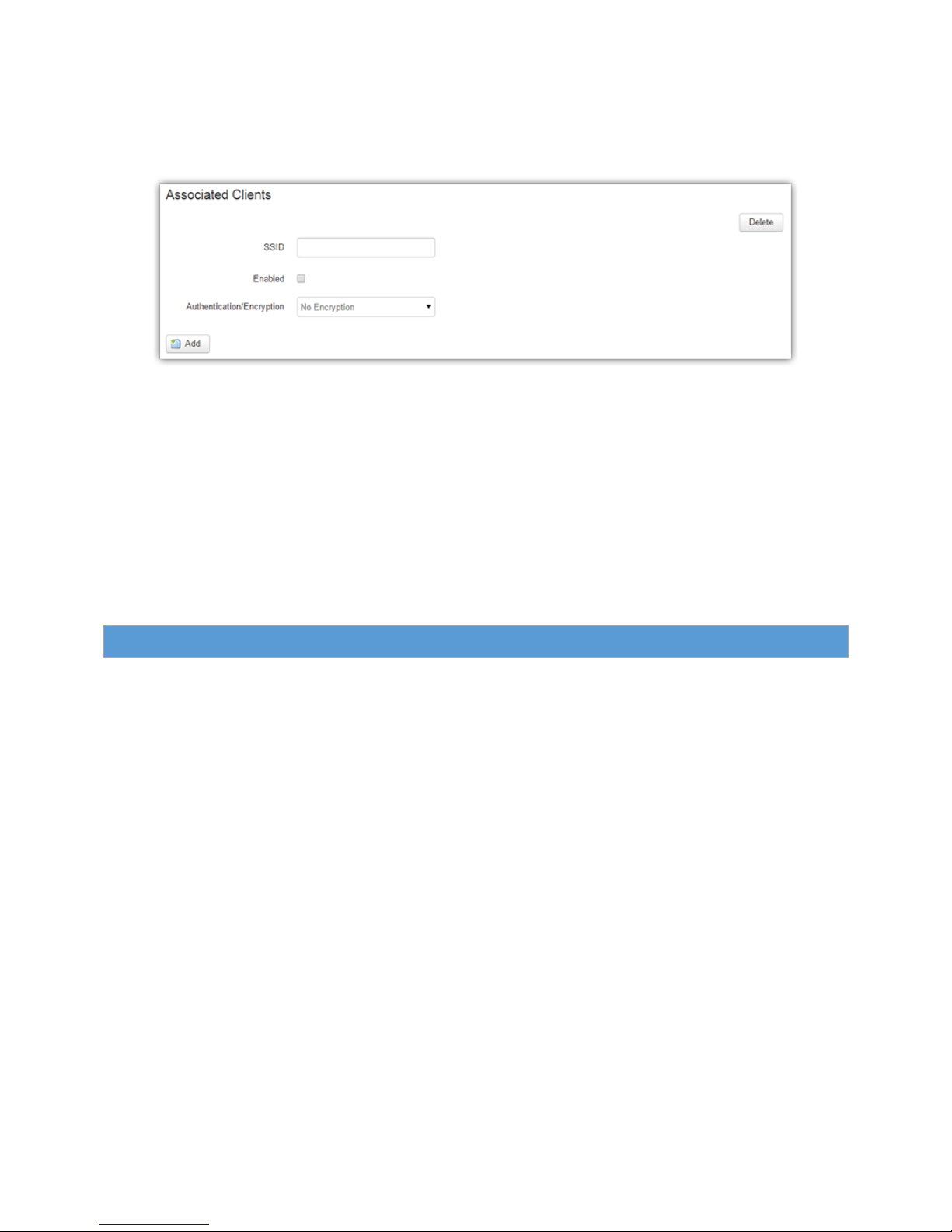
Click Add Client to manually add a WLAN Access Point. This may be used when adding networks not in
currently in range or not broadcasting their SSID.
Figure 18. Add Client section of WLAN Client page.
SSID – Name of wireless network to add.
Enabled – Select to enable automatic association with this network.
Authentication/Encryption – Wireless encryption method. Must match access point.
Cipher – Type of cipher(s) used for encryption. Default value: Auto
Key – Pre-shared key used with authentication/encryption and cipher above:
o WEP Cipher – 5 character ASCII string or 10 digit HEX string for 64 bit, 13 character ASCII
string or 26 digit HEX string for 128 bit
o TKIP Cipher – String of 8 to 63 alphanumeric characters
o AES Cipher – String of 8 to 63 alphanumeric characters
5.6. R ou te r
Select Router from the navigation menu to access the Port Forwards, IP Filtering, MAC Filtering , Static
Routing and ARP tabs.
ALG-6000 Series LTE Cellular Router | Page 30
Page 38
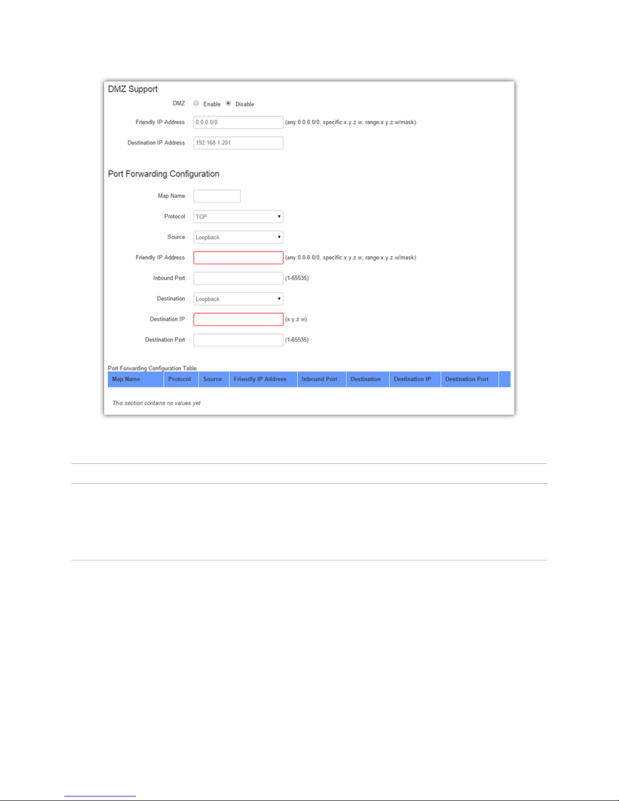
Figure 19. Port Forwarding under Router menu.
5.6.1. Port Forwards
Port Forwarding is a technique for transmitting and receiving network traffic through a router that involves
re-writing the source and/or destination IP addresses and usually the TCP/UDP port numbers of IP packets
as they pass through. The various routing configurations will be displayed in the IP mapping table at the
bottom of the Port Forwards page.
5.6.1.1. DMZ Support
DMZ is a host on the internal network that has all ports exposed, except those ports specified otherwise for
forwarding.
DMZ - Select Enable to allow the modem to use DMZ routes using the address set in the
Destination IP Address. Select Disable to shut down the DMZ functionality.
Friendly IP Address - Optionally restricts DMZ access to only the specified IP address. If set to
0.0.0.0 , the DMZ is open to all incoming IP Addresses.
Destination IP Address- The IP address which has all ports exposed, except ports defined in the Port
Forwarding configuration.
ALG-6000 Series LTE Cellular Router | Page 31
Page 39
5.6.1.2. Port Forwarding Configuration
Map Name - Sets the Map Name for the IP mapping table at the bottom of the page. The Map Name
can be up to ten characters in length. Do not use spaces in the character string.
Enabled - Port forwarding entries can be enabled or disabled individually.
Protocol - Sets the data protocol as either TCP, UDP or both.
Source - The Source interface is usually WAN.
Friendly IP Address - Specifies an IP address or subnet that is allowed to access the modem. Enter
0.0.0.0/0 to allow any address.
Inbound Port - Sets the external port number for incoming requests. (Note: Port Forwarding rules
take precedence over the services specified in LAN Settings » Remote Administration » Incoming
port, SSH Port, Telnet Port or SNMP Port.)
Destination - The Destination interface should correspond to the Destination IP Address.
Destination IP Address - Sets the Local Area Network Address of the device connected to the
modem's Ethernet jack. Inbound requests will be forwarded to this IP address.
Destination Port -Sets the Local Area Network port number used when forwarding to the
destination IP address.
5.6.2. IP Filtering
Figure 20. IP Filter settings under Router menu item.
ALG-6000 Series LTE Cellular Router | Page 32
Page 40

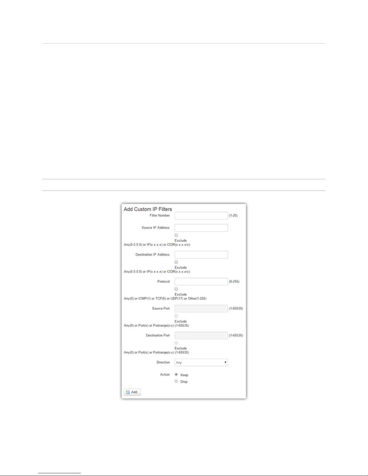
5.6.2.1. Add Custom IP Filters
You can define up to 20 IP filters. Each IP filter is identified by a unique number (from 1 to 20).
An IP packet goes through the filtering logic:
1) An IP packet is received on one of the interfaces and is destined to the ALG-6000 unit
OR
2) An IP packet is sent by the ALG-6000 unit
OR
3) An IP packet is forwarded by the ALG-6000 unit.
The filtering logic is the following :
if exists(filter[1]) AND match(packet, filter[1]) then apply(action[1])
else if exists(filter[2]) AND match(packet, filter[2]) then apply(action[2])
else if exists(filter[3]) AND match(packet, filter[3]) then apply(action[3])
else if exists(filter[20]) AND match(packet, filter[20]) then apply(action[20])
else process packet normally.
Where:
exists(filter[n]) -> The user as defined filter number n.
match(packet, filter[n]) -> The IP packet matches filter number n.
apply(action[n]) -> The action identified in filter number n.
Filter Number - Each IP filter is identified by a unique number from 1 to 20. Use Add to create new
rules; use Edit to update existing rules.
Source IP Address - The source IP Address or subnet that will satisfy this criteria. If the Exclude
field is checked, it means that in order for the packet to match with this criteria, it must NOT have
this source IP address (or NOT be in the given source IP address range).
Destination IP Address - The destination IP Address or subnet that will match. If the Exclude field is
checked, it means that for the packet to match this filter, it must NOT have this destination IP
address (or NOT be in the given destination IP address range).
Protocol -The protocol number that will satisfy this criteria. If the Exclude field is checked, it means
that for the packet to match this filter, it must NOT have this protocol number.
ALG-6000 Series LTE Cellular Router | Page 33
Page 41

Source Port - The source port number that will satisfy this criteria. This field is only enabled when
the Protocol is TCP(6) or UDP(17). If the Exclude field is checked, it means that for the packet to
match this filter, it must NOT have this source port number (or NOT be in the given source port
number range).
Destination Port - The destination port number that will satisfy this criteria. This field is only
enabled when the Protocol is TCP(6) or UDP(17). If the Exclude field is checked, it means that for
the packet to match this filter, it must NOT have this destination port number (or NOT be in the
given destination port number range).
Direction - The direction corresponds to the path taken by the IP packet inside the ALG-6000 unit.
An IP packet can TERMINATE inside the ALG-6000 unit.
WAN to ALG-6000: The IP packet is received from the WAN (cellular) interface and is destined to the
ALG-6000 unit.
LAN to ALG-6000: The IP packet is received from the LAN interface and is destined to the ALG-6000
unit.
WLAN to ALG-6000: The IP packet is received from the Wi-Fi interface and is destined to the ALG-6000
unit.
An IP packet can ORIGINATE from the ALG-6000 unit.
ALG-6000 to WAN: The IP packet is sent by the ALG-6000 unit to the WAN (cellular) interface.
ALG-6000 to LAN: The IP packet is sent by the ALG-6000 unit to the LAN interface.
ALG-6000 to WLAN: The IP packet is sent by the ALG-6000 unit to the ADD CUSTOM interface.
An IP packet can be FORWARDED by the ALG-6000 unit.
WAN to LAN: The IP packet is received on the WAN(cellular) interface and forwarded to the LAN
interface.
WAN to WLAN: The IP packet is received on the WAN(cellular) interface and forwarded to the ADD
CUSTOM
interface.
LAN to WAN: The IP packet is received on the LAN interface and forwarded to the WAN (cellular)
interface.
LAN to WLAN: The IP packet is received on the LAN interface and forwarded to the ADD CUSTOM
interface.
WLAN to LAN: The IP packet is received on the ADD CUSTOM interface and forwarded to the LAN
interface.
WLAN to WAN: The IP packet is received on the ADD CUSTOM interface and forwarded to the WAN
(cellular)
ALG-6000 Series LTE Cellular Router | Page 34
Page 42
interface.
If the Exclude field is checked, it means that for the packet to match this filter, it must NOT be processed in
the given
direction.
Action
o Keep : If IP filtering is enabled and an IP packet matches all criteria in the IP filter, keep the
IP packet (continue normal processing of the IP packet).
o Drop : If IP filtering is enabled and an IP packet matches all criteria in the IP filter, drop the
IP packet.
Custom IP Filters
Displays list of configured Custom IP filters.
Edit - Click Edit to edit the selected filter.
Delete - Click Delete to delete a filter.
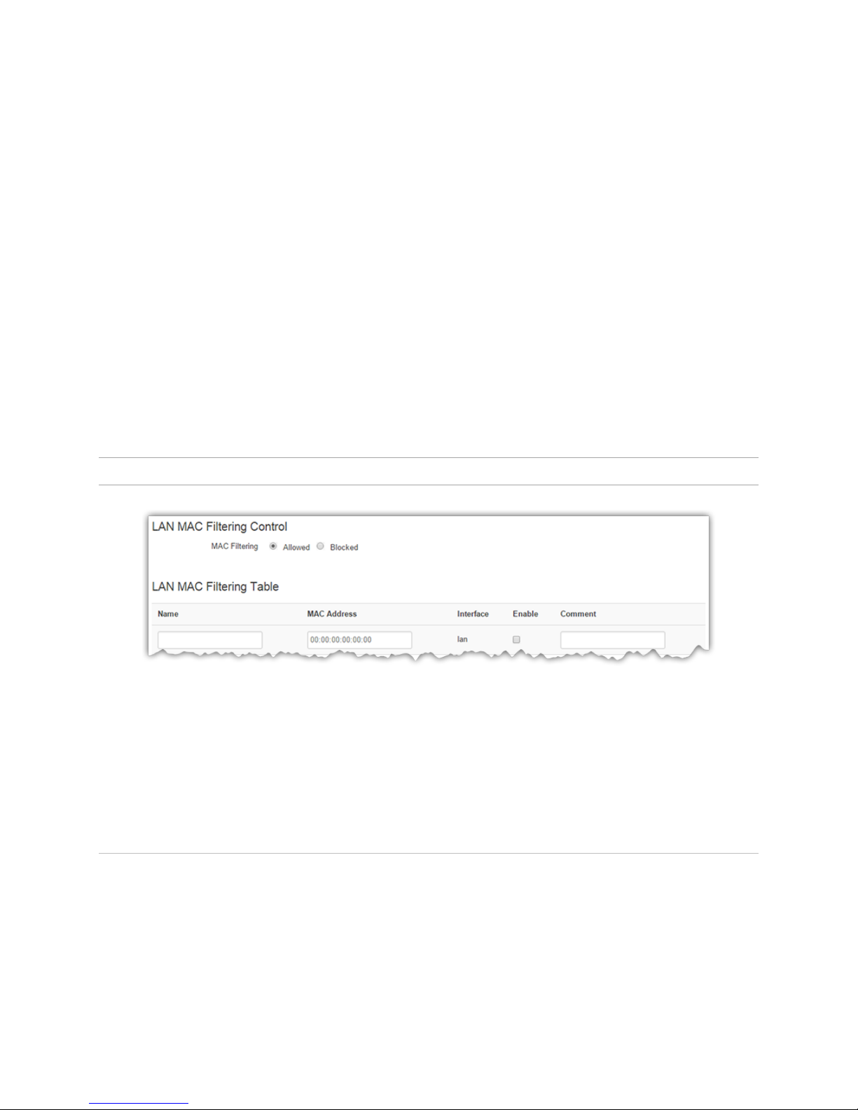
5.6.3. MAC Filtering
Figure 21. LAN MAC Filtering under Router menu item.
The MAC Filtering tab opens the MAC filtering configuration page. MAC filtering allows up to five device
MAC addresses to be entered for the LAN, and WLAN if installed, interfaces. The specific MAC addresses
can either be the only addresses allowed to access the device and network (whitelist) or can be blocked from
the device and network, allowing all other addresses through (blacklist).
5.6.3.1. LAN and WLAN MAC Filtering
ALG-6000 Series LTE Cellular Router | Page 35
Page 43
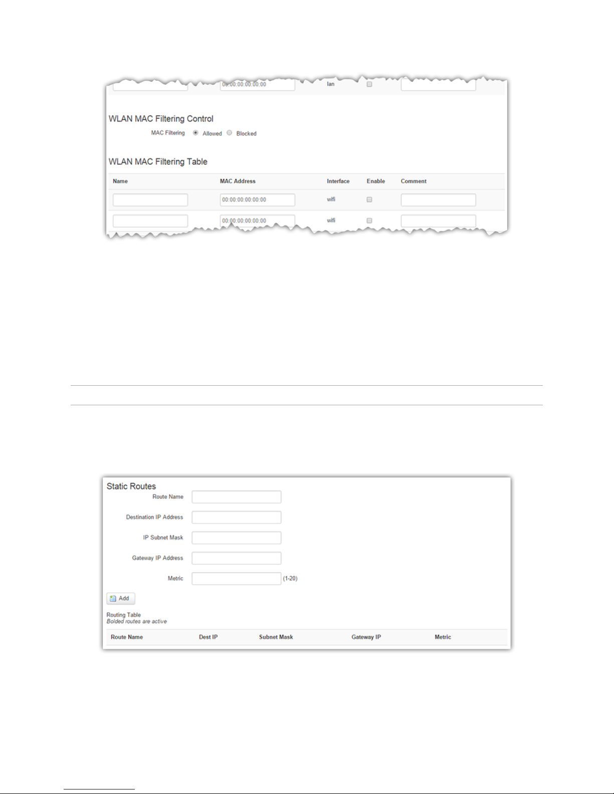
Figure 22. WLAN MAC Filtering under Router menu item.
MAC Filtering - Select Allowed or Blocked to define the type of filter configured.
Name - Name of the MAC filter rule.
MAC Address - Enter the MAC address for a device to be allowed or blocked on the network.
Comment - Enter an optional comment that describes the device at the allowed MAC address.
Enable - Check the box to activate the given filter.
5.6.4. Static Routes
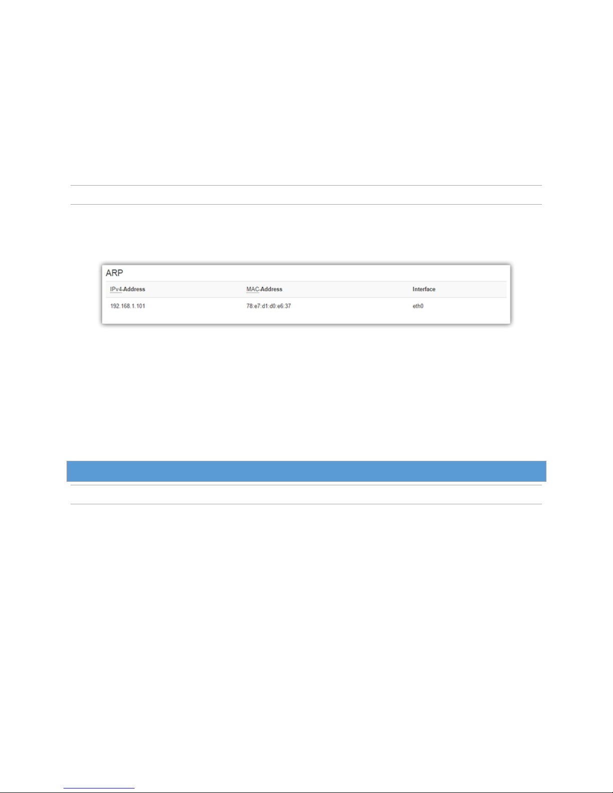
Select the Static Routes tab to open the routing configuration page. Static route tables may be created in
this page and appear at the bottom. Static Routing refers to a manual method used to set up routing
between networks.
Figure 23. Static Routes under Router menu item.
ALG-6000 Series LTE Cellular Router | Page 36
Page 44
Static Routes
Route Name - Sets the alphanumeric identifier of the static route in the Static Route table.
Destination IP Address -Sets the IP address of the destination network.
IP Subnet Mask - Sets the subnet mask of the destination network.
Gateway IP Address - This is only used if local IP address was selected for gateway. Enter the
address of the local gateway.
Metric - Enter a number from 1 to 20. The lower the metric value the higher the route priority.
5.6.5. ARP
Clicking Router > ARP displays the Address Resolution Protocol (ARP) table, which shows IP addresses, the
corresponding MAC address on the physical layer, and the interface known to the ALG-6000 router.
Figure 24. ARP (Address Resolution Protocol) under Router menu item.
IPv4-Address - IP Address of the device on one of the local interfaces (LAN or WLAN) with the
specified MAC Address.
MAC Address - The MAC Address of the locally connected device.
Interface - It is the interface name from which ARP request would have been sent by the router.
5.7. S ec ur ity
5.7.1. Status
ALG-6000 Series LTE Cellular Router | Page 37
Page 45
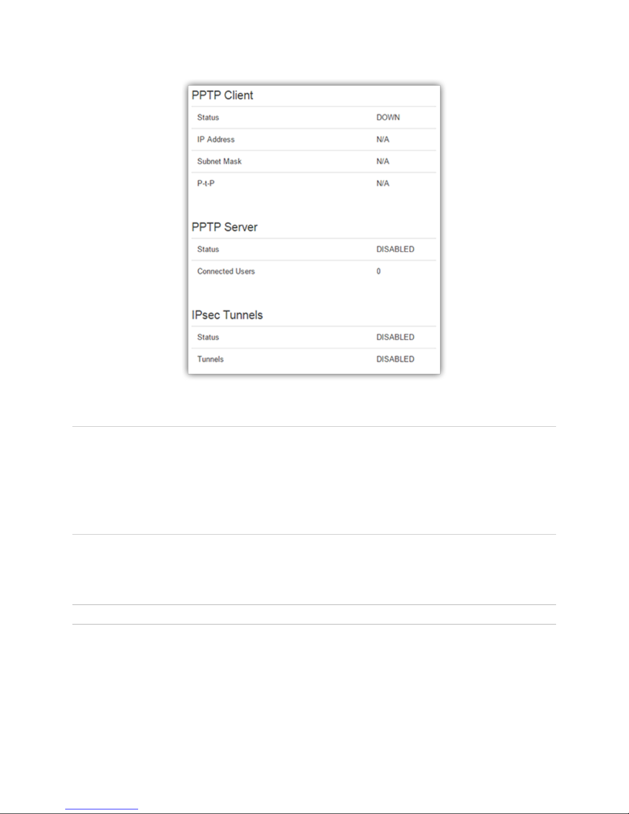
Figure 25. Security-Status
5.7.1.1. PPTP Client
Status - Indicates the status of the PPTP Client interface, usually UP when connected properly.
PPTP is the Point-to-Point Tunneling Protocol used to implement a Virtual Private Network (VPN).
IP Address - The current IP address assigned to the modem by the VPN server.
Subnet Mask - Usually set to 255.255.255.255, but may be different depending on VPN.
P-t-P - The PPTP P-t-P is the LAN address of your VPN server.
5.7.1.2. IPsec Tunnels
Status - The number of established IPsec tunnels based on the number of tunnels Enabled on the
Security | IPsec page.
5.7.2. PPTP
The Point-to-Point Tunneling Protocol (PPTP) is a method for implementing virtual private networks (VPN).
ALG-6000 Series LTE Cellular Router | Page 38
Page 46
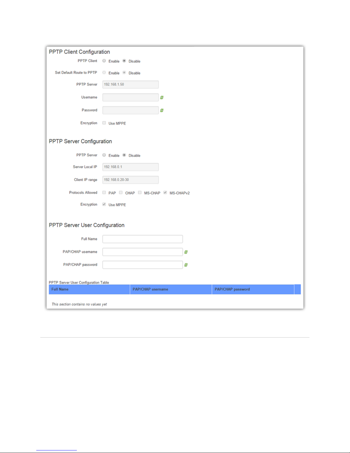
5.7.2.1. PPTP Client Configuration
PPTP Client - Selecting Enable will allow the PPTP functionality. Selecting Disable will shut off
PPTP functionality.
Set Default Route to PPTP - Selecting Enable will route all IP traffic through the PPTP network.
Selecting Disable will route only PPTP traffic through the PPTP network.
PPTP Server - The IP address of the virtual private network server on which to connect.
Username - The username required by the VPN server.
Password - The password, associated with the username, required by the VPN server.
Figure 26. Security PPTP
ALG-6000 Series LTE Cellular Router | Page 39
Page 47

Encryption - Selecting Use MPPE will enable Microsoft Point-to-Point Encryption for
communication between the server and clients. This option requires the MS-CHAP or MS-CHAPv2
protocol.
5.7.2.2. PTPP Server Configuration
PPTP Server - Selecting Enable starts the VPN server, and selecting Disable stops it.
Server Local IP - The IP address that clients will use to communicate with the server after they
connect.
Client IP Range - The pool of IP addresses assigned to clients.
Protocols Allowed - Selecting a protocol will instruct the VPN server to accept clients who use that
protocol. The server will reject clients using any of the un-selected protocols.
Encryption - Selecting Use MPPE will enable Microsoft Point-to-Point Encryption for
communication between the server and clients. This option requires the MS-CHAP or MS-CHAPv2
protocol.
5.7.2.3. PPTP Server User Configuration
Full Name - This name can be used as a more descriptive name for a client. It is not used by the
server. No spaces are allowed in the name.
PAP/CHAP Username - The name used by a client to log in to the server.
PAP/CHAP Password - The password, with associated username, used by a client to log in to the
server.
5.7.2.4. PPTP Server User Configuration Table
Displays list of user- configured PPTP servers user credentials.
o Edit - Click Edit to edit the selected filter.
o Delete - Click Delete to delete a filter.
5.7.3. IPSEC
IPsec serves to configure secured communication tunnels. The various tunnel configurations will be
displayed in the Tunnel Configuration Table. All tunnels are created using the ESP (Encapsulating Security
Payload) protocol.
ALG-6000 Series LTE Cellular Router | Page 40
Page 48
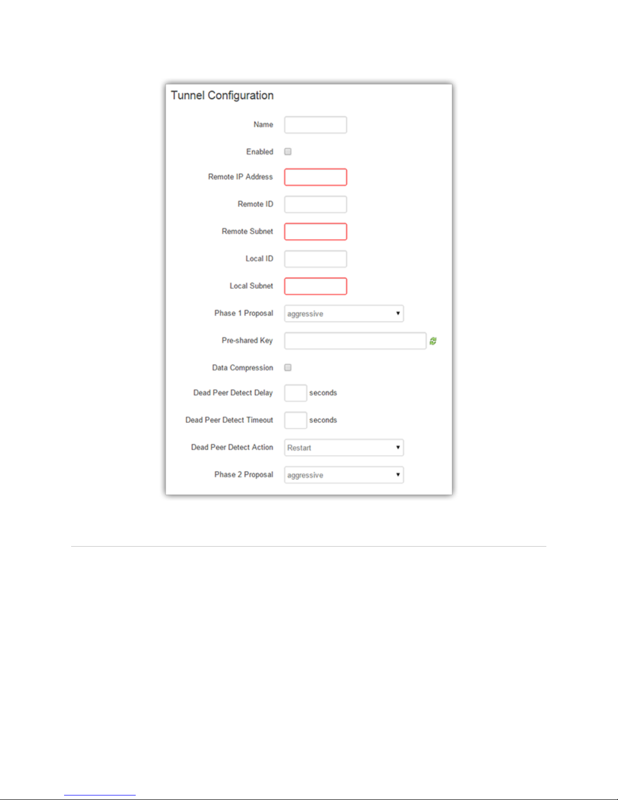
5.7.3.1. Tunnel Configuration
Name - A name for the IPsec tunnel. Once a tunnel is defined, it can be enabled by checking the
Enable box. To edit an existing tunnel (these are displayed in the Tunnel Configuration Table), click
the Edit button to the right of the table entry and the saved values are displayed for editing.
Enabled - Check Enable to enable a tunnel.
Remote IP Address - The public IP address of the remote IPsec server or the firewall in front of the
IPsec server.
Remote ID - The IP address of the remote IPsec server. Usually empty if the IPsec server is not
behind a firewall.
Remote Subnet - Enter an IP address/mask if encrypted packets are also destined for the specified
network that is beyond the Remote IP Address.
o IMPORTANT: The Remote Subnet and Local Subnet addresses must not overlap!
Figure 27. Security - IPsec
ALG-6000 Series LTE Cellular Router | Page 41
Page 49

Local Subnet - Enter an IP address/mask of the local LAN whose are packets are to be encrypted
and sent over the tunnel. (LAN Settings » Bind to Eth IP may need to be enabled to make sure that
packets generated by ALG-6000 services appear to originate from the local LAN address.).
o IMPORTANT: The Remote Subnet and Local Subnet addresses must not overlap!
Phase 1 Proposal - Select an entry from the Proposal table.
Pre-shared Key - Predetermined key known to both the local unit and the remote side prior to
establishing the tunnel.
Perfect Forward Secrecy - Enable Perfect Forward Secrecy for the session keys. Without Perfect
Forward Secrecy, new encryption keys are derived from the expiring encryption key
algorithmically; Perfect Forward Secrecy generates the new key from scratch.
Dead Peer Detect Delay - Tunnel keep alive time for R_U_THERE packets during idle periods.
Dead Peer Detect Timeout - Timeout time during tunnel idle periods where no R_U_THERE_ACK
has been received.
Dead Peer Detection Action - Action to be taken when timeout value is reached.
Phase 2 Proposal - Select an entry from the Proposal table.
5.7.3.2. Tunnel Table
Edit - Click the Edit button to edit the properties of a tunnel.
Delete - Click the Delete button to delete the tunnel.
5.7.3.3. Proposals
The Phase 1 and Phase 2 Encryption, Authentication, DH Group and Life Time parameters can be changed
from this section. The Delete button is displayed only for proposals that are not referenced by any Tunnel
configurations.
5.7.4. GRE
The GRE page is used to add and delete GRE (Generic Route Encapsulation) tunnels. Current tunnels are
listed below. Up to two networks that lie beyond the tunnel may be specified and routes to those networks
are automatically created when the tunnel is established. Static local and remote IP addresses are necessary
to allow for the tunnel automatic (re)connection.
Note:
All subnets must differ from one another and must not overlap.
If more than two remote user subnets are necessary, additional routes can be setup manually via
the Router »Static Routes tab using the Tunnel IP Address as the gateway.
ALG-6000 Series LTE Cellular Router | Page 42
Page 50
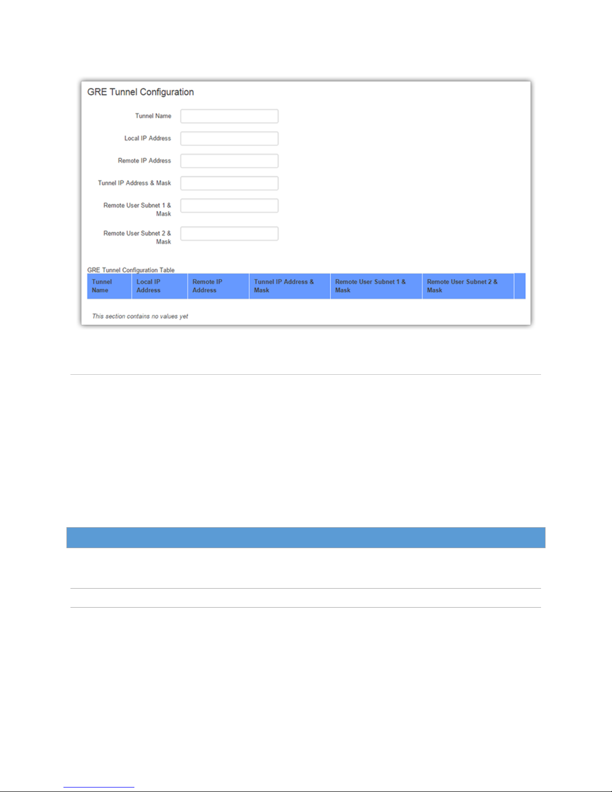
Figure 28. Security - GRE
5.7.4.1. GRE Tunnel Configuration
Tunnel Name - The name associated with the tunnel.
Local IP Address - The local (normally WAN interface) IP address associated with the tunnel.
Remote IP Address - The remote IP address associated with the tunnel.
Tunnel IP Address & Mask - The IP address assigned to the tunnel interface. [ Example:
192.168.10.100 ]
Remote User Subnet 1 & Mask - The IP network representing that of the remote user subnet,
accessible via the tunnel. [ Example: 192.168.20.0/24 ]
Remote User Subnet 2 & Mask - A possible second IP network representing another remote user
subnet. [ Example: 192.168.15.0/24 ]
5.8. S er ia l
From the main navigation pane, select Serial for access to the external serial port configuration page.
5.8.1. External Serial
Use the External Serial tab to define and configure the functioning of the RS-232 Serial Port, which can be
set to output GPS position reports or to function as a Packet Assembler and Disassembler (PAD),
transferring all serial data to or from a specified TCP port.
ALG-6000 Series LTE Cellular Router | Page 43
Page 51
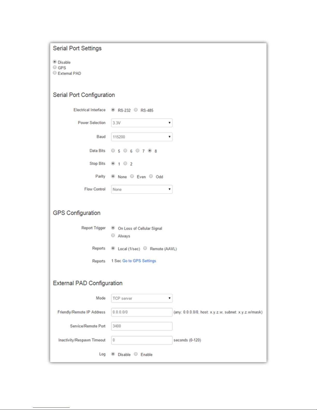
ALG-6000 Series LTE Cellular Router | Page 44
Page 52

Figure 29. Serial - External Serial
5.8.1.1. Serial Port Settings
Disable - The serial port is not assigned GPS or PAD functionality. When Disabled, the port is free
for use.
GPS - The serial port will stream the configured GPS sentences at a selected rate, as setup from the
GPS page.
External Pad - The serial port will be bridged to the configured TCP port, providing access to serial
devices over the WAN.
5.8.1.2. Serial Port Configuration
Electrical Interface - Sets the serial port to use either RS-232 or RS-485. RS-485 is a balanced
electrical interface suited for multidrop applications, such as communication over long cable
distances or in noisy environments. When RS-485 is selected, the Flow Control option becomes
unavailable.
Power Selection - Select voltage present on pin 9 of the COM 1 DB-9 serial connector. This voltage
can be used to power any serial adapter connector to COM 1.
Baud - Select the serial port baud.
Data Bits - Select the number of data bits per character: 5, 6, 7, or 8.
Stop Bits - Select the number of stop bits per character: 1 or 2.
Parity - Select the type of parity per character: None, Even or Odd.
Flow Control - Select the type of flow control: None, or Hardware (RTS/CTS).
5.8.1.3. GPS Configuration
Select GPS to enable GPS reports through the serial port. Note that the report format is set in the GPS >
Settings tab. Set the appropriate TCP Server Format in the Local and/or Remote Delivery sections.
Report Trigger
o On Loss of Cellular Signal: Select this if the GPS reports are output only when the cellular
signal is lost. Note that there can be a delay of around 30 seconds before the serial reports
appear on the serial port after the cellular signal is lost.
o Always: GPS reports are always sent out the serial port.
Reports
o Local (1/sec): Select this to have the Local report sent out the serial port each second.
o Remote (AAVL): Select this to have the Remote report sent out the serial port. The report
rate is based on the AAVL settings.
5.8.1.4. External Pad Settings
The PAD Server mode configures the service to accept one incoming TCP connection on the specified port.
The modem will not accept multiple incoming connections at the same time.
TCP Port -The port number exposed to the WAN/LAN interfaces as the serial PAD service.
State -Select the PAD operating state: raw to transfer data as-is, telnet when the connecting device
uses the telnet protocol.
ALG-6000 Series LTE Cellular Router | Page 45
Page 53

Inactivity Timeout - Time after which the current connection with Client will be terminated without
warning. This time starts over again each time the Client sends data to the server. The timeout is
between 1-120 seconds. Enter 0 for no timeout.
Log - When enabled, as data passes through the PAD, a copy is stored in an internal log file. Contact
Technical Support for assistance on retrieving the log.
Friendly IP Address - Sets the IP address of the client that is allowed to connect to the PAD service.
5.9. G PS /GNSS
The ALG-6000 contains a standalone, high-accuracy, high-report-rate GPS receiver.
The GPS LED on the front panel provides the status of the receiver.
5.9.1. Status
This section displays the current status of the GPS receiver.
5.9.1.1. Status
Condition - Indicates the quality of received GPS reports.
Number of Satellites - Indicates the number of satellite signals being received and used to calculate
position.
UTC - The current time according to Universal Coordinated Time in hh:mm:ss, using a 24-hour clock
format.
Position - The current position in Latitude (North-South) and Longitude (East-West Positions are
reported in degrees, minutes and seconds. For example, a Longitude of 73 degrees, 39 minutes and
45 seconds West appears as: 73 39’ 45” W.
Altitude - The current height above Mean Sea Level in meters.
True Course - Shows the current GPS-generated true course in degrees.
Ground Speed - Shows travel speed (in Km/h).
Figure 30. GPS/GNSS - Status
ALG-6000 Series LTE Cellular Router | Page 46
Page 54
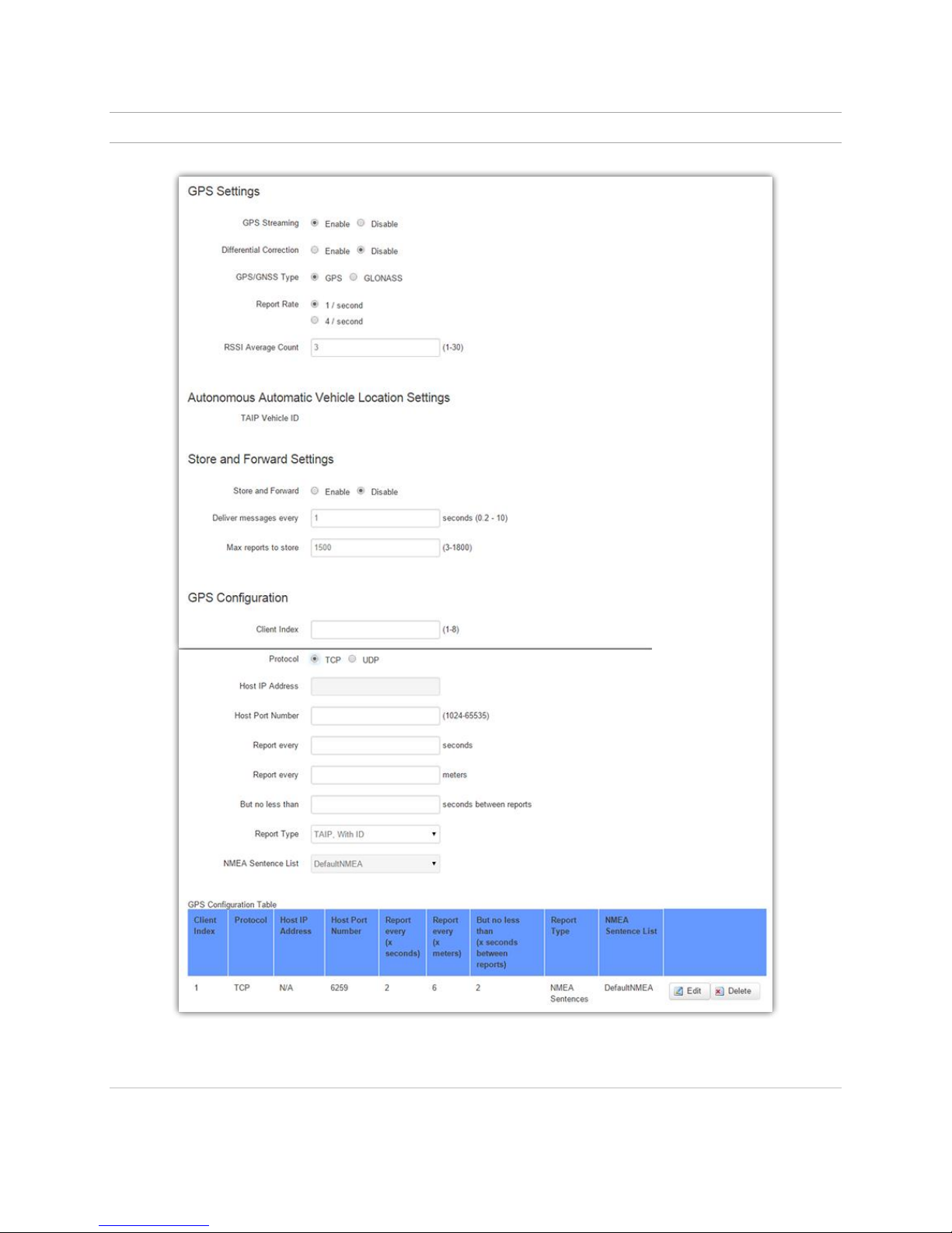
5.9.2. Settings
5.9.2.1. GPS Settings
Figure 31. GPS - Settings
ALG-6000 Series LTE Cellular Router | Page 47
Page 55

GPS Streaming - Select Enable to start the GPS engine, Disable to stop it
Differential Correction - Differential Correction allows WAAS correction information to be used to
improve accuracy of the GPS position reports.
o Note: WAAS correction applies to North America only. The WAAS satellites currently in
service are 48 (Galaxy 15) and 51 (Anik F1R). The previous WAAS satellites 35 and 47 were
taken out of service on 2007/07/30.
GPS/GNSS Type - Select GPS or GLONASS.
Report Rate - For applications that require it, GPS reports are normally received from the internal
GPS receiver at a rate of once per second. Local Delivery reports are sent at this rate. Remote
Delivery reports are limited by the “But no less than X seconds between reports” setting.
RSSI Average Count (1-30) - This value is used for averaging the satellite signal strength.
5.9.2.2. Autonomous Automatic Vehicle Location (AAVL) Settings
The Autonomous Automatic Vehicle Location (AAVL) feature adds the ability for GPS-equipped ALG-6000
Cellular Broadband Routers to transmit position reports either to a host connected to the local Ethernet
port or to a remote host over the cellular network. AAVL allows the system designer to specify the
maximum distance or the time interval between remote position reports. Position reports can be
transmitted in a number of possible formats. When the format is disabled or the Address or Port fields are
blank, no report is sent.
GPS “sentences” are collected the from embedded GPS receiver in the ALG-6000 Cellular Broadband
Router. These sentences are converted into the above formats and are provided to both local and remote
delivery services. Each report from the TCP ports is terminated with carriage-return/linefeed characters
(CRLF). Up to two local UDP Hosts and three remote UDP Hosts may be specified. Reports are sent as a
datagram with no terminating CRLF.
TAIP Vehicle ID - The TAIP, With ID format allows a report to contain a user-supplied field to
identify the sending mobile. This read-only field, which may contain up to 8 letters or digits (special
characters not allowed), is taken from the Unit ID that can be set from Unit Status » Basic Settings »
Unit ID » ID.
5.9.2.3. Store and Forward Settings
The ALG-6000 router can be configured to store reports generated by the Remote Delivery configuration
when out of coverage. Those reports will be forwarded to the specified host(s) when the router
reestablishes its cellular connection.
Store and Forward - Enable or disable the Store and Forward feature of the ALG-6000.
Deliver messages every ( ) seconds - This specifies the rate used to deliver the stored messages to
the host(s) when the unit is again within coverage. This MUST be configured faster than the reports
being generated by the Remote Delivery configuration.
Max reports to store - This specifies the maximum number of reports to store. When filled, the
oldest reports will be overwritten by new reports. (This maximum is divided by the number of
different formats that have to be stored and forwarded. For example, if remote hosts only receive
the GGA message, then up to 1800 reports can be stored; if remote hosts are to receive GGA and
RMC messages, then up to only 900 pairs can be stored.)
5.9.2.4. GPS Configuration
ALG-6000 Series LTE Cellular Router | Page 48
Page 56

Client Index (1-8) - Specify an index number(1-8) of the client, to be used for keeping track of the
delivery table entries.
Protocol - Select TCP for connection-oriented or UDP for connectionless datagrams.
Host IP Address - Specify the IP address for this GPS client, to allow destination for UDP. This field
is valid only if protocol is UDP.
Host Port Number (1024-65535) - Specify the port for this GPS client.
Report every ( ) seconds - Triggers the sending of a new remote report if the time since the last
remote report exceeds the specified number of seconds.
Report every ( ) meters - Triggers the sending of a new remote report if the distance since the last
remote report exceeds the specified distance (in meters).
But no less than ( ) seconds between reports - To prevent a fast-moving vehicle from reporting too
frequently, a lower limit on the time between reports can be specified.
Report Type - Specify the type of reports. Client can select the following report types:
TAIP, no ID
Selecting TAIP, no ID as report type client will get TAIP messages.
Example:>RPV73511+4549542-0736643100035822;*7F<
TAIP, with ID
It is similar to above report type, but Along with this client will get Vehicle ID in Reports.
Example:>RPV56655+4549542-0736643300000002;ID=ADAM12;*5E<
NMEA Sentences
Selecting NMEA Sentences as report type, client will get NMEA Sentence in reports.
Example: $GPGGA,202742.0,4529.7240,N,7339.8585,W,2,9,0.9,28,M,,,,*3E
$GPGLL,4529.7241,N,7339.8584,W,202645.0,A,D*7C
$GPRMC,153716.00,A,4529.72428,N,07339.86082,W,0.007,,180108,,,A*69
$GPVTG,,T,,M,0.004,N,0.008,K,A*2F
NMEA Sentence List - Select the NMEA Sentence List. Client can create a new NMEA Sentence list.
GNSS sentences are collected the from the internal GNSS receiver in the router. These sentences are
converted into the above formats and are provided to both local and remote delivery services. Two TCP
ports are available for clients to connect to and receive reports at the local or remote reporting rate. Each
report from the TCP ports is terminated with carriage-return/linefeed characters (CRLF). Up to two local
UDP Hosts and three remote UDP Hosts may be specified. Reports are sent as a datagram with no
terminating CRLF.
5.9.2.5. GPS Configuration Table
This section displays information for all clients present.
ALG-6000 Series LTE Cellular Router | Page 49
Page 57

Edit - Click the Edit button to modify the existing settings for any client.
5.9.2.6. NMEA Sentences
This section displays all NMEA Sentence Lists currently present.
Add - You can add a new NMEA Sentence List by entering a unique name, and then clicking the Add
button.
5.10. Diagn os tic s
From the main navigation pane, select Diagnostics for access to the SNMP, and Logging configuration pages.
5.10.1. SMS
The SMS CLI (Command-Line Interface) allows a small set of commands to be sent to the ALG-6000 using
SMS.
ALG-6000 Series LTE Cellular Router | Page 50
Page 58
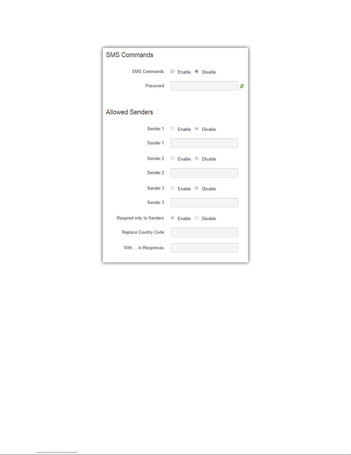
Figure 32. Diagnostics - SMS
All commands are prefixed with the slash “/” character. Note that […] denotes an optional field. The
supported commands are:
/status [pw=password]
Returns the following fields:
WAN= DOWN or the IP address of the cellular connection
RSSI= the signal strength of the cellular radio channel
ECIO= the interference on the cellular radio channel
PPTP= the state of the PPTP VPN: UP or DOWN
IPSEC= the number of active / enabled / defined tunnels
ALG-6000 Series LTE Cellular Router | Page 51
Page 59

GPS= the latitude, longitude (in decimal degrees) of the modem
V= the main voltage of the modem
T= the temperature of the modem
D1=, D2= the state of the twor digital inputs: 0 (inactive) or 1 (active)
A1=, A2= the levels of the two analog inputs, in volts
/pptpstart [pw=password]
Starts the PPTP VPN.
/pptpstop [pw=password]
Stops the PPTP VPN.
/ipsecstart [pw=password] tun=label
Starts the IPsec tunnel that has the specified label .
/ipsecstop [pw=password] tun=label
Stops the IPsec tunnel that has the specified label .
5.10.1.1. SMS Commands
SMS Commands
o Enable allows the ALG-6000 to respond to received SMS commands.
o Disable causes SMS messages (that start with a slash) to be accepted but quietly discarded.
Password
o If nonblank, all commands require the password in the form pw=password as one of the
arguments. The pw prefix can occur in any case (“pw=”, “PW=”, “Pw=”, etc.) but the
password must be in the exact case as entered on the web page.
5.10.1.2. Allowed Senders
Sender 1 / Sender 2 / Sender 3 - Commands can be restricted to be accepted only if they arrive from
one of up to three “friendly” SMS Sender addresses, which can enabled or disabled as necessary.
Sender addresses are typically numeric digits only including the country code prefix. Select the
button for a Sender (1-3), and then enter the address in the adjacent field. If all three addresses are
disabled, then commands will be accepted from ALL senders.
Respond only to Senders - For security, command responses, including error messages, can be
restricted to be returned only to the registered Sender SMS addresses.
Replace Country Code - This allows you to change the country that the responder uses, which can
be useful when monitoring routers across national borders.
With … in responses - The string you wish to substitute for the country code.
ALG-6000 Series LTE Cellular Router | Page 52
Page 60
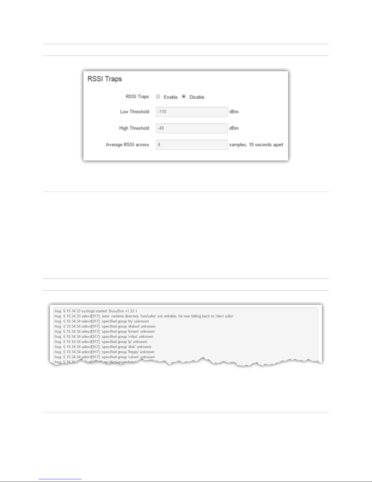
5.10.2. RSSI Traps
5.10.2.1. RSSI Traps
Figure 33. Diagnostics - RSSI Traps
Generate SNMP traps and notifications when the cellular signal strength (RSSI) falls outside of specified
thresholds
RSSI Traps - Selecting Enable allows the monitoring of the cellular signal strength.
Low Threshold - Send an SNMP Trap message when the average RSSI falls below this value.
High Threshold - Send an SNMP Notification message when the average RSSI rises above this value.
Average RSSI Across - The number of samples, taken 10 seconds apart, used to compute the
average RSSI.
5.10.3. Syslog Settings
Figure 34. Diagnostics - Syslog Settings
5.10.3.1. Syslog Configuration
UDP Log Server IP Address - IP address of the server to which the logs will be routed.
ALG-6000 Series LTE Cellular Router | Page 53
Page 61
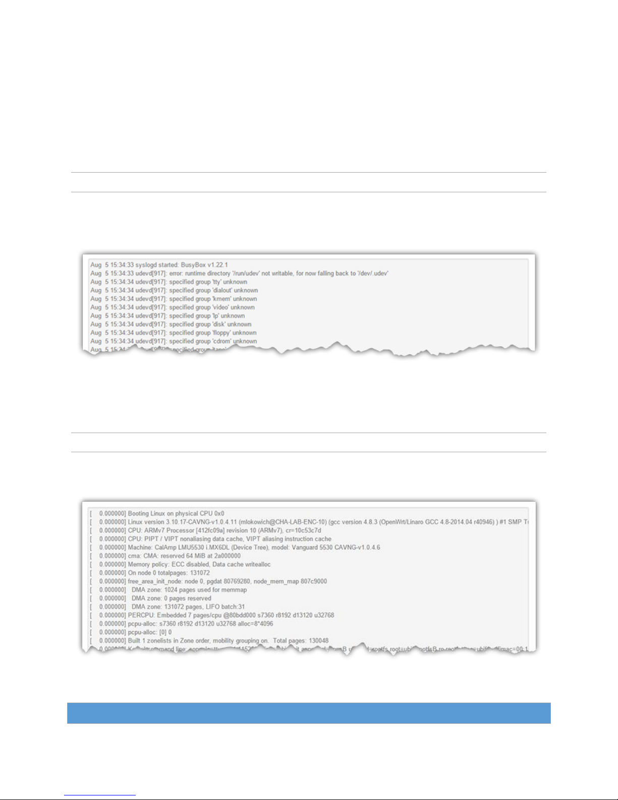
UDP Log Server Port - Port number of the Log Server.
Log Size - Maximum size in bytes that the log is allowed to reach before it is archived and a new log
is started.
Log Rotation Count - Number of archived files to keep. Oldest file is abandoned when the rotation
count is exceeded.
Log Priority - Define the depth of the information logged by the system logger facility. The higher
the priority is, the deeper the information.
5.10.4. System Log
The System Log page provides a way to capture the current status log of the modem. Log information is
useful when contacting Atlas Labs Technical Support to resolve operational problems.
Figure 35. Diagnostics - System Log
5.10.5. Kernel Log
The Kernel Log page provides a way to capture the kernel log of the modem.
5.11. I/O S et tin gs
Figure 36. Diagnostics - Kernel Log
ALG-6000 Series LTE Cellular Router | Page 54
Page 62
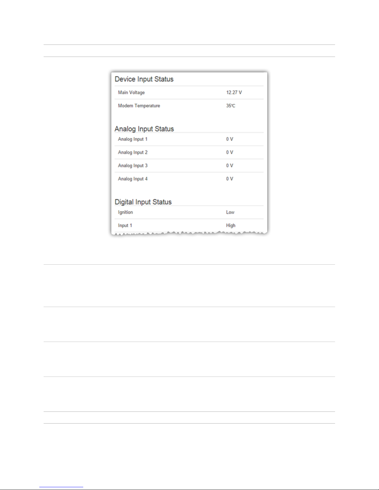
5.11.1. Status
Figure 37. I/O Settings
5.11.1.1. Device Input Status
Main Voltage - Displays current voltage applied to the unit, in Volts.
Modem Temperature - Displays temperature of the Wireless Modem, in Celsius.
5.11.1.2. Analog Input Status
Analog Input 1-4 - Displays voltage of the specified analog input, in Volts.
5.11.1.3. Digital Input Status
Ignition and Input 1-7 - Displays the status of the specified input: Active (high state) or Normal (low state).
5.11.1.4. Digital Output Status
Output 1-7 - Displays if the specified output is open or ground.
5.11.2. SNMP
ALG-6000 Series LTE Cellular Router | Page 55
Page 63
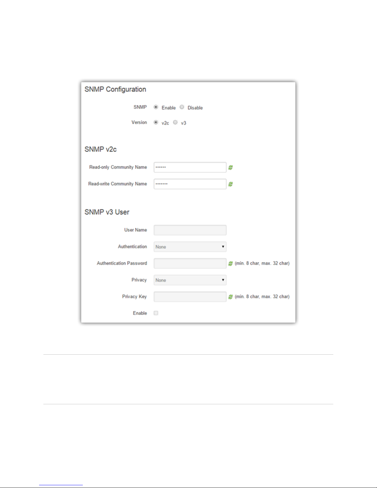
The Simple Network Management Protocol (SNMP) is used in network management systems to monitor
network attached devices for conditions that warrant administrative attention. SNMP version v2c and v3
are supported with the exception of INFORM.
5.11.2.1. SNMP Configuration
SNMP - Selecting Enable will allow the SNMP functionality. Selecting Disable will shut off SNMP
functionality.
Version - With SNMP Enabled, select the corresponding version that matches the SNMP Manager.
5.11.2.2. SNMP v2c
Read-only Community Name - The community string used for accessing the read-only Management
Information Bases (MIBs).
Figure 38. I/O Settings - SNMP
ALG-6000 Series LTE Cellular Router | Page 56
Page 64
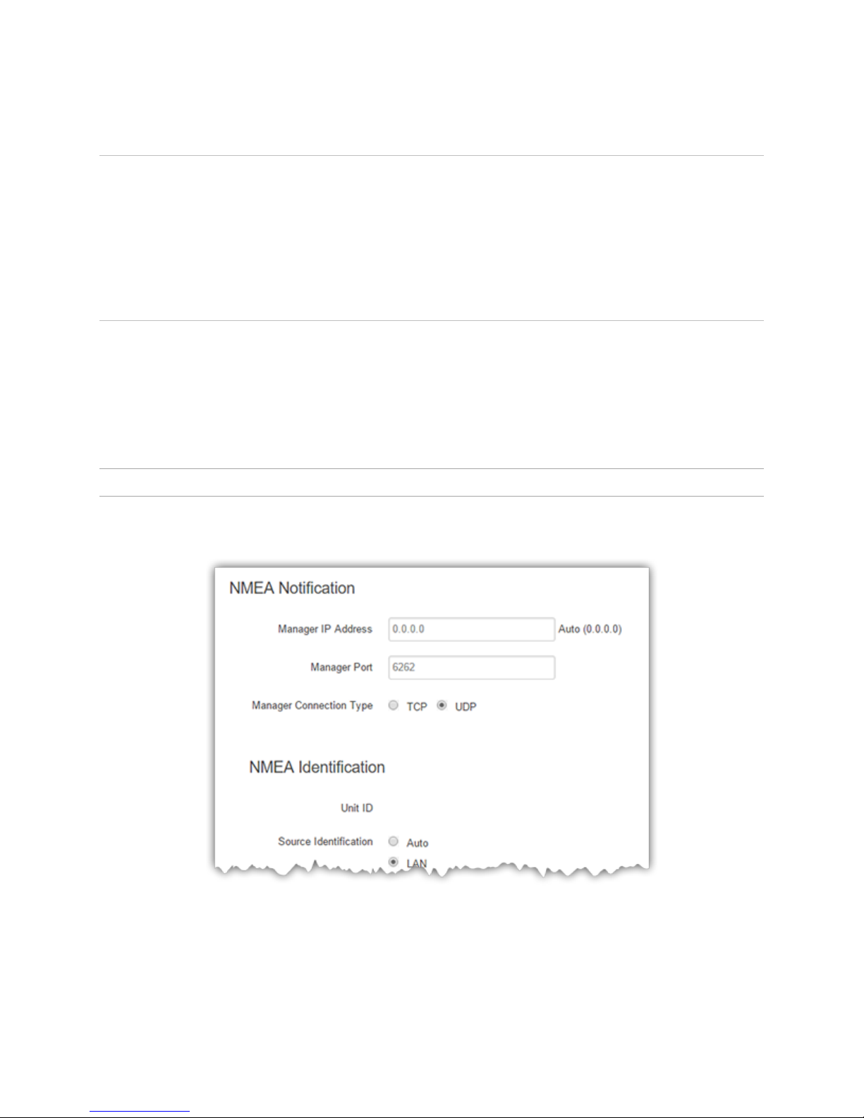
Read-write Community Name - The community string used for accessing all Management
Information Bases (MIBs) including writable objects.
5.11.2.3. SNMP v3
User Name - The user name for secure access to the Management Information Bases (MIBs)
observing v3 standard.
Password - The corresponding user password for accessing the Management Information Bases
(MIBs) including writable objects.
Authentication - Selecting the authentication method for accessing the Management Information
Bases (MIBs).
5.11.2.4. Traps
Server Name - Name of server to which the trap events will be sent.
Enabled - Selecting Enable will allow the active trap events to be reported to the defined server(s).
Selecting Disable will deactivate events reporting. Up to four destinations can be specified.
Server Address - IP address of server to which the trap events will be sent.
Server Port - The corresponding server port to which the trap events will be sent (default 162).
5.11.3. Settings
This section is reserved for future use.
Figure 39. I/O Settings - reserved for future use.
ALG-6000 Series LTE Cellular Router | Page 57
Page 65
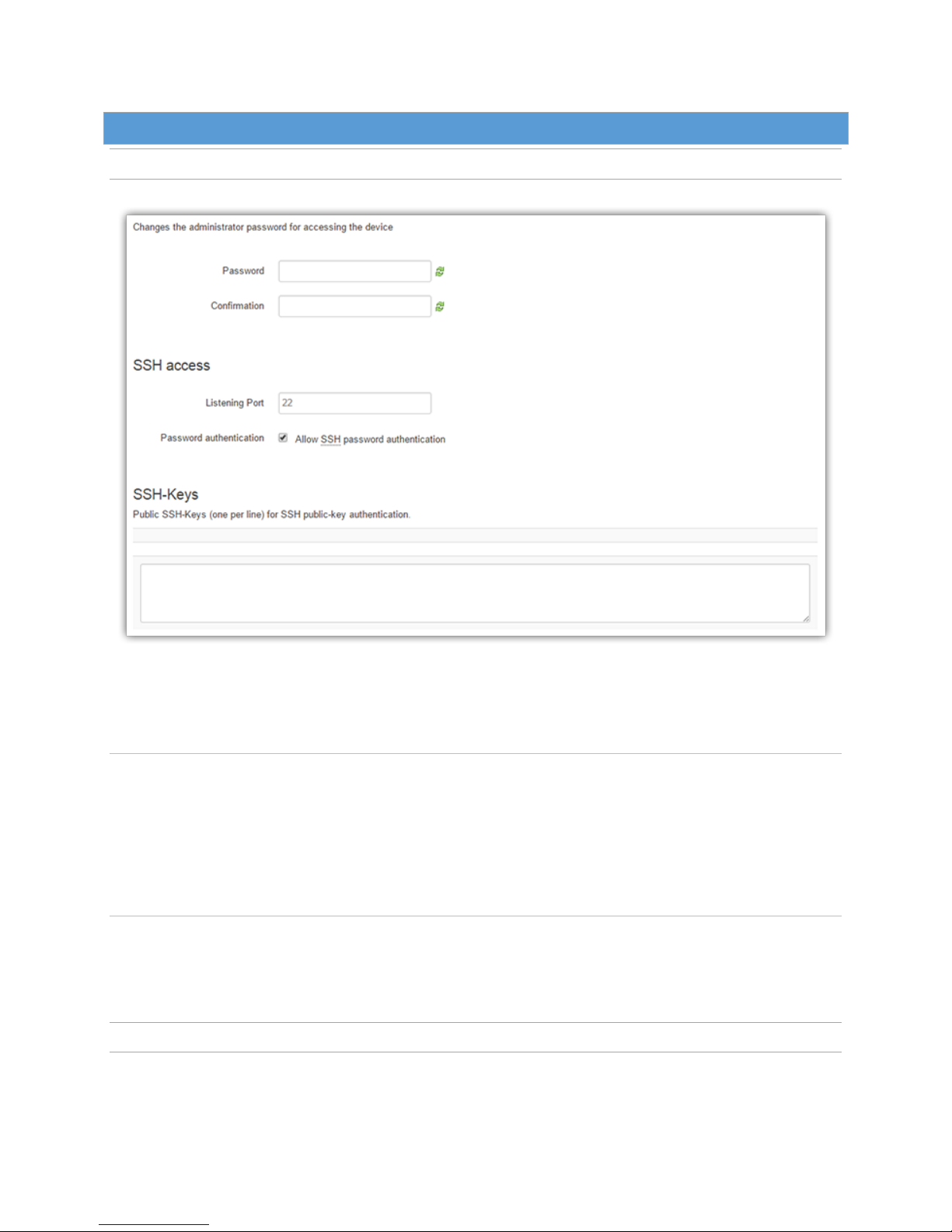
5.12. Adm in
5.12.1. Admin – Access
Figure 40. Admin – Access
Password - Changes the administrator password for accessing the device via the Web Interface.
5.12.1.1. SSH Access
Listening Port - The default SSH server’s port number.
Password Authentication
When the Allow SSH password authentication checkbox is selected, the device will allow the SSH
clients to login using a password. Uncheck this option to disable password-based SSH client login.
The SSH admin account uses the same password as the web server, default is “password.”
5.12.1.2. SSH – Keys
Copy and paste the public key from an SSH client host into the SSH-Keys window and click on “Save &
Apply” to login from a SSH client using a public-private key pairs.
5.12.2. Device Outlook
This section reserved for future use.
ALG-6000 Series LTE Cellular Router | Page 58
Page 66
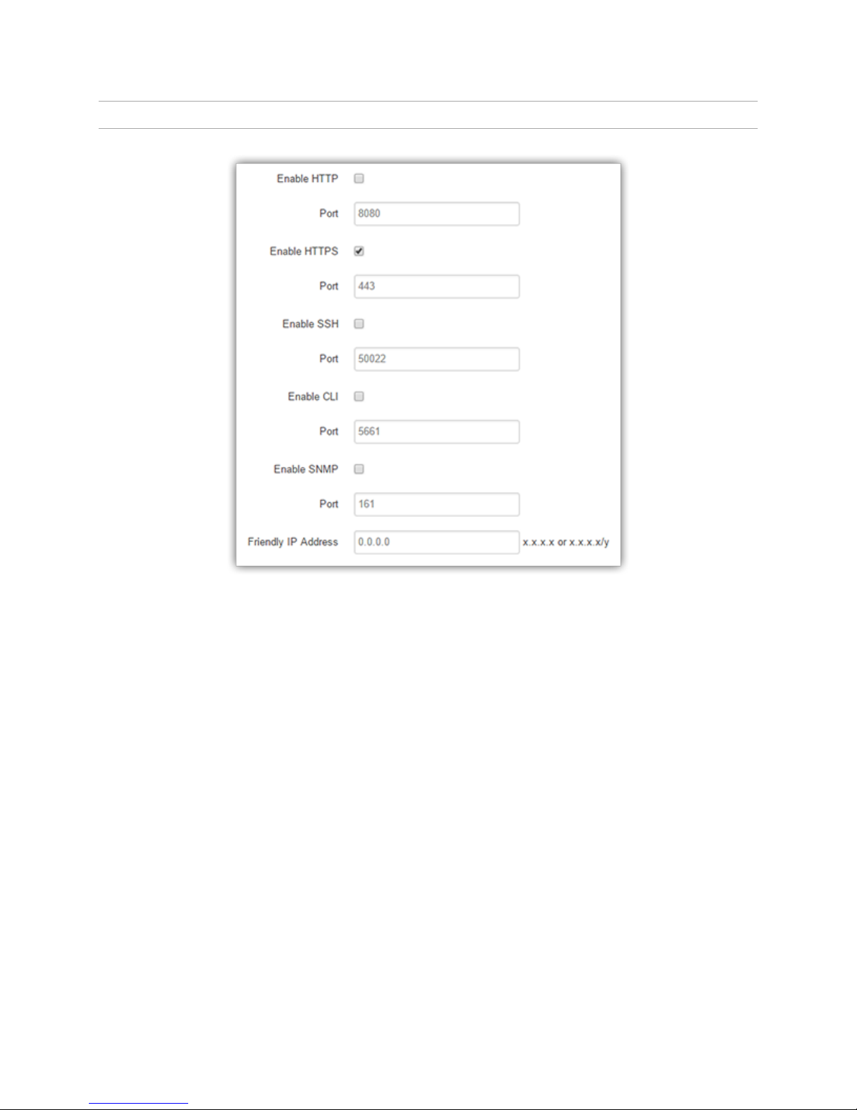
5.12.3. Remote Admin
Figure 41. Access - Remote Admin
This section allows you to enable various remote administration services and set their port numbers. Unless
you have a specific reason to change a port number, choose the default value when enabling a service.
Enable HTTP - Enable remote administration via the standard (not secure) web server interface.
Enable HTTPS - Enable remote administration via the secure web server.
Enable SSH - Enable remote administration via Secure Shell.
Enable CLI - Enable remote administration via CLI.
Enable SNMP - Enable remote administration via the Simple Network Management Protocol.
Friendly IP Address - Specify what IP address is allowed to connect (CIDR notation). The default
0.0.0.0/0 allows all IP addresses to connect.
ALG-6000 Series LTE Cellular Router | Page 59
Page 67
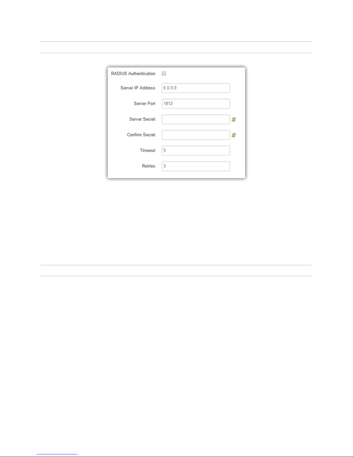
5.12.4. Radius
Figure 42. Admin - Radius settings.
RADIUS Authentication - Enable or disable RADIUS authentication for webpage access.
Server IP Address - The IP address of the RADIUS server.
Server Port - The port of the server.
Server Secret - Sets the secret to use with the server.
Confirm Secret - Re-type the Server Secret to confirm the correct spelling.
Timeout - Specify how many seconds to wait before a retry.
Retries - Specify how many times to retry authenticating with the server before giving up.
5.12.5. Firmware Update
When newer versions of the modem firmware become available, the user can download the proper file from
the Atlas Labs web site and manually update the unit by uploading the new firmware. Time required for
uploading new firmware, depending on the unit, may range from four to fifteen minutes.
Firmware update files are typically given file names of the form ALTLAS-{version}.tar.gz .
Caution: It is important to have a stable power source and ensure that power to the router is not
interrupted during a firmware upgrade.
ALG-6000 Series LTE Cellular Router | Page 60
Page 68
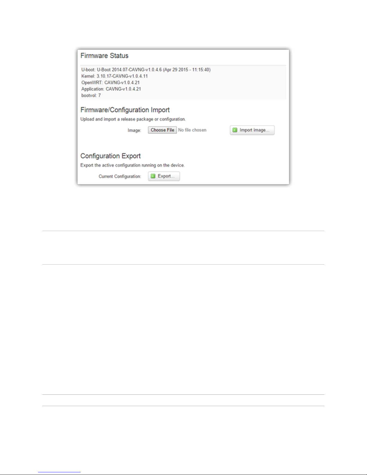
Figure 43. Admin - Firmware Update
5.12.5.1. Firmware Status
This tab displays the currently running version of firmware and its subcomponents
5.12.5.2. Flash Release Package
This section allows you to upgrade to new firmware as new firmware versions become available, as
explained above.
Updates can be done over the local Ethernet connection or over the cellular network if Remote
Administration is enabled, allowing remote access to the router web interface and the Firmware Update
page.
Browse Button - Enter the update file name or you may use the browse button to locate the file
from your hard drive.
Upload Image Button - After selecting the firmware upgrade filename above, press the Upload
button to begin the firmware upgrade process. After the firmware package is selected, check the
Apply default config box and click the Proceed button if the default configuration needs to be
applied. Otherwise click on “Proceed” to install the firmware without applying default
configuration.
5.12.6. System Reset
ALG-6000 Series LTE Cellular Router | Page 61
Page 69

Figure 44 - Admin System Reset
Click the Reboot… button to reset the system. It takes approximately 30 seconds for the system to come
back online.
ALG-6000 Series LTE Cellular Router | Page 62
Page 70

6. Service and Support
6.1. P ro du ct Wa rra nt y, RM A and C on tact Infor ma tion
Atlas Labs LLC guarantees that every ALG-6000 Cellular Modem will be free from physical defects in
material and workmanship for one (1) year from the date of purchase when used within the limits set forth
in the Specifications section of this manual. Extended warranty plans are available.
If the product proves defective during the warranty period, contact Atlas Labs Customer Service to obtain a
Return Material Authorization (RMA).
6.2. R MA R equ es t
Contact Customer Service:
Atlas Labs LLC
115 E City Place Dr
Santa Ana, CA 92705
Phone: (949) 892-5263
When returning a product, mark the RMA clearly on the outside of the package. Include a complete
description of the problem and the name and telephone number of a contact person. RETURN REQUESTS
WILL NOT BE PROCESSED WITHOUT THIS INFORMATION.
For units in warranty, customers are responsible for shipping charges to Atlas Labs LLC. For units returned
out of warranty, customers are responsible for all shipping charges. Return shipping instructions are the
responsibility of the customer.
6.3. P ro du ct Do cum en ta tion
Atlas Labs LLC reserves the right to update its products, software, or documentation without obligation to
notify any individual or entity. Product updates may result in differences between the information provided
in this manual and the product shipped. For the most current product documentation, visit www.atlaslabs.io
for spec sheets.
6.4. T ec hn ica l Sup po rt
Technical support hours: Monday to Friday 9:00 AM to 5:00 PM, Pacific Time
Atlas Labs LLC, 115 E City Place Dr, Santa Ana, CA 92705
Phone: 949.892.5263
ALG-6000 Series LTE Cellular Router | Page 63
Page 71
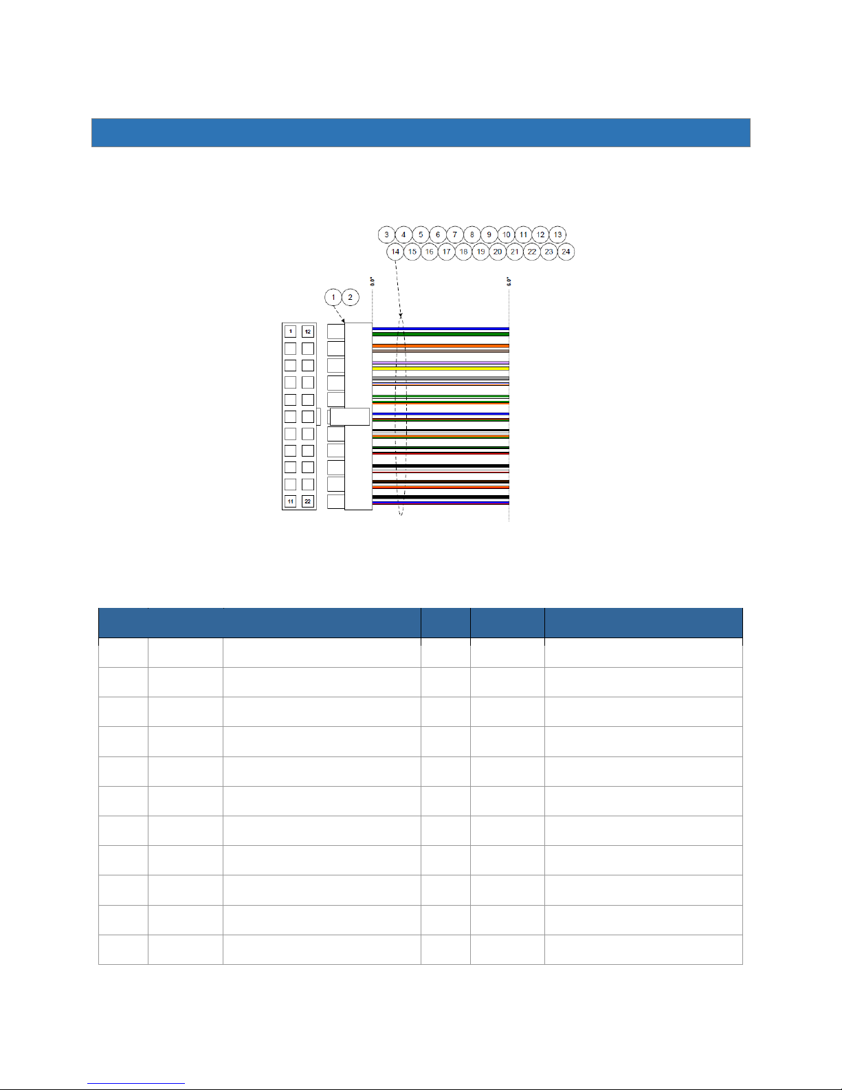
Pin
Signal
Description
Pin
Signal
Description
1
DIN1
Digital Input 1
12
DOUT1
Digital Output 1
2
DIN2
Digital Input 2
13
DOUT2
Digital Output 2
3
DIN3
Digital Input 3
14
DOUT3
Digital Output 3
4
DIN4
Digital Input 4
15
DOUT4
Digital Output 4
5
DIN5
Digital Input 5
16
DOUT5
Digital Output 5
6
DIN6
Digital Input 6
17
DOUT6
Digital Output 6
7
DIN7
Digital Input 7
18
DOUT7
Digital Output 7
8
1BB1
1-Wire Sensor Input 1
19
ADC1
Analog Input 1
9
GND
Ground
20
ADC2
Analog Input 2
10
1BB2
1-Wire Sensor Input 2
21
ADC3
Analog Input 3
11
GND
Ground
22
ADC4
Analog Input 4
7. I/O Port Connector
The ALG-6000 has a 22-pin connector on the back panel that can be used for general purpose analog and
digital inputs.
Figure 45. I/O Port connector pin-out.
ALG-6000 Series LTE Cellular Router | Page 64
Page 72
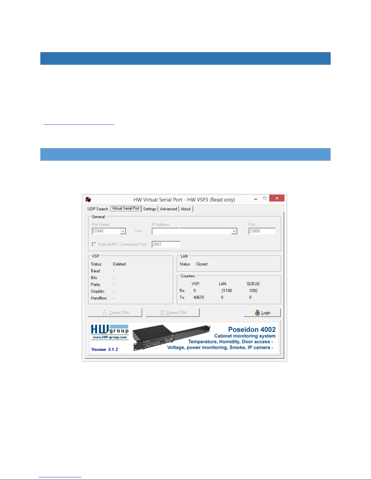
8. Serial Port Emulation
The ALG-6000 may be configured to transmit GPS data to client devices on the local vehicle network over
WiFi or ethernet. The following procedure outlines steps for configuring a Windows laptop with a virtual
serial port connection for support of legacy GPS-enabled applications.
In order to create a virtual serial port on the client machine, the appropriate software must be installed. HW
Virtual Serial Port is a freeware application from HW Group and may be downloaded from their website at
http://www.hw-group.com. At the time of writing, the latest version is HW VSP3 and could be found on the
HW Group website by selecting Software > HW VSP3 from the navigation bar. Follow the instructions on the
site for downloading and installing.
8.1. H W VS P3 Co nfigu ra tion
After VSP3 is downloaded and installed, it must be configured to create a virtual serial port using settings
appropriate to the ALG-6000. To do this, open VSP3 on the client computer to bring up the following screen:
Initially the software will be locked to prevent unauthorized access. Click the Login button in the lower right
of the screen to edit the parameters, then perform the following:
1. Select an available COM port under the Port Name. This will be the virtual COM port to be created
on the client PC.
2. Enter the LAN or WLAN IP address of the ALG-6000 in the IP Address field.
3. Enter 23000 or any other TCP port not used on the ALG-6000.
4. Select the Settings Tab and ensure the following are configured:
ALG-6000 Series LTE Cellular Router | Page 65
Page 73
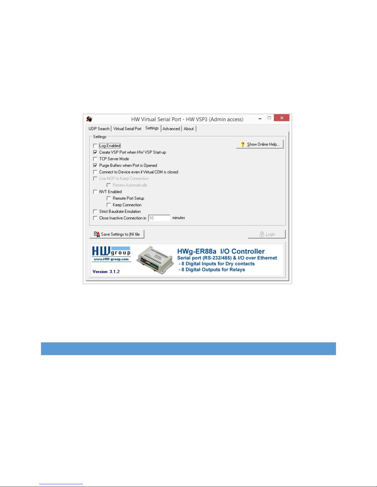
a. Uncheck Log enabled
b. Check Create VSP Port when HW VSP Start-up
c. Uncheck TCP Server Mode
d. Check Purge Buffers when Port is Opened
e. Uncheck Connect to Device even if Virtual COM is closed
f. Uncheck NVT Enabled
g. Uncheck Strict Baudrate Emulation
h. Uncheck Close Inactive Connection
5. Click the Save Settings to INI File button to save settings across reboot cycles.
6. Select the Virtual Serial Port tab, then click the Create COM button.
At this point the virtual COM port should be created. However, no connection may be established until the
ALG-6000 is configured.
8.2. A LG -6 000 C on fig ur ation
Before client devices may be configured to connect to the ALG-6000, the appropriate TCP Port and GPS
format must be configured. To do this, log into the ALG-6000 and select GPS > Settings from the navigation
menu.
Under the GPS Configuration section, set the following settings:
1. Client Index any available sequence
2. Protocol TCP
3. Host Port Number 23000 (or whatever port was used previously to configure VSP3)
4. Report every 1 second
ALG-6000 Series LTE Cellular Router | Page 66
Page 74
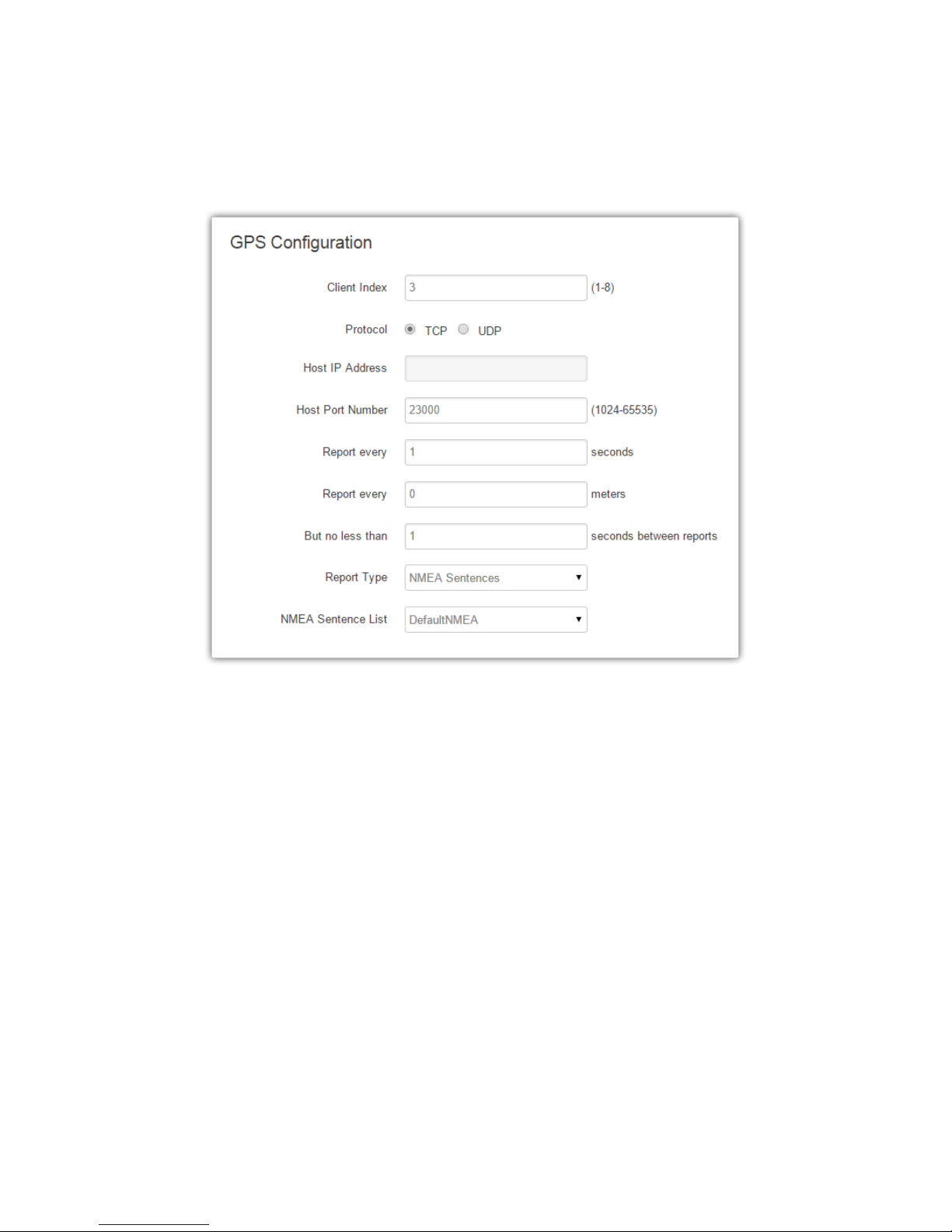
5. Report every 0 meters
6. But no less than 1 second between reports
7. Report Type NMEA Sentences
8. NMEA Sentence List DefaultNMEA (should include at least RMC and GGA)
With the above settings configured, click the Save & Apply button.
ALG-6000 Series LTE Cellular Router | Page 67
Page 75
1
9. Road Safety Integration
The ALG-6000 Cellular Data Router may be configured to integrate with ZOLL’s Road Safety1 system for
real-time transmission of vehicle data to the Road Safety base station using the cellular connection.
In addition to providing remote access in real-time to all Road Safety equipped vehicles, the ALG-6000
allows use of IPSec for encrypting the data connection between the Road Safety base station the vehicle.
9.1. P re re qui si tes
To ensure a reliable connection between Road Safety and the ALG-6000, Atlas Labs strongly recommends
adherence to the following prerequisites.
Activated cellular data plan (highly recommend unlimited or 5GB monthly data plan per vehicle).
Static publicly addressable IP address, or a configured IPSec tunnel with unique private subnet for
each ALG-6000.
NOTE: Additional prerequisites may be required by Road Safety. Please contact your ZOLL Data
representative for more information.
9.2. C on fi gur at ion
For each vehicle to be configured with the ALG-6000 and Road Safety, the following steps must be
completed.
Physical Connection
ALG-6000 Serial Port Configuration
Road Safety Base Station Configuration
9.2.1. Physical Connection
To connect the ALG-6000 with Road Safety’s RS-3000 vehicle computer, connect the COM port on the
ALG-6000 to COM3 or COM4 on the RS-3000 using an RS-3148 cable (available from Road Safety).
9.2.2. ALG-6000 Serial Port Configuration
Log into the ALG-6000’s web interface (see Section 3) and select the Serial Port Settings page.
Under the Serial Port section, select the Road Safety RS-3000 option and click Save:
For additional information on the RescueNet Road Safety system by ZOLL, visit http://www.zolldata.com.
ALG-6000 Series LTE Cellular Router | Page 68
Page 76
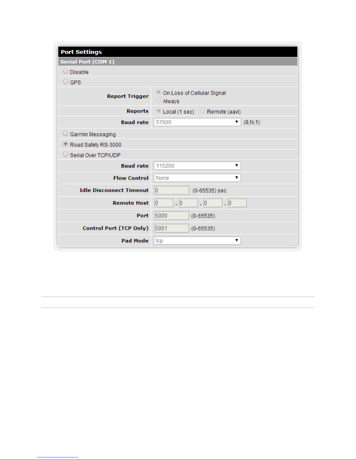
Figure 46. ALG-6000 configuration for use with the Road Safety RS-3000.
Please note that the baud rate, flow control, idle timeout, and other parameters listed under Serial Over
TCP/UDP do not reflect the current settings when Road Safety is selected for the serial port function.
9.2.3. Road Safety Base Station Configuration
To complete the installation, further configuration must be performed on the Road Safety base station,
including building vehicles in the Cellular Link software and assigning a static IP address to them. For
instructions, please contact your ZOLL Data representative.
ALG-6000 Series LTE Cellular Router | Page 69
 Loading...