

AtlasIED Z, Z4, Z2 Owner's Manual
Z Series
High Definition Acoustical System
1601 JACK MCKAY BLVD.
ENNIS, TEXAS 75119 U.S.A.
TELEPHONE: (800) 876-3333
SUPPORT@ATLASIED.COM
– 1 –
AtlasIED.com

Z Series
Owner’s Manual
Table of Contents
Introduction ........................................................................................................................................................................................................... 3
Key Features .......................................................................................................................................................................................................... 3
Applications ............................................................................................................................................................................................................ 3
Package Contents ................................................................................................................................................................................................... 4
Opening the Z Series ............................................................................................................................................................................................. 5
Mounting the Z Series ............................................................................................................................................................................................ 5
Wiring the Z Series I/O Backbox ............................................................................................................................................................................ 9
• Mic / Line Balanced Input
• 3.5mm AUX Input
• Speech Enhancement Control Port
• Fault Control Port
• Speaker Terminals
Z Series Front Panel, Menu Display, and Navigation Controls ..............................................................................................................................10
Navigation Menu Tree ............................................................................................................................................................................................11
Understanding Unique Menu Tree Features ......................................................................................................................................................... 13
Default Ship Mode, Factory Presets, and SHS EQ .............................................................................................................................................. 14
Creating Custom Project Files .............................................................................................................................................................................. 15
Optional Accessories ............................................................................................................................................................................................ 16
• Z-SIGN - Wireless Enhanced Speech Privacy Activation Switch & Visual Indicator
• Z Series App - Enhanced Speech Privacy Activation Switch & System Tuning
• ASP-MG2240S - Wired Enhanced Speech Privacy Visual Indicator
• WPD-SWCC - Wired Enhanced Speech Privacy Activation Switch
Updating the Firmware ..........................................................................................................................................................................................17
Turning On the Z Series ....................................................................................................................................................................................... 18
Streaming Audio and Bluetooth® Paring ............................................................................................................................................................... 18
Specifications ....................................................................................................................................................................................................... 19
Dimensional Drawings ......................................................................................................................................................................................... 22
FCC Compliance ................................................................................................................................................................................................... 23
Warranty ............................................................................................................................................................................................................... 24
1601 JACK MCKAY BLVD.
ENNIS, TEXAS 75119 U.S.A.
TELEPHONE: (800) 876-3333
SUPPORT@ATLASIED.COM
– 2 –
AtlasIED.com

Z Series
Owner’s Manual
Introduction
The Z Series is a multi-zone speech privacy system that also supports background music and paging applications. Model Z2-B is a two-zone speech
privacy system providing 60-watts of total amplification and model Z4-B is four-zone speech privacy system delivering up to 120-watts of amplification.
The Z Series is an all-in-one solution that not only supplies high quality speech privacy, but also can deliver high quality background music and paging.
Mic / line and music inputs each have a five-band equalizer and Hi and Lo pass filters to assure maximum performance. Music inputs incorporate either
analog stereo summed inputs or Bluetooth® streaming. For paging applications, the Z Series incorporates a unique hi-Q feedback filter specifically
tailored to the vocal frequency range. Output limiters are in the audio chain to protect against system overdrive.
Advanced features of the Z Series include separate analog masking generators per zone, 14-day system commissioning ramp per zone, and PC project
design software allows system custom project files to meet installation needs.
For conference room applications where secure speech privacy is required, the Z Series features a Speech Privacy Enhancement mode that can be
engaged while a meeting is in progress. Enhanced Privacy mode applies additional acoustical energy to the surrounding environment, increasing the
privacy levels for the conference room occupants. These unique secured speech filters have been approved and implemented in many installations
around the world including military and government facilities. Activation of the Speech Privacy Enhancement feature is accomplished via hardwired
switch, an iOS® or Android® application, or using an optional wireless desktop / wall mount switch. An optional wired or wireless sign is available for a
visual aid to notify attendees when Enhanced Privacy Mode is active.
Key Features
• Includes Internal, High Efficiency 70.7V Transformer (Cannot be Bypassed for 8Ω Operation)
• Amplified Masking Controller
• 2 Speech Privacy Zones (Model Z2-B)
• 4 Speech Privacy Zones (Model Z4-B)
• 30-Watt 70V Output per Zone
• Out of Box Operational, Featuring AtlasIED Custom Presets
• Enhanced Privacy Mode with Wired and Wireless Signs Available
• Selectable Mic / Line Input for Paging or Recorded Messaging
• 3.5mm Stereo Summed Auxiliary Input for Background Music
• Bluetooth® Streaming for Background Music
• PC Software to Create and Save Custom Project Files
• System Commissioning Ramp on Each Zone
• iOS® and Android® App for System Tuning and Control
• Wireless Speech Enhancement Activation Switch and Sign
Applications
AtlasIED has been developing, manufacturing, assisting and commissioning sound masking systems for over forty years using proprietary Chanaud
masking filters. The Z Series includes a multitude of features enabling it to conform to most design requirements but remains intuitive enough for
simple operation and quick installation. The Z Series is designed to be aesthetically pleasing for office or conference room applications seamlessly
blending in to a variety of decors. Z Series placement is flexible allowing for mounting on a surface, in the wall, or in an equipment rack. The Z2-B
model delivers quality audio and speech privacy in spaces up to 7000 sq ft with two-zones of control flexibility. The Z4-B model features four-zones of
audio with total potential sound masking coverage of up to 14,000 sq ft. This compact integrated solution features out of the box selectable system
configuration presets that are accessible through the front panel display and navigation keys. The combination of these features makes for a simple but
effective speech privacy and audio control solution.
1601 JACK MCKAY BLVD.
ENNIS, TEXAS 75119 U.S.A.
TELEPHONE: (800) 876-3333
SUPPORT@ATLASIED.COM
AtlasIED.com
– 3 –
Z Series
Owner’s Manual
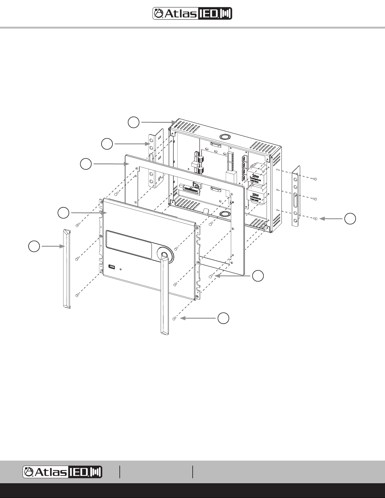
Package Contents
• Z2 or Z4 Unit, Qty 1
• External 100V – 240V to 24DCV UL Power Supply, Qty 1. Z2 = 2.5A, Z4 = 5.0A
• Input Connectors and Speaker Connectors
• Z Series Installation Sheet
F
G
D
A
B
A. Control Panel
B. Control Panel Dress End Caps
C. Control Panel Mounting Screws M3 x 10mm, Qty 6
D. Dress Ring
E. Dress Ring Screws M3 x 5.7mm, Qty 4
F. I/O Backbox
G. In-Wall Support Brackets, Qty 2
H. In-Wall Support Bracket Screws M3 x 5.7mm, Qty 6
H
E
C
Fig 1
1601 JACK MCKAY BLVD.
ENNIS, TEXAS 75119 U.S.A.
TELEPHONE: (800) 876-3333
SUPPORT@ATLASIED.COM
– 4 –
AtlasIED.com
Z Series
Owner’s Manual
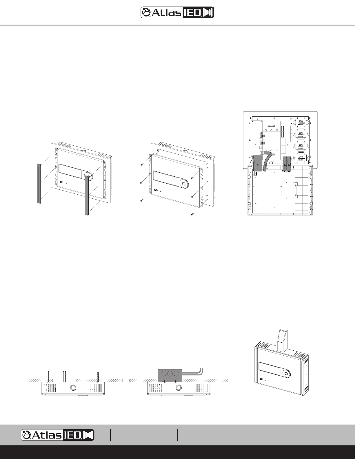
Opening the Z Series
1. Remove the two Control Panel Dress End Caps. These End Caps are held by magnets with guide pins for alignment. They need to be lifted away
from the panel. See Figure 2.
2. Remove the six Control Panel mounting screws.
3. Carefully tilt back the Control Panel to access the I/O Backbox. The Control Panel and I/O Backbox are connected via harness as seen in Figure 4.
Note: Remove the harness connectors from the Control Panel and leave the cables connected to the I/O Backbox.
Fig 2 Fig 3 Fig 4
Mounting the Z Series
The Z Series can be surface mounted, in-wall flush mounted, or rack mounted. Before mounting the Z Series, there are several factors to take into
consideration. Select the best area for wiring infrastructure such as speaker wire, AC mains power, paging cable and background audio source cables.
Placement of the Z Series is also critical when using the Bluetooth® audio streaming feature. The Z Series should be placed within 50ft of the paired
audio source. Powering the Z Series requires use of the included external power supply. It is suggested to place the Z Series within 6ft of a 120V AC
outlet. If this is not possible, the power supply wire for the 24VDC output can be extended up to 50ft. Note: This does not void the warranty as it is
the low voltage wire that is being extended. Note: Pay attention to the DCV polarity when reconnecting the removable Phoenix connector.
Wire Routing
The I/O Backbox wall mounting can be secured by applying screws to a surface, in-wall, or to a 2-gang electrical box. Wiring into the Z Series can be
done via rear 2-gang opening of the I/O Backbox or via electrical conduit 3/4" and 1/2". Knockouts are located on the top and bottom of the I/O Backbox.
For wiring the Inputs and Outputs see “Wiring the Z Series I/O Backbox”.
Wire Entering From Rear Wire Entering Electrical Box Wire Entering Top Conduit
1601 JACK MCKAY BLVD.
ENNIS, TEXAS 75119 U.S.A.
TELEPHONE: (800) 876-3333
SUPPORT@ATLASIED.COM
AtlasIED.com
– 5 –
Z Series
Owner’s Manual
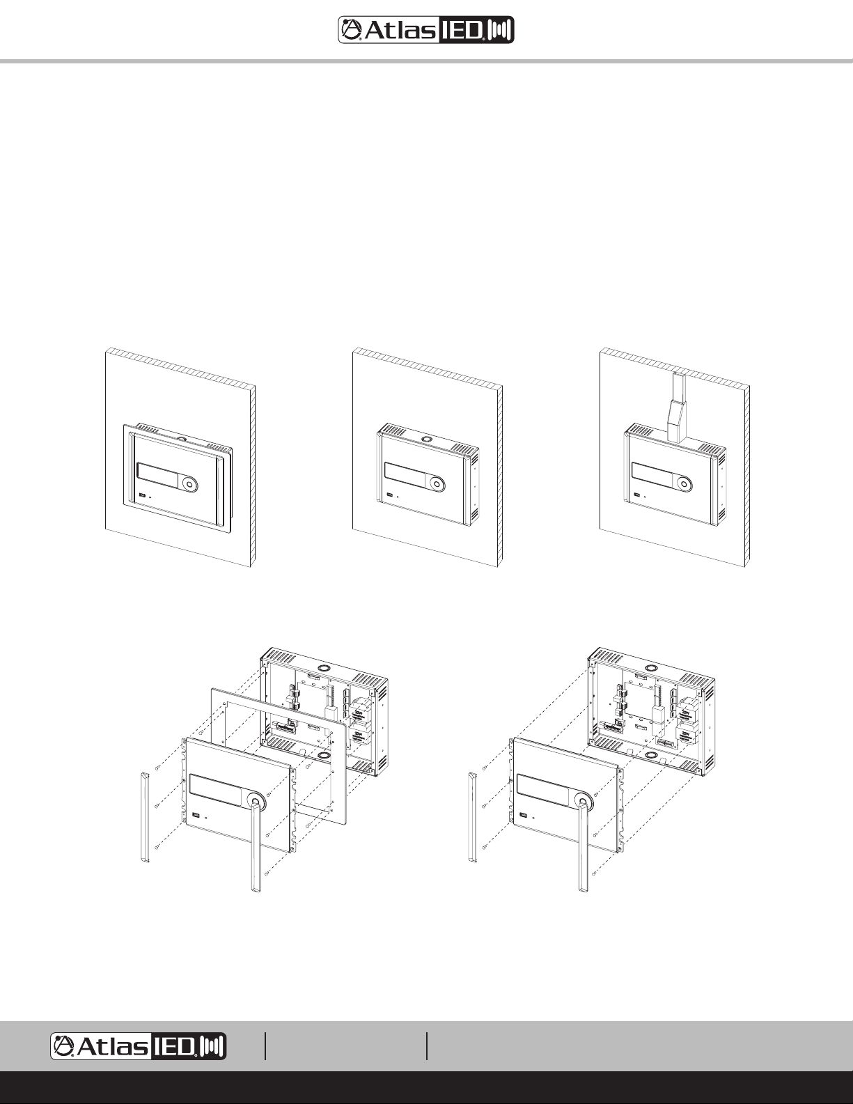
Surface Mount - Direct to Wall
1. Determine the use of the Dress Ring and the wiring routing options. Note: The I/O Backbox Dress Ring and Side Support brackets can be left
assembled or they can be removed.
2. Remove the front Control Panel from the I/O Backbox. The Dress Ring can be left on if preferred. Be careful removing the cables from the Control
Panel PCB.
3. Secure the I/O Backbox to the wall or electrical box.
4. Wire the I/O Backbox. See “Wiring the Z Series I/O Backbox” for details.
5. After the I/O Backbox is wired, re-install the front panel (carefully plug in cable connectors, fold closed, and fasten 6 screws) and apply the two
magnetic end caps. Note: Do not force close or damage may occur. Realign the wires if necessary for smooth panel closure.
Surface Mount
with Dress Ring
Assembly View with Dress Ring
Surface Mount
Surface Mount
without Dress Ring
Surface Mount
without Dress Ring, Top Conduit Wired
Surface Mount
Assembly View without Dress Ring
1601 JACK MCKAY BLVD.
ENNIS, TEXAS 75119 U.S.A.
TELEPHONE: (800) 876-3333
SUPPORT@ATLASIED.COM
– 6 –
AtlasIED.com
Z Series
Owner’s Manual
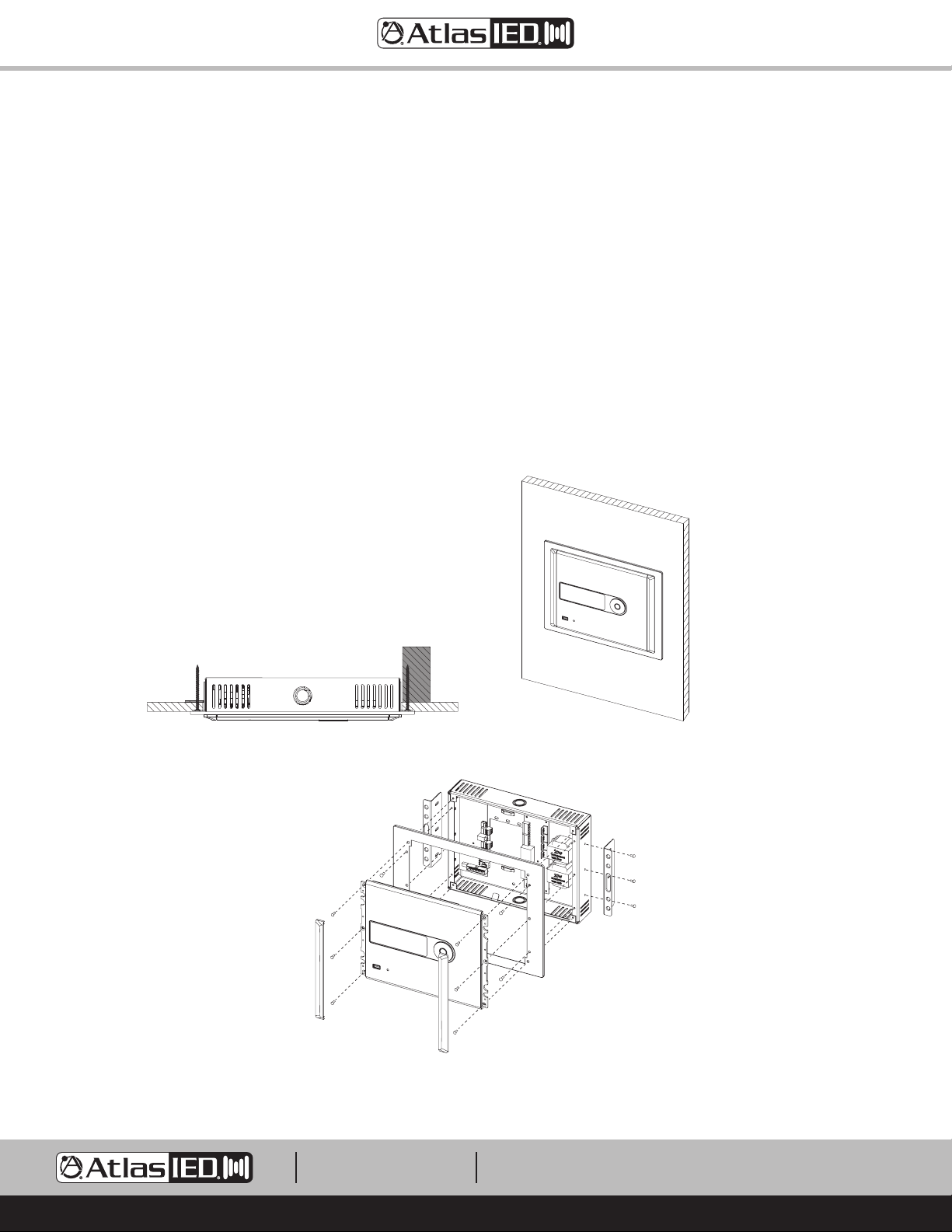
In-Wall Mount
1. Cut a hole in the wall (8.27"H x 10.83" W). Make sure the hole has at least 2" of rear clearance. Note: Aligning one side over a stud is the easiest
and most secure method. See Figure 13.
2. Remove the front Control Panel from the I/O Backbox. Be careful removing the cables from the Control Panel PCB.
3. Remove the Dress Ring from the I/O Backbox to allow access to the side mounted wall mount brackets.
4. Temporarily fit the Z Series into the wall cut-out and adjust the side brackets so the front of the I/O Backbox sits flush to the finished wall.
5. On the opposite side of the stud, use an EZ Anchor or add a small backing block (wood) to screw into. Note: The center of the wall mount bracket
has an opening large enough to allow a drywall screw to hold the wood backing block in place while mounting.
6. After mounting in-wall, re-fasten the Dress Ring to the front of the I/O Backbox.
7. Wire the I/O Backbox. See “Wiring the Z Series I/O Backbox” for details.
8. After the I/O Backbox is wired, re-install the front panel (carefully plug in cable connectors, fold closed, and fasten 6 screws) and apply the two
magnetic end caps. Note: Do not force closed or damage may occur. Realign the wires if necessary for smooth panel closure.
In-Wall Mount
Assembly View with Dress Ring
1601 JACK MCKAY BLVD.
ENNIS, TEXAS 75119 U.S.A.
Fig 14Fig 13
TELEPHONE: (800) 876-3333
SUPPORT@ATLASIED.COM
AtlasIED.com
– 7 –
Z Series
Owner’s Manual
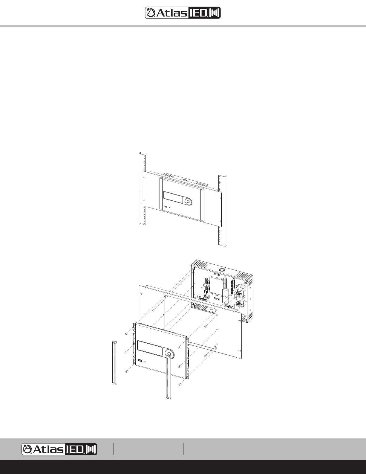
Rack Mount
1. The Rack Mount Kit is not supplied with the Z Series. The ZSERIES-RMK can be ordered at atlasied.com.
2. Remove the front Control Panel from the I/O Backbox. Be careful removing the cables from the Control Panel PCB.
3. Remove the Dress Ring and the two side mounted wall mount brackets from the I/O Backbox. The Rack Mount Plate replaces the Dress Ring.
4. Install the Rack Mount Plate onto the I/O Backbox using the same screws and screw locations used with the Dress Ring.
5. Mount the rack panel into a 19" rack.
6. Wire the I/O Backbox. See “Wiring the Z Series I/O Backbox” for details.
7. After the I/O Backbox is wired, re-install the front panel (carefully plug in cable connectors, fold closed, and fasten 6 screws) and apply the two
magnetic end caps. Note: Do not force closed or damage may occur. Realign the wires if necessary for smooth panel closure.
Fig 16
Rack Mount
Assembly View
1601 JACK MCKAY BLVD.
ENNIS, TEXAS 75119 U.S.A.
TELEPHONE: (800) 876-3333
SUPPORT@ATLASIED.COM
– 8 –
AtlasIED.com
 Loading...