

Atlas IED WMA16-19-HR Installation Manual
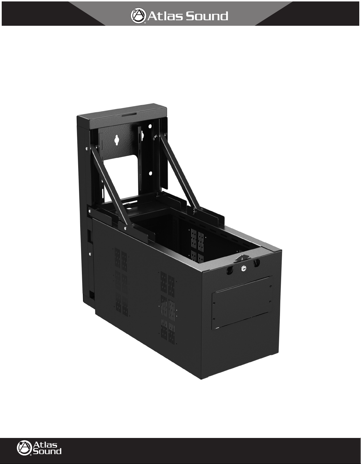
WMA-HR Series
Wall Mount Half Width Rack Equipment Cabinets
1/8
©2013 Atlas Sound L.P. All rights reserved. Atlas Sound is a trademark of Atlas Sound L.P. All other trademarks are the property of their respective owners. All specs are subject to change without notice. P/N 493857 ATS004701 RevA 8/13
1601 JACK MCKAY BLVD.
ENNIS, TEXAS 75119 U.S.A.
TELEPHONE: (800) 876-3333
FAX (800) 765-3435
AtlasSound.com

2/8
WMA-HR Series
Wall Mount Half Width Rack Equipment Cabinets
Key Features
• Available in 12RU and 16RU models.
• Unique swing-down design solution for challenging installation scenarios that enables an integrator and/or contactor to access the back for easy
connection and wire management within very tight spaces.
• Back Box and Main Cabinet are packaged in separate and re-usable cartons. This allows an integrator and/or contactor to ship the Back Box for
immediate installation at the construction site. During that time, the Main Cabinet can be loaded with equipment and re-shipped at a later date.
• Includes front, adjustable 12-gauge Steel Rack Rails. Rails are tapped at 10-32 and finished with black Zinc plating for superior corrosion protection.
• Left and Right Rails are conveniently marked with the RU number elevations (1st RU on the bottom of the cabinet).
• Back Box and Main Cabinet are equipped with provisions for wire management.
• Heavy-duty handles are provided to control the heaviest cabinet load during the swing-down access maneuver.
• The swing-down mechanics reduce the amount of Main Cabinet weight experienced by the integrator and/or contractor.
• Innovative custom lockable slam-latch is provided for easy and secure fastening of the Main Cabinet to the Back-Box.
• Top and bottom of the main cabinet includes removable SPR3-HR solid panels. These panels may be replaced by an optional EFP3-HR fan panel for
further ventilation.
• Perforated vents are located on both sides, top and bottom front surfaces of the Main Cabinet. They provide ventilation for rack-mounted electronics.
• On each cabinet side, there are 4 sets of mount points for industry-standard 119mm fans (105mm mount pattern).
• Unit is designed and constructed in our Ennis, TX facility using durable 16-gauge CRS that is finished in a black electrostatic powder coat. Key
structural components are constructed of an even more durable 14-guage CRS.
• Cabinet comes with 100 black 10-32 Rack Screws to be used for equipment mounting.
• Cabinet is installation-ready for the optional M-1A Cabinet Mount Infrared Repeater System.
• Cabinet is installation-ready for optional “-HR” series cabinet doors such as the MPFD12-HR and MPFD16-HR.
• Atlas Sound offers a complete line of “-HR” series CB (Economy), SPR (Solid) and PPR (Perforated) filler panels.
• Atlas Sound offers a SH1-10-HR Shelf solution for dealing with challenging non-rackable gear.
• The optional VRK-HR Adapter is available for mounting up to 5RU of 19" Width Rack Equipment vertically within 12RU space.
Required Tools
• Razor Knife
• Pliers
• #2 Philips Cross-Drive Screwdriver (Manual or Auto)
• 3⁄8" Hex Socket Driver
• Torque Wrench (optional)
• Tape Measure (optional)
©2013 Atlas Sound L.P. All rights reserved. Atlas Sound is a trademark of Atlas Sound L.P. All other trademarks are the property of their respective owners. All specs are subject to change without notice. P/N 493857 ATS004701 RevA 8/13
1601 JACK MCKAY BLVD.
ENNIS, TEXAS 75119 U.S.A.
TELEPHONE: (800) 876-3333
FAX (800) 765-3435
AtlasSound.com

3/8
WMA-HR Series
Wall Mount Half Width Rack Equipment Cabinets
Cabinet Package Removal
1. Carefully cut the shrink wrap, tape and/or shipping bands holding the Back Box carton and Main Cabinet carton together. Use pliers to remove any
staples.
2. The smaller carton is the Back Box. If required, this carton may be shipped to the construction site for immediate wall installation.
3. Carefully cut cartons open. Use pliers to remove any staples.
4. Pull all the carton flaps to the sides and turn entire contents over, resting upon the carton opening.
5. Carefully pull the carton off the product.
6. If product is to be repacked for future shipment, note the location of the shipping pads on the product. Remove and save all shipping materials.
7. On the Main Cabinet, carefully cut and remove the hardware bag containing keys and rack rail hardware. Keep for future use.
Cabinet Loading Considerations
1. Determine the amount of forward-space that is required by the rack equipment knobs, connections, switches, etc. Use this value to determine
best rail position.
2. If an optional door is to be installed, make sure that no equipment blocks the center slots inside the side panels. These slots capture the door lock
cam. Also, be sure the equipment in the top-most and bottom-most rack units do not protrude within 3⁄4 of an inch from the main cabinet front
surface. The door security flanges occupy this area.
3. If IR remote-controlled equipment and an optional door are to be installed, be sure the door frame does not block the outside IR remote signal. In
cases where blockage is unavoidable, an optional M-1A Cabinet Mount Infrared Repeater System may be mounted in place of the Atlas Sound
logo plug.
4. Measure and set both rails evenly as to the previously determined measurement. Use a 3⁄8" Hex socket driver to torque the rail bolts to 82 ± 2 in-lbs.
5. When installing the rack equipment, use the convenient rack markings to determine the proper rack elevation.
6. Test fit the equipment by laying the main cabinet on its back; all the rack equipment can be laid into place on the rails and adjusted for proper spacing.
7. Once satisfied with the equipment fit, use a #2 Philips driver to install the included 10-32 rack screws. Additional, matching hardware may be
purchased (P/N RSCW100 or P/N RSCW500) as required. Chrome hardware (P/N HK-40) is also available.
8. If additional rear support is required, optional RR Rear Rack Rails may be purchased and utilized within these cabinets.
9. Keep the center of gravity within the Main Cabinet low by installing heavier gear toward the bottom of the cabinet.
10. If any rack equipment has ventilation on the top and bottom of the chassis, do not install gear in the adjacent rack units that may block the
ventilation. If equipment is passively cooled, PPR-HR series perforated filler panels may be used to facilitate cool air availability. Otherwise,
SPR-HR Series or CB-HR Series filler panels may be your best choice.
11. An optional EFP3-HR 3RU fan panel may be used to help facilitate air movement within the cabinet to improve thermal cooling. Note: Fan
reliability is best when used to pull cool air. Additional reliability is gained by using an optional CFT-125 thermostat fan controller to reduce fan usage.
12. Additional air movement may be generated by installing industry-standard 119mm fans (105mm mount pattern) over the side panel perforated
vents; up to 4 fans per side.
13. Use the tie-point slots located on the rear of the main cabinet to help route and retain all electrical and AV cabling. Be sure to leave adequate
tie-points for from-wall electrical and AV service. The back box installer is asked to leave a 4-5 foot service loop. This loop will easily get to any
point within the cabinet.
©2013 Atlas Sound L.P. All rights reserved. Atlas Sound is a trademark of Atlas Sound L.P. All other trademarks are the property of their respective owners. All specs are subject to change without notice. P/N 493857 ATS004701 RevA 8/13
1601 JACK MCKAY BLVD.
ENNIS, TEXAS 75119 U.S.A.
TELEPHONE: (800) 876-3333
FAX (800) 765-3435
AtlasSound.com
 Loading...