

Atlas IED TSD-ML11 Owner's Manual
Owner’s Manual
TSD-ML11
1x1 Mic/Line Preamp
AtlasIED.com – 1 –
Specifications are subject to change without notice.
1601 Jack McKay Blvd. • Ennis, Texas 75119 U.S.A.
Telephone: 800.876.3333 • Fax: 800.765.3435
TSD-ML11
1x1 Mic/Line Preamp
with EQ & Mute

Owner’s Manual
TSD-ML11
1x1 Mic/Line Preamp
AtlasIED.com – 2 –
Specifications are subject to change without notice.
1601 Jack McKay Blvd. • Ennis, Texas 75119 U.S.A.
Telephone: 800.876.3333 • Fax: 800.765.3435
Description
The TSD-ML11 is a high headroom, low noise mic preamp that allows your ‘money channel’ to have
the highest performance possible. Use as a standalone preamp or in conference room systems,
board meetings, courtrooms, council chambers, and public forums system that need mute and push
to talk microphone functions.
The TSD-ML11 features switchable phantom power for powering condenser microphones and
has four EQ cut lters centered at common frequencies to eliminate feedback and control voice
shaping. The variable mic preamp helps further eliminate noise for quiet operation as well as reduces
unwanted coloration and changes in tonality and a 12dB @ 125Hz high pass lter is available on
each mic input to minimize bass rumble and low frequency feedback in the system and ensure
focus and clarity stays on voice sound spectrum. An output limiter/compressor is also included for
system protection to avoid clipping and eliminate distortion. Mic Mute and Mic On control allows
microphones in the system to be push-to-talk enabled or muted for speaker priority.
The TSD-MIX41 is part of a full line of AtlasIED Time Saving Devices. These compact (1.5" x 4" x 2.75")
units are designed to solve some of the common audio system problems in the easiest and in the
most efcient and cost-effective way. All models are made from high quality components and include
removable individual I/O connectors for quick and precise wiring, separate ground terminals for all
I/Os assuring secured connections, and removable level controls that can be replaced with
tamper-proof security covers. The TSDs are highly efcient and meet Energy Star™ standards as one
24V DC power supply (available separately) can power multiple Atlas Time Saving Devices.
Features
• High Quality Microphone Preamp
• Mic/Line I/O via Removable Phoenix Style
Connector
• 125Hz /12dB Low Cut Filter
• Phantom Power
• Four (4) Preset Frequency Notch Filters For
Tone and Feedback Control
• Variable Output Limiter/Compressor
• Mic Mute/Mic On Via Contact Closure
• Input Signal & Peak Indicator LEDs
• High Gain Output for Long Distance
Applications
• Separate Ground Connections
• Cable Management System
• Multiple Mounting Congurations
• Removable Phoenix Style I/O Connectors
• Security Covers Included for All Front Panel
Controls
• Meets Energy Star™ Standards
• Compact Chassis Design
Audio Applications
• Mic Preamp
• Line Preamp
• Line Driver
• Choirs
• Remote Mic Control
Installation
• Churches
• Restaurants
• Sports Bars
• Schools
• Industrial Facilities
• House of Worship
Owner’s Manual
TSD-ML11
1x1 Mic/Line Preamp
AtlasIED.com – 3 –
Specifications are subject to change without notice.
1601 Jack McKay Blvd. • Ennis, Texas 75119 U.S.A.
Telephone: 800.876.3333 • Fax: 800.765.3435
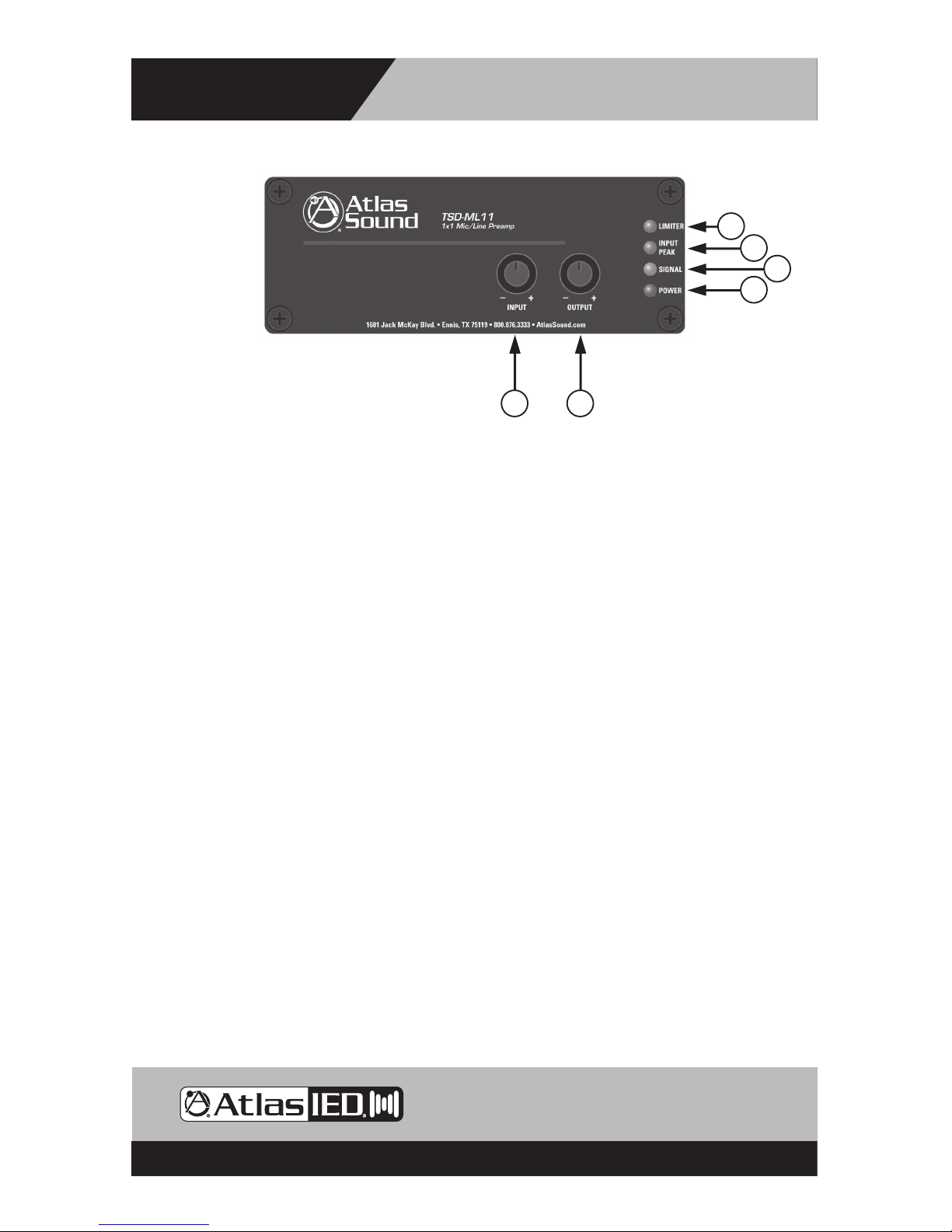
Front Panel Description
1. Input Level Control - Adjusts the gain of the input signal. Turn clockwise to increase the signal
level and counter-clockwise to decrease it. Note: The Input Level Control knob can be removed
and replaced with a supplied security cover to prevent unauthorized adjustment.
2. Output Level Conrol - Adjusts the gain of the output signal. Turn clockwise to increase the signal
level and counter-clockwise to decrease it. Note: The Ouput Level Control knobs can be removed
and replaced with a supplied security cover to prevent unauthorized adjustment.
3. Power LED - Illuminates Blue when 24VDC is present.
4. Input Peak LED - Illuminates Red when the input signal reaches 3dBV below when signal clipping
will occur. Occasional ashing is normal but if this indicator is continuously On, then reduce the
input level using the input level controls on the front panel. There is an LED for each input channel.
5. Signal LED - Illuminates Green when the input signal strength reaches 25mV to verify a signal path.
Note: The LED will not illuminate if the output Level is turned Off.
6. Limiter LED - Illuminates Red when input signal is being limited or clipped. Adjustment of the
Limiter feature should be done after the input gain have been properly set. The input should be
adjusted so the Input Peak LED ashes on signal peaks and then the Output Limiter control can be
set so this LED ashes to indicate that the limiter circuit is active.
5
4
3
6
21
Owner’s Manual
TSD-ML11
1x1 Mic/Line Preamp
AtlasIED.com – 4 –
Specifications are subject to change without notice.
1601 Jack McKay Blvd. • Ennis, Texas 75119 U.S.A.
Telephone: 800.876.3333 • Fax: 800.765.3435
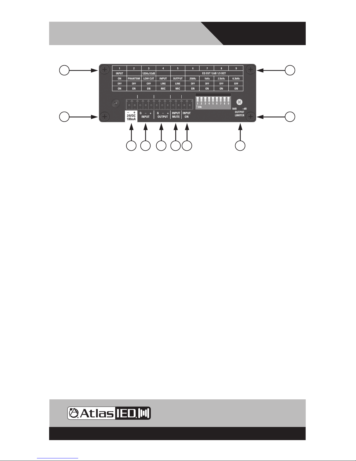
Rear Panel Description
TSD Input/Output connections are removable for easy system wiring. The connector has a 3.5mm
pitch between pins.
1. DC Power Input - Each TSD that requires DC power comes with a 2 position connector for
an external 24VDC power supply (sold separately). Because of the low power consumption, a
single external power supply may power more than one TSD. Refer to the current requirements in
milliamps to match with the appropriate power supply. Note: It is acceptable to exceed the current
of the TSDs but NOT safe to use a power supply that is below the current requirement of the device.
2. Balanced Mic/Line Input - Connects to balanced line or mic level sources. For gain or source input
type selection, refer to the “Dip Switch Function Identication” chart. Note: Unbalanced line inputs
can be inserted with proper wire conguration by connecting the (G) and (-) terminals together.
3. Balanced Mic/Line Output - Provides output for connection to balanced mic/ line level devices.
Note: Unbalanced line leveldevices can be used with proper wire conguration by connecting the
(G) and (-) terminals together.
4. Input Mute - A contact closure across these terminals will mute the microphone so there will be
no output from the TSD-ML11. The contact closure can be either momentary or latching type.
5. Input On - Works when Dipswitch #1 in the Off position. A contact closure across these terminals
will activate the output of the TSD-ML11. Use for remote activation of a microphone.
6. Output Limiter Control - Limiter function sets output level peaks. Rotate clockwise to reduce the
overall output levels by increasing the sensitivity of the input. Rotate counter-clockwise to increate
the output with higher signal peaks. The Limiter LED on the front panel indicates when limiter is in use.
Note: The control knob can be removed and replaced with a supplied security cover to prevent
unauthorized adjustment.
7. Cable Management Retainer Points - Each TSD includes two cable retainer straps for securing
the included cable management retainers. Remove one of the rear panel screws, align the
panel hole with a retainer and rmly tighten the screws.
1 2 3 4 5 6
77
7 7
Owner’s Manual
TSD-ML11
1x1 Mic/Line Preamp
AtlasIED.com – 5 –
Specifications are subject to change without notice.
1601 Jack McKay Blvd. • Ennis, Texas 75119 U.S.A.
Telephone: 800.876.3333 • Fax: 800.765.3435
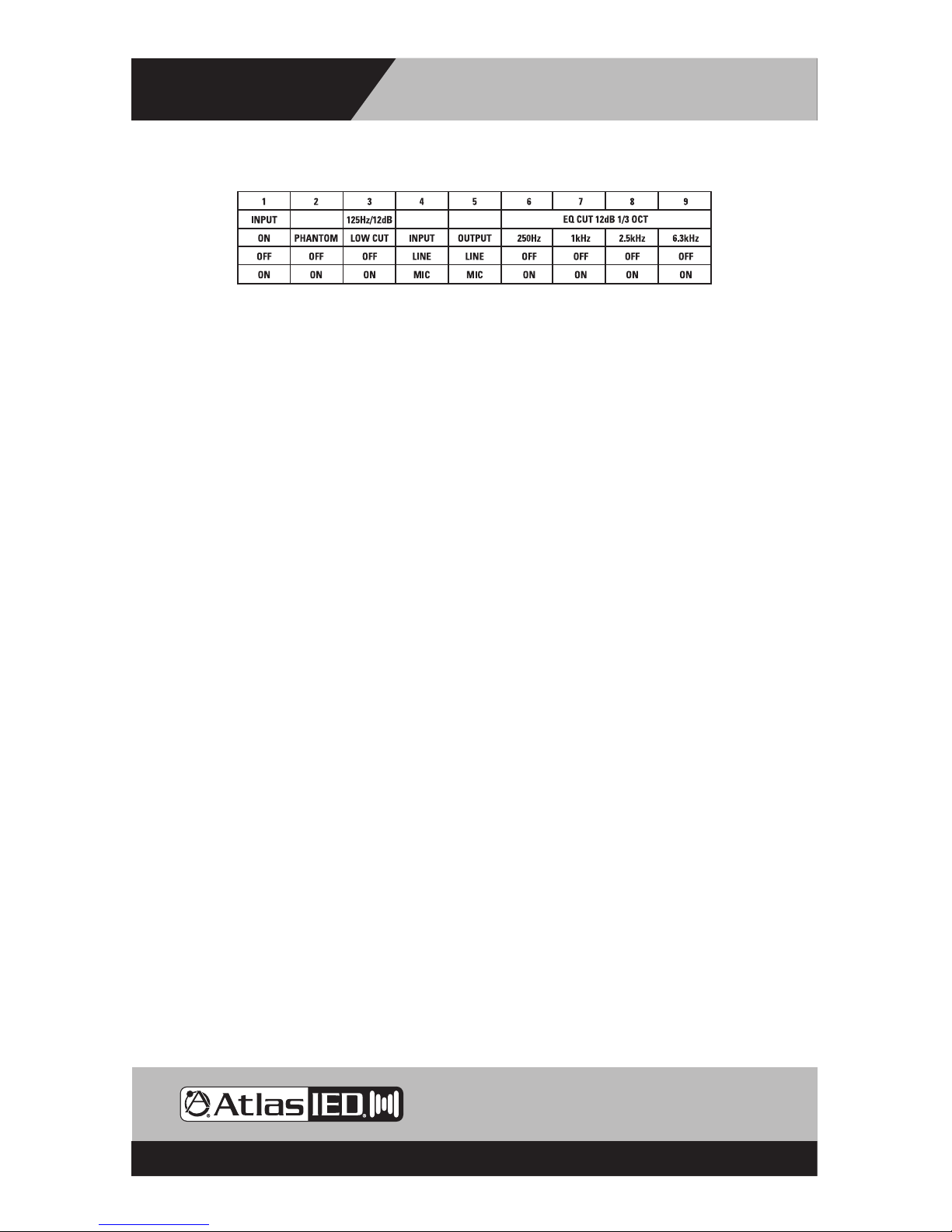
Dip Switch Function Identication
Switch Position
• DIP SW # 1 - When in the up position, a contact closure across the input will turn the Mic or
Line source on. When in the down position, the Input will defeat the Remote On function #5.
• DIP SW # 2 - 24VDC Phantom Power applies power for condenser mic operation. Down position
is On.
• DIP SW # 3 - Low Cut Filter engages at 125Hz with a roll off rate of 12dB per octave. This lter
operates either in the Line or Mic mode and is available on each input. Ideal for vocal
microphones to reduce low frequency energy and to increase intelligibility. Down position is On.
• DIP SW # 4 - Input Mic or Line Select for input gain selection. Up position is Line, down position
is Microphone.
• DIP SW # 5 - Output Mic or Line Select for ouput gain selection. Up position is Line, down
position is Microphone.
• DIP SW # 6,7,8,9 - A cut lter of 12dB per octave is available at four frequencies- 250Hz, 1kHz,
2.5kHz, 6.3kHz- from these respective dip switches. Use these lters to remove feedback to
improve system stability and for tone shaping. Down position is On.
SWITCH FUNCTIONS
 Loading...