

Atlas IED TitanONE T112, TitanONE T112C Installation Manual
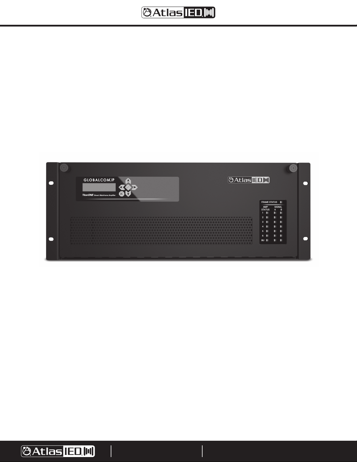
T112 / T112C
TitanONE Smart Mainframe Power Amplifier
Installation Manual
Version: 2.0
5 April 2019
Document: 1225B
©2019 Atlas Sound LP. The Atlas “Circle A”, Soundolier, and Atlas Sound are trademarks of Atlas Sound L.P. IED is a Registered Trademark of Innovative Electronic Designs LLC. All rights reserved.
All other Trademarks are property of their respective owners. No endorsement is implied. Due to continual product development, specifications are subject to change without notice. ATS005973 RevA 9/19 DOC1225B
9701 TAYLORSVILLE ROAD
LOUISVILLE, KENTUCKY 40299 U.S.A.
TELEPHONE: (502) 267-7436
SUPPORT@ATLASIED.COM
AtlasIED.com

Table of Contents
Important Safety Instructions ................................................................................................................................................................................. 3
Safety Symbols ................................................................................................................................................................................................. 3
Safety Considerations ............................................................................................................................................................................................ 4
Safety Precautions ............................................................................................................................................................................................ 4
General Precautions .......................................................................................................................................................................................... 5
Preliminary Precautions .................................................................................................................................................................................... 5
Precautions When Measuring High Voltage Potentials ..................................................................................................................................... 6
Precautions When Working on Energized Equipment ...................................................................................................................................... 6
AC Power Circuits ............................................................................................................................................................................................. 6
Resuscitation .................................................................................................................................................................................................... 6
Introduction ........................................................................................................................................................................................................... 7
Front Panel Description .......................................................................................................................................................................................... 8
Rear Panel Description ........................................................................................................................................................................................... 9
Installing the T112 ..................................................................................................................................................................................................11
Unpacking the Unit ..........................................................................................................................................................................................11
Installing the Unit into a Rack ..........................................................................................................................................................................11
Insert the CPU Card ........................................................................................................................................................................................ 12
Insert the Amplifier Cards ............................................................................................................................................................................... 13
Wiring Diagram ............................................................................................................................................................................................... 14
Connect Speaker Field Wiring......................................................................................................................................................................... 15
Connect Ambient Sensor Field Wiring ............................................................................................................................................................ 15
Connect Audio Inputs ..................................................................................................................................................................................... 15
Connect Logic Inputs ...................................................................................................................................................................................... 16
Connect Fault Relay ........................................................................................................................................................................................ 16
Connect Network Cables ................................................................................................................................................................................ 16
Connect Power Plugs...................................................................................................................................................................................... 16
Providing Battery Backup for the Unit ............................................................................................................................................................. 16
Complete Unit Configuration .......................................................................................................................................................................... 18
Operation / Maintenance / Testing........................................................................................................................................................................ 18
T112 Operation ................................................................................................................................................................................................ 18
T112 Maintenance ........................................................................................................................................................................................... 18
T112 Testing ..................................................................................................................................................................................................... 18
FCC Notice ........................................................................................................................................................................................................... 18
Warranty ............................................................................................................................................................................................................... 20
Operating Instructions .......................................................................................................................................................................................... 21
©2019 Atlas Sound LP. The Atlas “Circle A”, Soundolier, and Atlas Sound are trademarks of Atlas Sound L.P. IED is a Registered Trademark of Innovative Electronic Designs LLC. All rights reserved.
All other Trademarks are property of their respective owners. No endorsement is implied. Due to continual product development, specifications are subject to change without notice. ATS005973 RevA 9/19 DOC1225B
9701 TAYLORSVILLE ROAD
LOUISVILLE, KENTUCKY 40299 U.S.A.
TELEPHONE: (502) 267-7436
SUPPORT@ATLASIED.COM
AtlasIED.com
Important Safety Instructions
Labeling on products and the Installation Instructions & User Manual may use safety related graphical symbols as shown
below to note safety requirements.
Lightning Bolt: The lightning flash with arrowhead symbol, within an equilateral triangle, WARNING symbol, is intended to
alert the user to the presence of un-insulated dangerous voltage within the product’s enclosure that may be sufficient in
magnitude to constitute a risk of electric shock to persons or domestic animals.
WARNING: SHOCK HAZARD - DO NOT OPEN
AVIS: RISQUE DE CHOC ELÉCTRIQUE - NE PAS OUVRIR
WARNING: TO REDUCE THE RISK OF FIRE OR ELECTRIC SHOCK
DO NOT EXPOSE THIS EQUIPMENT TO RAIN OR MOISTURE
AVIS: NE PAS EXPOSER CE MATÉRIEL À LA PLUIE OU L’HUMIDITE
AFIN DE REDUIRE LE RISQUE D’INFLAMMATION OU DE CHOC ELÉCTRIQUE
1. Read these instructions.
2. Keep these instructions.
3. Heed all warnings.
4. Follow all instructions.
5. Do not use this device near water.
6. Clean only with dry cloth.
7. Do not block any ventilation openings. Install in accordance with the manufacturer’s instructions.
8. Do not install near any heat sources such as radiators, heat registers, stoves, or other device that produce heat.
9. Do not defeat the safety purpose of the polarized or grounding-type plug. A polarized plug has two blades with one wider than the other. A
grounding type plug has two blades and a third grounding prong. The wide blade or the third prong are provided for your safety. If the provided
plug does not fit into your outlet, consult an electrician for replacement of the obsolete outlet.
10. Protect the power cord from being walked on or pinched particularly at plugs, convenience receptacles, and the point where they exit from the
device.
11. Only use attachments / accessories specified by the manufacturer.
12. Use only with the cart, stand, tripod, bracket, or table specified by the manufacturer, or sold with the device. When a cart is used, use caution
when moving the cart / device combination to avoid injury from tip-over.
Exclamation Point: The exclamation point within an equilateral triangle, CAUTION symbol, is intended to alert the user to the
presence of important operating and maintenance (servicing) instructions, or a hazard that can damage equipment.
Do not proceed beyond a WARNING or CAUTION notice until you have understood the hazardous condition and have taken
appropriate steps.
Ne continuez pas avant d’avoir pris connaissance du danger et prendre les mesures appropriées.
13. Unplug this device during lightning storms or when unused for long periods of time.
14. Refer all servicing to qualified service personnel. Servicing is required when the device has been damaged in any way, such as power-supply cord
or plug is damaged, liquid has been spilled, or objects have fallen into the device, the device has been exposed to rain or moisture, does not
operate normally, or has been dropped.
15. This product is equipped with a three-wire grounding-type plug, a plug having a third (grounding) pin. This plug will only fit into a grounding-type
power outlet. This is a safety feature. If you are unable to insert the plug into the outlet, contact your electrician to replace your obsolete outlet. Do
not defeat the safety purpose of the grounding-type plug.
16. WARNING: To reduce the risk of fire or electric shock, this device should not be exposed to rain or moisture and objects filled with liquids, such as
a vase, should not be placed on this device.
17. To completely disconnect this equipment from the mains, disconnect the power supply cord plug from the receptacle.
18. The mains plug of the power supply cord shall remain readily operable.
19. Protective earthing terminal. The apparatus should be connected to a mains socket with a protective earthing connection.
©2019 Atlas Sound LP. The Atlas “Circle A”, Soundolier, and Atlas Sound are trademarks of Atlas Sound L.P. IED is a Registered Trademark of Innovative Electronic Designs LLC. All rights reserved.
All other Trademarks are property of their respective owners. No endorsement is implied. Due to continual product development, specifications are subject to change without notice. ATS005973 RevA 9/19 DOC1225B
9701 TAYLORSVILLE ROAD
LOUISVILLE, KENTUCKY 40299 U.S.A.
TELEPHONE: (502) 267-7436
SUPPORT@ATLASIED.COM
AtlasIED.com

WARNING: To reduce the risk of fire or electric shock, do not expose this apparatus to rain, moisture, dripping, splashing, or place objects filled with
liquids on the equipment.
AVERTISSEMENT: Afin de réduire le risque d’incendie ou de choc électrique, n’exposez pas cet appareil à la pluie, à l’humidité, à l’égouttement, aux
éclaboussures, et ne posez pas des objets remplis de liquide sur l’appareil
WARNING: If apparatus is equipped with Class I grounding plugs for safety purposes, it must be connected to MAINS that employ a protective earth
ground connection.
AVERTISSEMENT: si l’appareil est équipé de prises de terre classe I, pour des raisons de sécurité, il doit être branché sur un réseau ayant une prise
de terre de protection.
WARNING: The MAINS plug on this device may be used as the DISCONNECT DEVICE for MAINS power and must remain readily operable.
AVERTISSEMENT: La prise principale de cet appareil peut être utilisé comme DISPOSITIF de DECONNEXION du courant principal et doit rester
facilement accessible.
WARNING: Installation and maintenance of AtlasIED equipment is to be made by trained / qualified personnel and must conform to all applicable local
codes.
AVERTISSEMENT: l’installation et la maintenance des équipements AtlasIED doit être faite par du personnel formé / qualifié et doivent être conformes
à toutes les réglementations locales en vigueur.
WARNING: If unit contains a lithium battery, there is a danger of explosion. Replace only with the same or equivalent type.
AVERTISSEMENT: Si l’unité contient une pile au lithium, il y a un danger d’explosion. Remplacez-la uniquement avec un modèle identique ou
équivalent.
Safety Considerations
Safety Precautions
Personnel properly qualified in the application and use of life safety equipment (“qualified personnel”) shall read this manual carefully before
performing any actions to specify, apply, install, maintain and perform operational tests of AtlasIED systems, and associated products in accordance
with the instructions in this manual. This manual shall be made available to all qualified personnel who operate, test, maintain, or service AtlasIED
systems, and associated products. It is strongly recommend that such personnel read and understand the entire manual.
WARNING: IF SAFETY PRECAUTIONS, INSTALLATION AND TESTING ARE NOT PERFORMED PROPERLY, CONDITIONS COULD EXIST IN
WHICH THE ATLASIED SYSTEM MAY NOT OPERATE, OR MAY OPERATE IMPROPERLY. THIS COULD RESULT IN PROPERTY DAMAGE AND
SERIOUS INJURY OR DEATH TO YOU AND/OR OTHERS.
AVERTISSEMENT: SI LES MESURES DE SECURITE, L’INSTALLATION ET LES ESSAIS NE SONT PAS EFFECTUES CORRECTEMENT, CELA
POURRAIT EMPECHER LE SYSTÈME ATLASIED DE FONCTIONNER, OU DE FONCTIONNER CORRECTEMENT. CELA POURRAIT PROVOQUER
DES DEGATS MATERIELS ET DES BLESSURES GRAVES, OU LA MORT POUR LES AUTRES ET/OU VOUS-MEMES.
It is very important that only responsible, trained personnel are allowed to operate and maintain these systems, and that they use only appropriate
equipment and tools. If a person is not trained, they shall contact the AtlasIED factory for direction on how to operate and maintain an AtlasIED
system.
Unauthorized personnel and equipment must be restricted from the areas of operation.
All operations should be performed carefully, methodically, and without hurrying. Greater effectiveness will be developed by increased familiarity of
personnel with their assignments. During any maintenance operation, if a malfunction occurs or an incorrect indication appears, stop the operation
and determine whether or not it is safe to proceed. Before performing any step in a procedure, be sure that the preceding step has been properly
executed and correct results obtained. Cleanliness and good housekeeping in all installation areas are major factors in effective accident prevention.
Tools and equipment should be maintained in good working order and should always be returned to their proper storage place after usage. Cleaning
agents and other cleaning aids should be removed from the equipment areas immediately upon completing the task at hand.
©2019 Atlas Sound LP. The Atlas “Circle A”, Soundolier, and Atlas Sound are trademarks of Atlas Sound L.P. IED is a Registered Trademark of Innovative Electronic Designs LLC. All rights reserved.
All other Trademarks are property of their respective owners. No endorsement is implied. Due to continual product development, specifications are subject to change without notice. ATS005973 RevA 9/19 DOC1225B
9701 TAYLORSVILLE ROAD
LOUISVILLE, KENTUCKY 40299 U.S.A.
TELEPHONE: (502) 267-7436
SUPPORT@ATLASIED.COM
AtlasIED.com

General Precautions
Changes, modifications, or additions in connection with the AtlasIED system equipment shall not be made without explicit authorization of AtlasIED.
Safety devices found on mechanical, and electrical and electronic equipment are put there for the protection of personnel and equipment. These
devices must be maintained in good working order and operative at all times. Safety devices shall never be removed or bypassed unless specifically
authorized by the AtlasIED factory. Where safety devices have been rendered inoperable by proper and specific authorization, adequate notices shall be
posted to warn personnel of the potential hazard.
Avoid the use of flammable or toxic cleaning fluids, and the use of carbon tetrachloride is prohibited.
Maintenance of the equipment shall be at least what is specified in the AtlasIED manuals and literature, and performed only by qualified personnel.
Whenever operation and maintenance is ongoing, personnel in the equipment areas shall have an effective communication among these areas in order
to protect people if any accident occurs.
Preliminary Precautions
Precautions which are applicable to general electrical or electronic maintenance are as follows:
A. Check yourself. Wear no article that might catch on equipment or that might act as a conductor.
B. Check the working area. The equipment area shall be clean and dry. If possible, stand on a special insulator such as a rubber mat. There should be
ample working space and good lighting.
C. Check the tools. Always use proper tools and check them for their safe condition. Use screwdrivers with plastic handles. Check test equipment
periodically and examine test leads carefully as the slightest break in insulation is dangerous.
D. Check the procedures. Study the entire procedure before taking the first step. Consult the circuit diagram frequently to obtain an understanding of
what is accomplished at each step. Know what is in the equipment and how it differs from others on which you have worked.
E. Be aware that high voltages may be present across terminals that are normally low voltage, due to equipment breakdown. Be careful when
measuring low voltages in equipment containing high voltage circuits.
F. Do not make resistance measurements with power on.
G. Do not work within the equipment without the presence of a person who is capable of rendering aid, and who is familiar with the procedure for
emergency shutdown of the equipment.
©2019 Atlas Sound LP. The Atlas “Circle A”, Soundolier, and Atlas Sound are trademarks of Atlas Sound L.P. IED is a Registered Trademark of Innovative Electronic Designs LLC. All rights reserved.
All other Trademarks are property of their respective owners. No endorsement is implied. Due to continual product development, specifications are subject to change without notice. ATS005973 RevA 9/19 DOC1225B
9701 TAYLORSVILLE ROAD
LOUISVILLE, KENTUCKY 40299 U.S.A.
TELEPHONE: (502) 267-7436
SUPPORT@ATLASIED.COM
AtlasIED.com
Precautions When Measuring High Voltage Potentials
Observe the following precautions when measurements must be performed on circuits with potentials over 48 volts.
A. Do not measure potentials over 48 volts without the presence or assistance of a person who is capable of rendering aid, and who is familiar with
the procedure for emergency shutdown of the equipment.
B. Be sure you are not grounded when you are adjusting equipment or using measuring equipment. Stand on a rubber mat or other insulator if
possible. Be sure the equipment area is clean and dry. In general, use only one hand when servicing live equipment.
C. If a test meter must be held or adjusted while voltage is applied, ground the case of the meter before starting a measurement. Do not touch the
live equipment or personnel working on live equipment while holding the meter. The “common” terminal on some A/C electronic voltmeters is at
ground potential; never connect the “common” terminal to any point above ground potential.
D. High-voltage, high-capacitance capacitors should be discharged before servicing is started.
WARNING! Discharging must be done carefully and judiciously. First ascertain whether there is a built-in bleeder network. If so, wait a
minute or two for the capacitor to discharge through the network. Otherwise, use an external discharge network. This is most important in
the case of high voltage or high capacitance capacitors. If one terminal is connected to ground, connect the discharge network between the other
terminal and ground. If neither terminal of the capacitor is grounded, connect the network across the capacitor terminals. Connecting a short circuit
across the terminals is not recommended. Doing so can produce extremely high currents and a flash which can injure the eyes, vaporize metals, and
cause burns.
AVERTISSEMENT: La décharge doit être faite soigneusement et judicieusement. Vérifier d’abord si il y a un réseau de purgeur incorporé. Si
c’est le cas, attendez une minute ou deux pour que le condensateur se décharge par le réseau. Sinon, utilisez un réseau de décharge externe.
Ceci est très important en cas de haute tension ou des condensateurs à haute capacité. Si un terminal est relié à la terre, connecter le réseau de
décharge entre l’autre terminal et la terre. Si aucun terminal de condensateur est fondé, relier le réseau au terminal du condensateur. La connexion
d’un court-circuit entre les terminaux n’est pas recommandée. Cela peut créé des courants très élevés où des étincelles pourrait blesser les yeux,
fondre les métaux et causer des brûlures.
Precautions When Working on Energized Equipment
When it is necessary to work on energized equipment, think ahead and anticipate every hazard. Never work alone on energized equipment.
Interlock switches are installed on some of the doors and panels to break the power circuits when the enclosure is entered. When it is necessary
to work within such an enclosure on energized equipment, the interlock may be bypassed. Extreme caution should then be exercised, as dangerous
voltages are present within the unit.
AC Power Circuits
Equipment obtaining power from a secondary distribution system should be grounded at all times by means of a third grounding wire on the power
lines. Equipment permanently wired to a secondary distribution system should also be grounded separately by connection to a grounding bus or
ground rod with a sufficiently large conductor to handle the current expected if the secondary source is accidentally shorted to the equipment.
The ground wire should be protected from mechanical damage and periodically inspected for good physical condition.
Personnel should never depend on a switch to remove power from equipment. If the equipment is connected to the secondary distribution system by
means of a power cable, detach the cable from the receptacle before attempting any repairs of removal of chassis.
If the equipment is permanently wired to the secondary distribution system, remove the main fuses or open the power switch. Attach a suitable
warning tag to the switch which will warn personnel not to operate the equipment; only the person who originally attaches the warning tag should be
authorized to remove it.
Resuscitation
Personnel working with or near high voltage should be familiar with modern methods of resuscitation. Such information and training is available from
the Red Cross or local emergency response personnel such as the police and fire department.
©2019 Atlas Sound LP. The Atlas “Circle A”, Soundolier, and Atlas Sound are trademarks of Atlas Sound L.P. IED is a Registered Trademark of Innovative Electronic Designs LLC. All rights reserved.
All other Trademarks are property of their respective owners. No endorsement is implied. Due to continual product development, specifications are subject to change without notice. ATS005973 RevA 9/19 DOC1225B
9701 TAYLORSVILLE ROAD
LOUISVILLE, KENTUCKY 40299 U.S.A.
TELEPHONE: (502) 267-7436
SUPPORT@ATLASIED.COM
AtlasIED.com

Introduction
The T112 Intelligent Amplified Digital Signal Processing System is designed to house, supply power to, and cool up to seven (7) Titan-One Series
power amplifier cards. In addition, the mainframe provides digital audio network connections from an AtlasIED audio network controller such as a
GLOBALCOM®.IP IP100 series ACS. There are two product models covered in this manual: the T112 which uses Dante™ for the audio transport and
the T112C which uses CobraNet™. The only difference in the two models is which CPU card is inserted. For simplicity throughout the manual, the
product will be referred to as the “T112” and it is understood that everything applies to both models. Local program or background music (BGM)
inputs can connect to analog connections located on the back of the mainframe. Six of the amplifier cards function as primary cards to drive connected
loudspeaker circuits. The seventh card functions as a backup that is automatically switched in to the speaker line of a failed card. The T112 may accept
any of the following amplifier card models:
• T302-230V – T1 (TitanONE) 300W Total, 2 CH x 150W, 100V
• T302-120V – T1 (TitanONE) 300W Total, 2 CH x 150W, 70V
• T602-230V – T1 (TitanONE) 600W Total, 2 CH x 300W, 100V
• T602-120V – T1 (TitanONE) 600W Total, 2 CH x 300W, 70V
• T1202-230V – T1 (TitanONE) 1200W Total, 2 CH x 600W, 100V
• T1202-120V – T1 (TitanONE) 1200W Total, 2 CH x 600W, 70V
In addition, it may accept the following line driver cards:
• T2LD-120V - T1 (TitanONE) 2 CH Line Driver for T112 Mainframe
• T2LD-230V - T1 (TitanONE) 2 CH Line Driver for T112 Mainframe
Digital signal processing (DSP) is provided on each of the 12 channels and includes level controls, page routing, automatic ducking of background
music, equalization (up to eight (8) parametric bands per amplifier channel plus high-pass filter), signal delay, and AtlasIED’s patented technology for
ambient analysis-based automatic level control, via built-in sensor connections on the rear.
Note: If this device is used as part of a life safety or mass notification system that is required to comply with standards such as UL 864, UL 2572
or ULC S576, or with building codes like NFPA 72, certain measures should be observed with how the device gets it power, how field wiring
is done, how the device is supervised and how the device is configured via its software. There are notifications in gray boxes such as this one
throughout the document which point out these areas. It is the installer’s responsibility to observe and take them into account in designing a
complete system that meets the requirements of any of these standards / codes.
Note for Mass Notification Systems: The T112 and optional cards are listed for use with a Mass Notification System, but it is the responsibility
of the installer to conduct tests on the completed system to determine compliance of the installation. These installation tests should include the
following:
1. Operation Tests: Per Section 31 of UL 864, Section 10.2 of ULC S527, Sections 32 through 35 of UL 2572, and Sections 31 through 33 of
ULC S576
2. Common Performance and Monitoring for Integrity: Communication LInke: Per Section 41.5 of UL 2573 and Sections 39.7 and 39.8 of
ULC S576
3. Charging Current Test: Per Section 69 of UL 864, Section 10.5 of ULC S527, Section 55 of UL 2572 and Section 53 of ULC S576
©2019 Atlas Sound LP. The Atlas “Circle A”, Soundolier, and Atlas Sound are trademarks of Atlas Sound L.P. IED is a Registered Trademark of Innovative Electronic Designs LLC. All rights reserved.
All other Trademarks are property of their respective owners. No endorsement is implied. Due to continual product development, specifications are subject to change without notice. ATS005973 RevA 9/19 DOC1225B
9701 TAYLORSVILLE ROAD
LOUISVILLE, KENTUCKY 40299 U.S.A.
TELEPHONE: (502) 267-7436
SUPPORT@ATLASIED.COM
AtlasIED.com
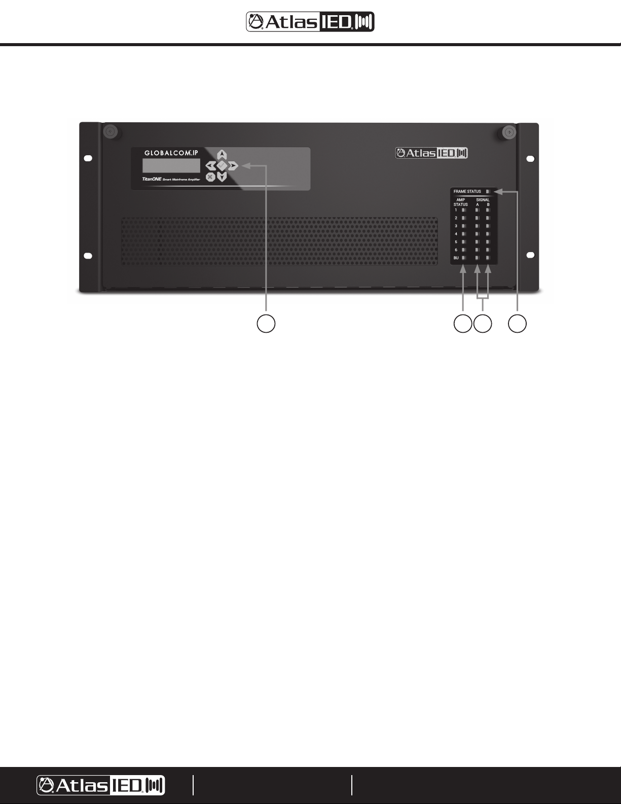
Front Panel
12 34
1. Overall Status Indicator - This is a tri-color LED that indicates the following conditions:
• Slow Flash Green - The unit is powered up and operating normally.
• Quick Flash Green - The unit is powered up, but in power save mode, i.e., the CPU is running, but the amplifiers are powered off in between
announcements and supervision checks.
• Solid Yellow - The unit has a fault of some kind (may be checked on LCD readout).
• Flashing Yellow - The case is open and the power amps have been powered off for operator safety.
• Off - The unit does not have power.
Note: If a solid green indication is seen, this should be considered an abnormal condition in which either the internal processor is not running
normally or communication with the front panel indicators has failed.
2. Amp Status Indicators - This is a tri-color LED that indicates the following conditions:
• Solid Green - The amplifier is powered up and operating normally.
• Solid Yellow - The amplifier or one of the speaker lines attached to it has a fault condition. This includes conditions such as total amplifier failure
(e.g., blown fuse or manual power switch in the off position), speaker line ground fault, speaker line short, and speaker line break.
• Solid Red - The amplifier is processing audio for an alarm (emergency / evacuation message).
• Off - The amplifier is powered off by the internal processor or no amplifier is inserted in that slot.
3. Signal Presence / Clipping Indicators - This is a tri-color LED for each amplifier channel A and B that indicates the following conditions:
• Flickering / Solid Green - This indicates signal presence above detection threshold. This can flicker as the signal goes above and below the
threshold, becoming solid if (averaged) signal stays above the threshold.
• Flickering / Solid Yellow - This indicates signal is being clipped. This may be seen as alternating green-yellow as the signal goes above or below
the clipping level, or solid yellow if it stays above the threshold.
• Flickering / Solid Red - This indicates signal presence above the detection threshold, and that the channel is processing audio for an alarm
(emergency / evacuation message). This may alternate red-yellow as the signal goes above or below the clipping level.
4. LCD Panel & Navigation Buttons - This section provides a user interface for viewing faults or performing some settings / interactions with the
mainframe.
©2019 Atlas Sound LP. The Atlas “Circle A”, Soundolier, and Atlas Sound are trademarks of Atlas Sound L.P. IED is a Registered Trademark of Innovative Electronic Designs LLC. All rights reserved.
All other Trademarks are property of their respective owners. No endorsement is implied. Due to continual product development, specifications are subject to change without notice. ATS005973 RevA 9/19 DOC1225B
9701 TAYLORSVILLE ROAD
LOUISVILLE, KENTUCKY 40299 U.S.A.
TELEPHONE: (502) 267-7436
SUPPORT@ATLASIED.COM
AtlasIED.com
 Loading...