

Atlas IED DPA404 Users Manual
Owner’s Manual
DPA404 / DPA804
Digital Power Amplifiers
DPA Series
Digital Power Amplifiers
1601 Jack McKay Blvd. • Ennis, Texas 75119 U.S.A.
Telephone: 800.876.3333 • Fax: 800.765.3435
– 1 – AtlasIED.com
Specifications are subject to change without notice.

DPA Series
Digital Power Amplifiers
Owner’s Manual
Table of Contents
Important Safety Instructions .................................................................................................................. 3
Introduction ............................................................................................................................................ 5
Key Features ........................................................................................................................................... 5
DPA Amplifier Configuration ................................................................................................................... 6
Front Panel Description ........................................................................................................................... 8
Rear Panel Description ...........................................................................................................................10
Accessory Card Slot ...............................................................................................................................11
Accessing the GUI Control Panel .......................................................................................................... 12
I. Direct Connection via Ethernet ....................................................................................................... 12
II. Web Browser via Network Router ................................................................................................. 13
III. AtlasIED DPA Site Manager Software .......................................................................................... 13
IV. Smartphone or Tablet .................................................................................................................... 14
V. Static IP - Accessing the DPA Outside the Local Network ............................................................ 15
Resetting the DHCP .............................................................................................................................. 15
Identifying the Firmware Version ........................................................................................................... 16
GUI Pages Defined .................................................................................................................................17
User / Home Page .............................................................................................................................17
Password Login ...................................................................................................................................17
Setup Page ......................................................................................................................................... 18
Amp Configuration Page .................................................................................................................... 19
Mute, Link & Port Assign Page .......................................................................................................... 20
Input & Output Router Page .............................................................................................................. 21
High & Low Pass Filter Page ............................................................................................................. 22
Output EQ Page ................................................................................................................................. 23
Output Level Page ............................................................................................................................. 24
Output Delay Page ............................................................................................................................. 25
Output Limiter Page ........................................................................................................................... 26
Remote Level Control Port Assignment & Wiring .............................................................................. 27
Input Mute Assignment ........................................................................................................................ 30
Accessory Card Installation ................................................................................................................... 32
Installation and Considerations ............................................................................................................. 32
Understanding the 3 AC Power Consumption Idle States .................................................................... 33
Changing From 115V - 120V to 220V-240V Operation ........................................................................... 34
Specifications ........................................................................................................................................ 35
Warranty ................................................................................................................................................ 40
1601 Jack McKay Blvd. • Ennis, Texas 75119 U.S.A.
Telephone: 800.876.3333 • Fax: 800.765.3435
AtlasIED.com – 2 –
Specifications are subject to change without notice.
Owner’s Manual
DPA Series
Digital Power Amplifiers
Important Safety Instructions
The lightning flash with arrowhead symbol within an equilateral triangle,
is intended to alert the user to the presence of uninsulated “dangerous
voltage “ within the product’s enclosure that may be of sufficient
magnitude to constitute a risk of electric shock to persons.
WARNING: SHOCK HAZARD - DO NOT OPEN
AVIS: RISQUE DE CHOC ELÉCTRIQUE - NE PAS OUVRIR
WARNING: TO REDUCE THE RISK OF FIRE OR ELECTRIC SHOCK
DO NOT EXPOSE THIS EQUIPMENT TO RAIN OR MOISTURE
AVIS: NE PAS EXPOSER CE MATÉRIEL À LA PLUIE OU L’HUMIDITE
AFIN DE REDUIRE LE RISQUE D’INFLAMMATION OU DE CHOC ELÉCTRIQUE
1. Read these instructions.
2. Keep these instructions.
3. Heed all warnings.
4. Follow all instructions.
5. Do not use this device near water.
6. Clean only with dry cloth.
7. Do not block any ventilation openings. Install in accordance with the manufacturer’s instructions.
8. Do not install near any heat sources such as radiators, heat registers, stoves, or other devices that produce heat.
9. Do not defeat the safety purpose of the polarized or grounding-type plug. A polarized plug has two blades with one wider than the
other. A grounding type plug has two blades and a third grounding prong. The wide blade or the third prong are provided for your
safety. If the provided plug does not fit into your outlet, consult an electrician for replacement of the obsolete outlet.
10. Protect the power cord from being walked on or pinched particularly at plugs, convenience receptacles, and the point where they
exit from the device.
11. Only use attachments/accessories specified by the manufacturer.
12. Use only with the cart, stand, tripod, bracket, or table specified by the manufacturer, or sold with the device. When a cart is used,
use caution when moving the cart / device combination to avoid injury from tip-over.
The exclamation point within an equilateral triangle is intended to
alert the user to the presence of important operating and maintenance
(servicing) instructions in the literature accompanying the product.
13. This product is equipped with a three-wire grounding-type plug, a plug having a third (grounding) pin. This plug will only fit into a
grounding-type power outlet. This is a safety feature. If you are unable to insert the plug into the outlet, contact your electrician to
replace your obsolete outlet. Do not defeat the safety purpose of the grounding-type plug.
14. Unplug this device during lightning storms or when unused for long periods of time.
15. Refer all servicing to qualified service personnel. Servicing is required when the device has been damaged in any way, such as
power-supply cord or plug is damaged, liquid has been spilled, or objects have fallen into the device, the device has been exposed
to rain or moisture, does not operate normally, or has been dropped.
16. WARNING: To reduce the risk of fire or electric shock, this device should not be exposed to rain or moisture and objects filled with
liquids, such as a vase, should not be placed on this device.
17. To completely disconnect this equipment from the mains, disconnect the power supply cord plug from the receptacle.
18. The mains plug of the power supply cord shall remain readily operable.
19. Protective earthing terminal. The apparatus should be connected to a mains socket with a protective earthing connection.
1601 Jack McKay Blvd. • Ennis, Texas 75119 U.S.A.
Telephone: 800.876.3333 • Fax: 800.765.3435
– 3 – AtlasIED.com
Specifications are subject to change without notice.
DPA Series
Digital Power Amplifiers
Owner’s Manual
WARNING - When The Device Is In Use
• WARNING: For the terminals marked with symbol of may be of sufficient magnitude to constitute a risk of electric shock. The
external wiring connected to the terminals requires installation by an instructed person or the used of ready-made leads or cords.
• WARNING: The apparatus shall not be exposed to dripping or splashing and that objects filled with liquids, such as vases, shall not be
placed on apparatus.
• WARNING: The mains plug is used as disconnect device, the disconnect device shall remain readily operable.
• To prevent electric shock, do not remove the product cover as there are high voltage components inside. Refer all servicing to
AtlasIED.
• Should any of the following irregularities occur during use, immediately switch off the power, disconnect the power cord from the
AC outlet and contact AtlasIED. Do not to attempt to continue operation with the product as this may cause fire or electric shock:
• Smoke or strange smell coming from the unit.
• If the product falls or the case is damaged.
• If water or any metallic objects falls into the product.
• If the power supply cord is damaged in any way.
• If the unit is malfunctioning.
• Do not insert or drop metallic objects or flammable materials into the ventilation holes of the product's cover, as this may result in
electric shock or fire.
• Do not place any containers with liquid or metallic objects on the top of the product. If any liquid spills into the unit, fire or electric
shock may result.
• Never operate this product or touch the power supply cord during an electrical storm, electric shock may result.
• Never exceed the power rating on the product when connecting equipment. Fire and/or property damage may result.
• Operate the product only with the voltage specified on the unit. Fire and/or electric shock may result if a higher voltage is used.
• Do not modify, kink, or cut the power cord. Do not place the power cord in close proximity to heaters and do not place heavy objects
on the power cord, including the product itself, doing so may result in fire or electrical shock.
• Ensure that the safety ground terminal is connected to a proper ground. Never connect the ground to a gas pipe as a catastrophic
disaster may result.
• Be sure the installation of the product is stable, avoid slanted surfaces as the product may fall and cause injury or property damage.
CAUTION - When Installing The Product
• Plugging in or unplugging the power cord with wet hands may result in electric shock.
• Never move the unit with the power cord plugged into the wall, as damage to the power cord may result.
• When unplugging the cord from the wall, grasp the plug, NOT the cord.
• Never install this product in humid or dusty locations, nor in direct sunlight, near sources of heat, or in areas where sooty smoke or
steam are present. Fire and electric shock may result.
• Keep all sides of the unit at least 31/2" away from objects that may obstruct air flow to prevent the unit's internal temperature rise.
CAUTION - When The Product Is In Use
• Never place heavy objects on the product, causing it to fall and/or break, resulting in personal injury and property damage. In
addition, the product itself may fall and cause injury and property damage.
• Contact AtlasIED for instructions on cleaning the inside of the unit. Large accumulations of dust inside the unit may result in heat
buildup and fire.
• Ensure that the power supply plug is securely plugged into the wall outlet. Never allow dust to accumulate on the power plug or
inside the wall outlet.
• When cleaning the unit or the unit is not to be operated for an extended period, unplug the power cord from the wall.
1601 Jack McKay Blvd. • Ennis, Texas 75119 U.S.A.
Telephone: 800.876.3333 • Fax: 800.765.3435
AtlasIED.com – 4 –
Specifications are subject to change without notice.

Owner’s Manual
DPA Series
Digital Power Amplifiers
Introduction
The AtlasIED DPA amplifier series features a combination of flexibility, performance and control to provide high value features for
applications that require more than just great sound. The network based DPA404 and DPA804 are DSP controlled four-channel
amplifiers that can be configured in three different amplification arrangements to meet the design requirements of any installation.
These DPA models are factory preconfigured in a four-channel 70V mode. If the design requires four channels of low impedance
amplification, the DPA amplifiers can be configured as four-channel models with either 4-Ohm or 8-Ohm load impedances. Many
system designs require both low and high impedance amplification. These DPA models can be configured to deliver 70V / 100V for a
paging / background system on two channels plus two additional 4/8-Ohm amplifier channels for a foreground stereo application.
These DPA models come standard with four balanced line inputs and an accessory slot for an optional DPA-DAC4 four-channel Dante™
receiver card or a DPA-AMIX (2) mic / line, (2) AUX input card, giving the DPA404 and DPA804 a total of 8 inputs. All inputs can be
mixed and routed to any of the four amplifier channels. All four amplifier channels have an assortment of DSP tools including level
controls, EQ’s, limiters, high & low pass filters, and delay to provide flexibility for a range of applications.
DPA Series amplifiers feature either local or network control making them a true “game changer” in the commercial audio world. The
output level can be assigned to either the front panel potentiometers or to the onboard GUI. Wired remote level control and input select
can be configured to allow simple control for the end user. Each unit also features GUI based input and output level metering along
with assignable mute functions that are triggered via an audio signal or contact closure. Access to the DSP settings is accomplished via
computer, tablet or mobile device using a web browser. All settings can be password protected.
The DPA series amplifiers also include PC based site manager software that automatically searches within a specific network for all
DPA amplifiers on the network. It will list them and allow single click access to any unit. The DPA Site Manager software can do a
variety of functions besides locating IP addresses including fault reporting, input & output status, standby status and remote activation
via a scheduler timer.
The DPA404 and DPA804 are ready to use, out of the box in four-channel 70V / 100V mode, with no configuration or network
connectivity required making them a cost effective solution even for applications that do not require processing or network control.
Key Features
DPA404 Configuration Power Levels
• 4 x 100 Watt 70V (Factory Default)
• 4 x 100 Watt 100V
• 4 x 75 Watt 8Ω
• 4 x 50 Watt 4Ω
• 2 x 100 Watt 70V / 100V & 2 x 75 Watt @ 8Ω
• 2 x 100 Watt 70V / 100V & 2 x 50 Watt @ 4Ω
DPA804 Configuration Power Levels
• 4 x 200 Watt 70V (Factory Default)
• 4 x 200 Watt 100V
• 4 x 150 Watt 8Ω
• 4 x 100 Watt 4Ω
• 2 x 200 Watt 70V / 100V & 2 x 150 Watt @ 8Ω
• 2 x 200 Watt 70V / 100V & 2 x 100 Watt @ 4Ω
• GPIO - Assignable for remoter level & mute
• No computer required to use
• Configurable DSP
• PC, iOS®, & Android® controllable
• User page with assignable input & output level control
• Site manager software with network auto-discovery, fault
reporting, input & output status, standby status and remote
activation via a scheduler timer
• On board web GUI for remote monitoring of status & levels
• Mute assignments triggered via audio signal or contact closure
• APD - auto power down with audio sense turn on
• 4 balanced inputs (up to 8 inputs with optional accessory card)
• Optional accessory card slot for a DPA-DAC4 four-channel
Dante™ receiver card or a DPA-AMIX (2) mic / line, (2) AUX
input card
• Assignable level controls, on board GUI (security password
protected) or by front panel pots with tamper deterring covers
• Assignable remote level control when used with optional
WPD-VC10K
• DPA amplifier site manger software
• DPA amplifier discovery software
1601 Jack McKay Blvd. • Ennis, Texas 75119 U.S.A.
Telephone: 800.876.3333 • Fax: 800.765.3435
– 5 – AtlasIED.com
Specifications are subject to change without notice.
DPA Series
Digital Power Amplifiers
Owner’s Manual
Applications
The flexible DSP, remote web monitoring, and control of the DPA Series amplifiers makes them the perfect choice for presentation
rooms, classrooms, conference rooms, and retail background / foreground music applications.
DPA Amplifier Configurations
Note: For illustration purposes, model DPA804 is used for all examples. The DPA404 will be wired and configured just like the DPA804.
All DPA models have the same features and panel layout. The differences between models are the output power levels.
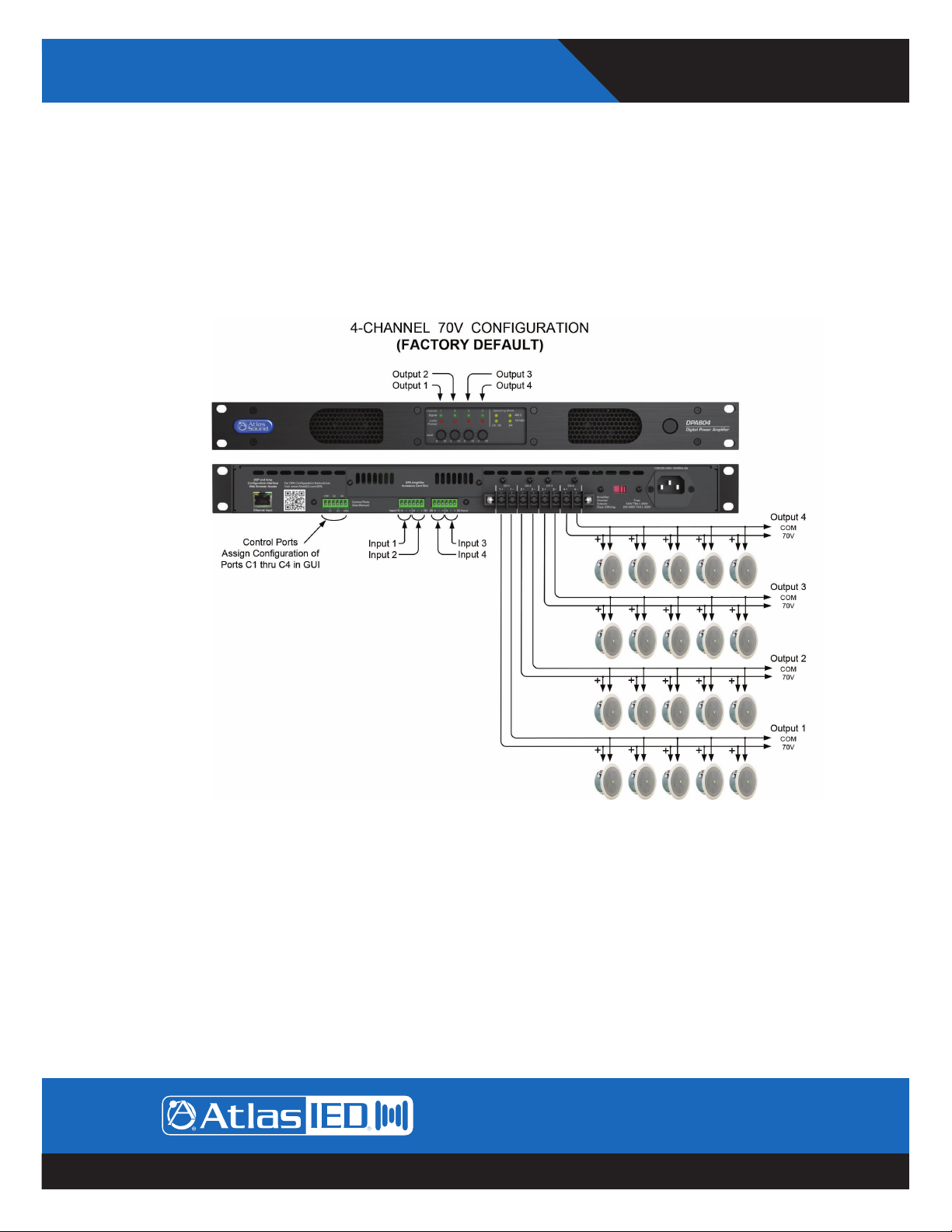
Configuration #1 4-Channel 70V / 100V (Factory Default)
1601 Jack McKay Blvd. • Ennis, Texas 75119 U.S.A.
Telephone: 800.876.3333 • Fax: 800.765.3435
AtlasIED.com – 6 –
Specifications are subject to change without notice.
Owner’s Manual
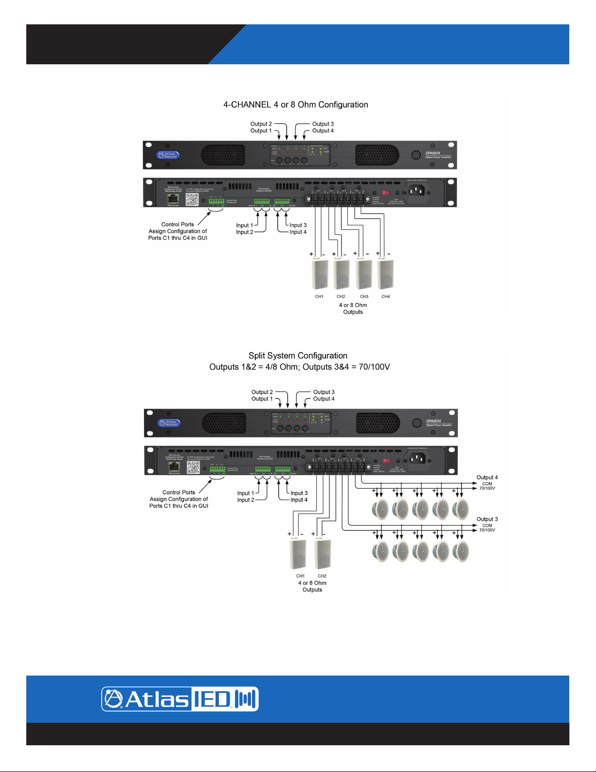
Configuration #2 4-Channel 4 Ohm / 8 Ohm
DPA Series
Digital Power Amplifiers
Configuration #3 2-Channel 70V / 100V & 2-Channel 4 Ohm / 8 Ohm
1601 Jack McKay Blvd. • Ennis, Texas 75119 U.S.A.
Telephone: 800.876.3333 • Fax: 800.765.3435
– 7 – AtlasIED.com
Specifications are subject to change without notice.
DPA Series
Digital Power Amplifiers
Owner’s Manual
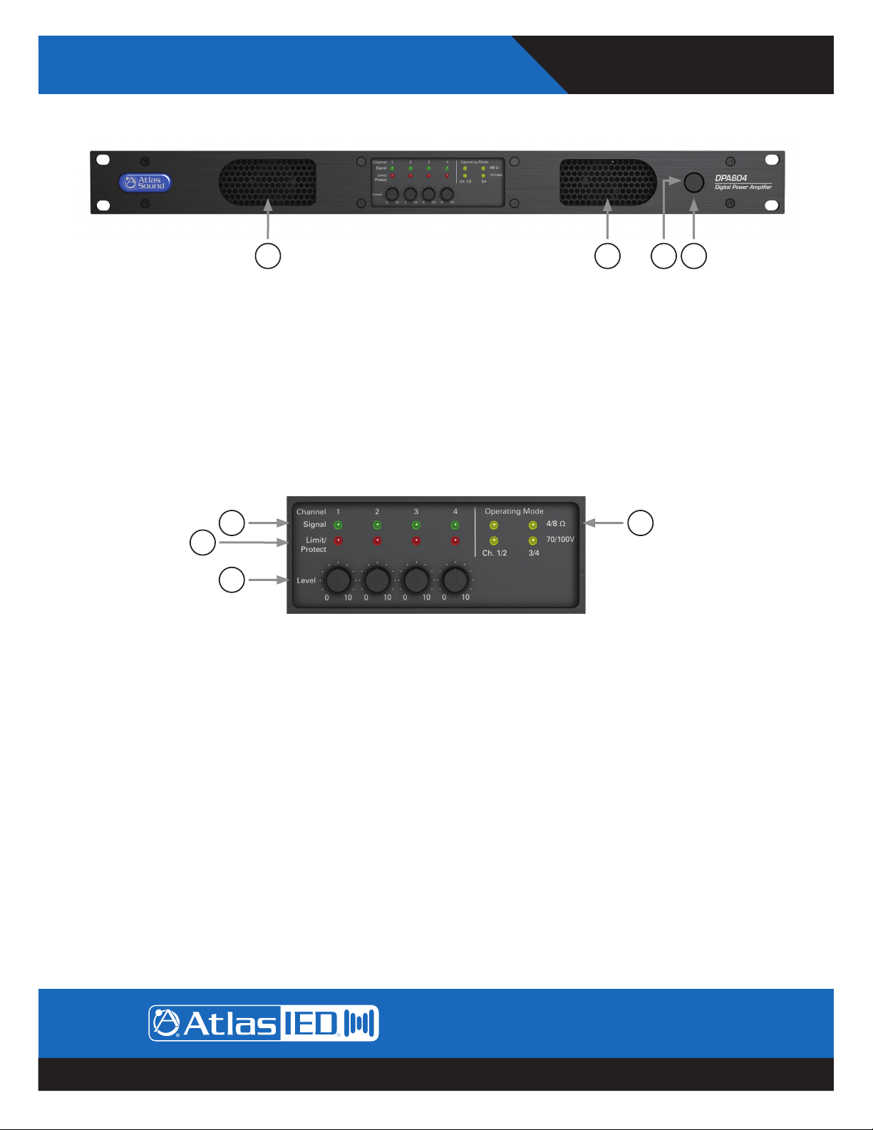
Front Panel
1277
1. Power Switch
This toggles the amplifier between Active Mode or Sleep Mode. Refer to section “Understanding the 3 Amplifier Idle States”.
2. LED Power Indicator
The DPA amplifier has three states of Idle power that are indicated as follows:
A. Idle Active Mode - When the LED outer ring of the power switch illuminates a steady blue color, the amplifier is in Active Mode
and is ready to pass audio.
B. Sleep Mode - When the outer ring LED is Off, the amp is in Sleep Mode. In Sleep Mode, the Ethernet is active for access to the
amplifiers on board GUI. The amplifier output stage and DSP is off. Audio will not pass in Sleep Mode.
C. Standby APD Mode - When the amplifier Auto Power Down (APD) is enabled and the amplifier is in the APD mode, the LED
outer ring will blink blue once every 5 seconds.
For further information refer to section “Understanding the 3 Amplifier Idle States” on page 35.
34
5
6
3. Operating Mode Indicators
The DPA four-channel amplifiers can be configured three ways. The LEDs in this area indicate the configuration of the amplifier. These
indicators illustrate if Channels 1/2 and 3/4 can be operated separately in 4/8Ω mode or 70V / 100V mode. Amplifier operation mode
setting is completed using the internal DSP GUI.
A. 4-Channel High impedance 70V / 100V mode
B. 4-Channel Low impedance 4Ω or 8Ω mode
C. 2-Channel High impedance 70V / 100V mode & 2-Channel Low impedance 4/8Ω mode
4. Channel 1, 2, 3, 4 Signal LED
The Signal LED will illuminate green if audio signal is present at the Output of the amplifier.
5. Channel 1, 2, 3, 4 Limit/Protect/Mute LED
The Limit / Protect LEDs will illuminate Red if one of the following conditions occurs.
A. Any channel of the DPA amplifier reaches maximum output power. The DPA features an adjustable amplifier OUTPUT limiter
which helps prevent the amplifier from hard clipping. An occasional flash of the LED is OK but if the LED illuminates
continuously reduce the input level of the amp. If the Clip LED remains On after reducing the input level, recheck the load
connected to the amplifier.
B. The OUTPUT has been Muted in the GUI.
C. A fault is detected within the amplifier. Once the fault is corrected, it may be required to reset the AC Mains power to reset the
amplifier protect mode.
1601 Jack McKay Blvd. • Ennis, Texas 75119 U.S.A.
Telephone: 800.876.3333 • Fax: 800.765.3435
AtlasIED.com – 8 –
Specifications are subject to change without notice.
Owner’s Manual
DPA Series
Digital Power Amplifiers
Front Panel
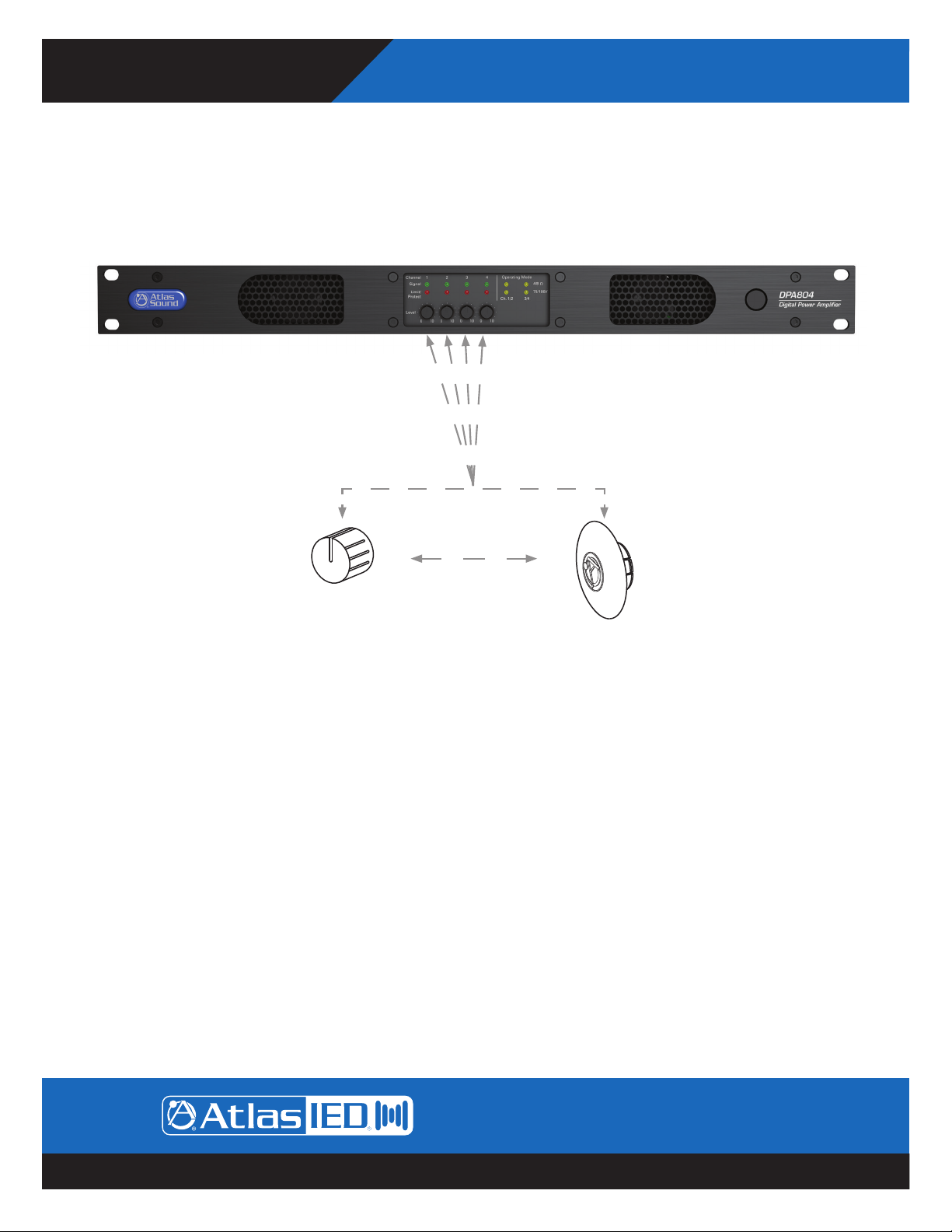
6. Channel 1, 2, 3, 4 Level Controls
Each model has four potentiometer level controls on the front panel, one level control for each of the four amplifier channels. Each
model is shipped factory pre-configured for 4-CH 70V / 100V mode. Note: The front panel level controls ship enabled but can be
defeated in the DSP GUI. If the front panel level controls are used, knobs can be placed on the potentiometer shaft for ease of
operation or can be removed and replaced with the included security covers to prevent tampering.
or
Front Panel
Knob
Security Cover
7. Air Exhaust
Each model includes convection cooling with dynamic fan assist for extreme conditions. If the unit is not being used or in Standby
mode, the fan is not needed for cooling and remains Off until the unit is in heavy use. As heat is generated in the amplifier during use,
the fan activates at a low speed and increases as needed to keep the amplifier at safe operating temperature. This cooling method
eliminates the need for air filters that can become clogged and require maintenance. The DPA amplifier’s air flow is from rear to front.
1601 Jack McKay Blvd. • Ennis, Texas 75119 U.S.A.
Telephone: 800.876.3333 • Fax: 800.765.3435
– 9 – AtlasIED.com
Specifications are subject to change without notice.
DPA Series
Digital Power Amplifiers
Owner’s Manual
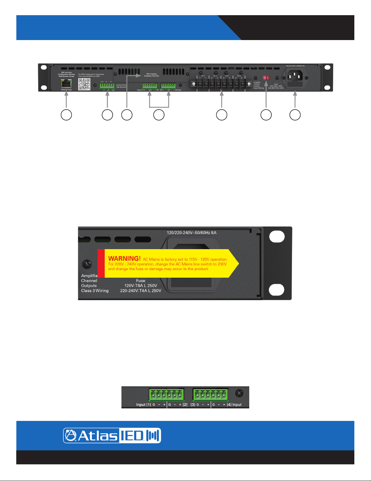
Rear Panel
1245 6 7 3
1. IEC AC Receptacle
The DPA amplifier can operate from 110V - 120V (115V AC Mains Line Selection) & 220V - 240V (230V AC Mains Line Selection). Use
the external switch for AC Mains voltage change over. Note: The DPA404 & DPA804 use different fuses for 115V or 230V operation and
will need to be changed by a qualified technician. The 230V fuses are included within the amplifier packaging. The included IEC cord is
designed to work with 110 - 120VAC. A separate IEC cord will need to be purchased for 220 - 240VAC operation.
The AC Mains fuse is located inside the IEC AC receptacle. A small tool is required to pry oped the Fuse Holder housing. Do not force.
Changing the fuse is required to operate from 220V - 240V. Refer to Page 34 for converting the AC Mains from 120V to 230V operation.
Note: Changing the fuse must be completed by a qualified technician.
• DPA404 120V line voltage operation: T4AL 250V, Slow Blown, 5mm x 20mm, Glass
• DPA404 230V line voltage operation: T2AL 250V, Slow Blown, 5mm x 20mm, Glass
• DPA804 120V line voltage operation: T8AL 250V, Slow Blown, 5mm x 20mm, Glass
• DPA804 230V line voltage operation: T4AL 250V, Slow Blown, 5mm x 20mm, Glass
2. AC Mains Line Voltage Select Switch
The DPA amplifier comes configured to the 115V setting. This setting can be used with AC Mains between 110V - 120V. If 220V - 240V
operation is required, the Line Voltage Select Switch and fuse need to changed. Refer to Page 34 for instructions.
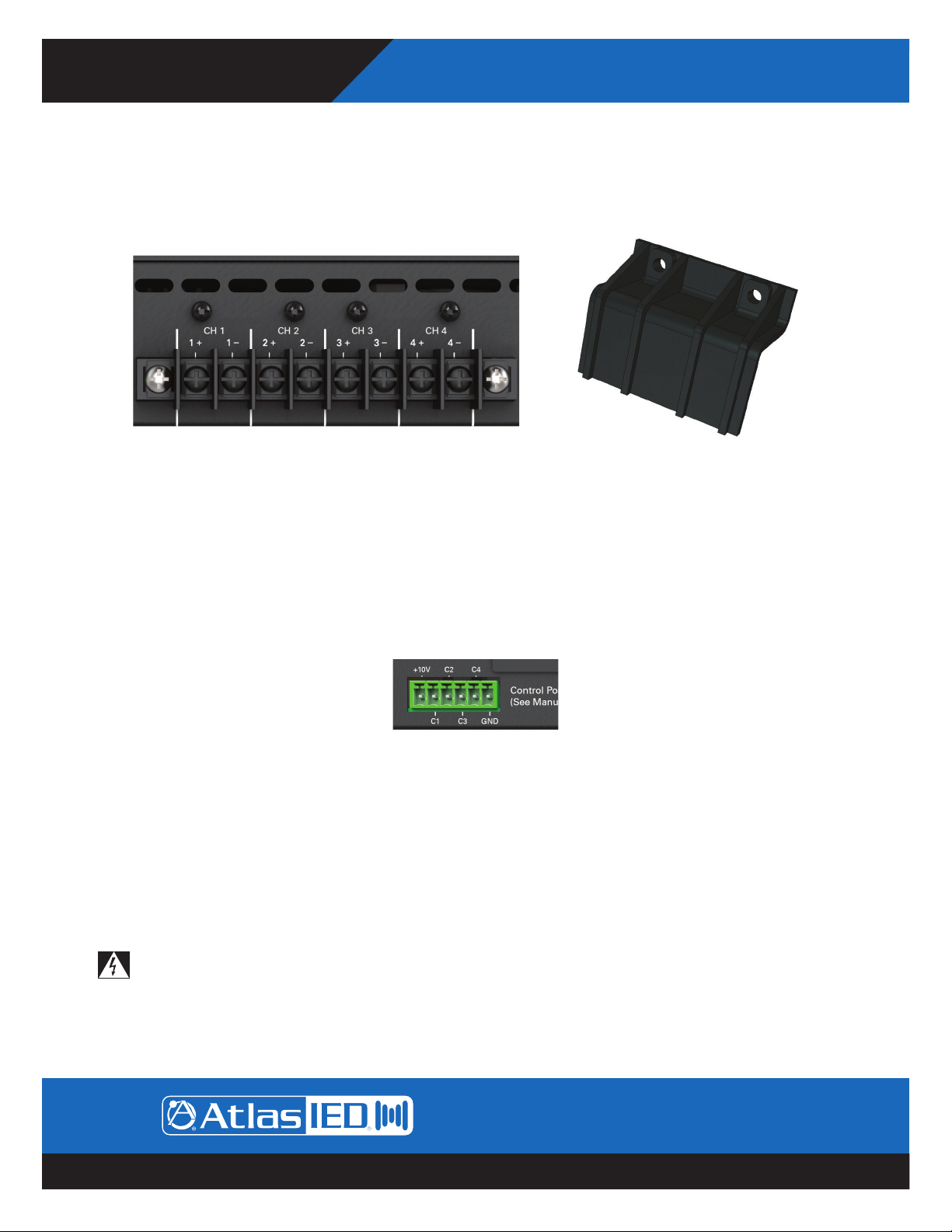
3. Input Connections
Inputs 1 - 4 accept balanced input signals via the removable 3.5mm Phoenix type connector. For wiring follow the labeling on the rear
of the amp. For unbalanced signals connect the (–) and (GND) pins together.
Note: Amplifier Configuration and I/O Routing are done in the GUI. Any Input can be routed to any Output. The DPA is factory shipped
preconfigured in a four-channel 70V / 100V mode. The I/O Router is configured as follows: Input I is routed to Output 1, Input 2 is
routed to Output 2, Input 3 is routed to Output 3, and Input 4 is routed to Output 4.
1601 Jack McKay Blvd. • Ennis, Texas 75119 U.S.A.
Telephone: 800.876.3333 • Fax: 800.765.3435
AtlasIED.com – 10 –
Specifications are subject to change without notice.
Owner’s Manual
DPA Series
Digital Power Amplifiers
4. Speaker Connection
A screw terminal block connector is supplied to connect speakers to the DPA amplifier. It is recommended to use Class 3 rated,
14-gauge wire or lower for speaker wiring. Amplifier output channel configurations are done in the amplifier GUI. The DPA is shipped
with two speaker output terminal covers. AtlasIED recommends placing the security covers on the amplifier after wiring and before
turning the amplifier on for configuration. Included in the carton are 8 (QTY) spade crimp terminals that accept up to 12-gauge wire and
4 (QTY) security cover screws (M3 x 8mm). Terminal block screws are M4.
Note: The DPA amp is preconfigured at the factory for four-channel 70V / 100V mode. Follow the manual wiring information to connect
the distributed audio system.
5. Ethernet Port
Connect the amplifier to the network, local computer, or router/switch using CAT5 cable to access the amplifier’s DSP and control
settings.
6. Control Ports
The DPA Series allows you to assign / configure the four control ports located on the rear of the amplifier to perform Remote Level or
Mute functions. Note: Each Control Port pin can only be assigned to one function such as Mute or Level, but not both. Control Port
assignment is done in the DPA GUI “Mute, Link, Port Assignment Page”. See page 20 for details on how to connect / assign a Remote
Level and a Contact Closure Mute. Note: The factory default assignments for the DPA Amplifier Control Ports are as follows:
Control Port Factory Default Settings (Refer to Remote Level Control)
• C1 Controls CH 1 Output Remote Level
• C2 Controls CH 2 Output Remote Level
• C3 Controls CH 3 Output Remote Level
• C4 Controls CH 4 Output Remote Level
7. Accessory Card Slot
The DPA404 and DPA804 offer 4 additional inputs that can be routed to any of the four output channels. Optional accessory cards
DPA-DAC4 (Four-Channel Dante™ Digital Audio Input Card) and DPA-AMIX (Four-Channel Analog Mic / Line, Auxiliary Input Card) are
available. Contact AtlasIED for a list of accessory cards. See section “Accessory Card Installation” on Page 32 for information on
installation or damage may occur. Note: Accessory card installation must be done by a qualified technician.
Note: In standby mode there are DC voltages present at the accessory card port. The DPA amp must be removed from the AC Mains
source in order to prevent damage to the card or amplifier.
1601 Jack McKay Blvd. • Ennis, Texas 75119 U.S.A.
Telephone: 800.876.3333 • Fax: 800.765.3435
– 11 – AtlasIED.com
Specifications are subject to change without notice.
DPA Series
Digital Power Amplifiers
Owner’s Manual
Accessing the GUI Control Panel
DPA amplifiers include a unique set of features and configurations. All DPA amplifiers are configured from the factory out of the box
to operate as traditional commercial power amplifiers. Ethernet connectivity is not required for operation of a DPA amplifier. However,
to take full advantage of the DSP settings such as, EQ, High & Low Cut filters, level control / assignment and limiter settings, the DPA
Control Panel must be accessed via the network or local computer. External software is not required to operate the DPA amplifier; the
software is embedded in the amplifier in what is called the web browser GUI Control Panel interface. To access the onboard control
panel, follow one of the five methods listed below.
Accessing the GUI Control Panel
I. Direct Connection via Ethernet
II. Web Browser via Network Router
III. AtlasIED DPA Site Manager Software
IV. Smartphone or Tablet
V. Accessing the DPA Outside the Local Network
I. Direct Connection via Ethernet
Use this method if there is no network access available.
1. Connect an Ethernet cable from a laptop or desktop computer to the Ethernet Input on the DPA amplifier. Most computers will
allow direct connection from the DPA amplifier using a standard CAT5 cable. Some older computers may require the use of a
Crossover cable to connect to the DPA amplifier. If a connection cannot be made using a CAT5 cable, use a Crossover cable.
2. Turn OFF the computer’s Wi-Fi.
3. Open a Web browser, AtlasIED suggests using Google Chrome or Mozilla Firefox.
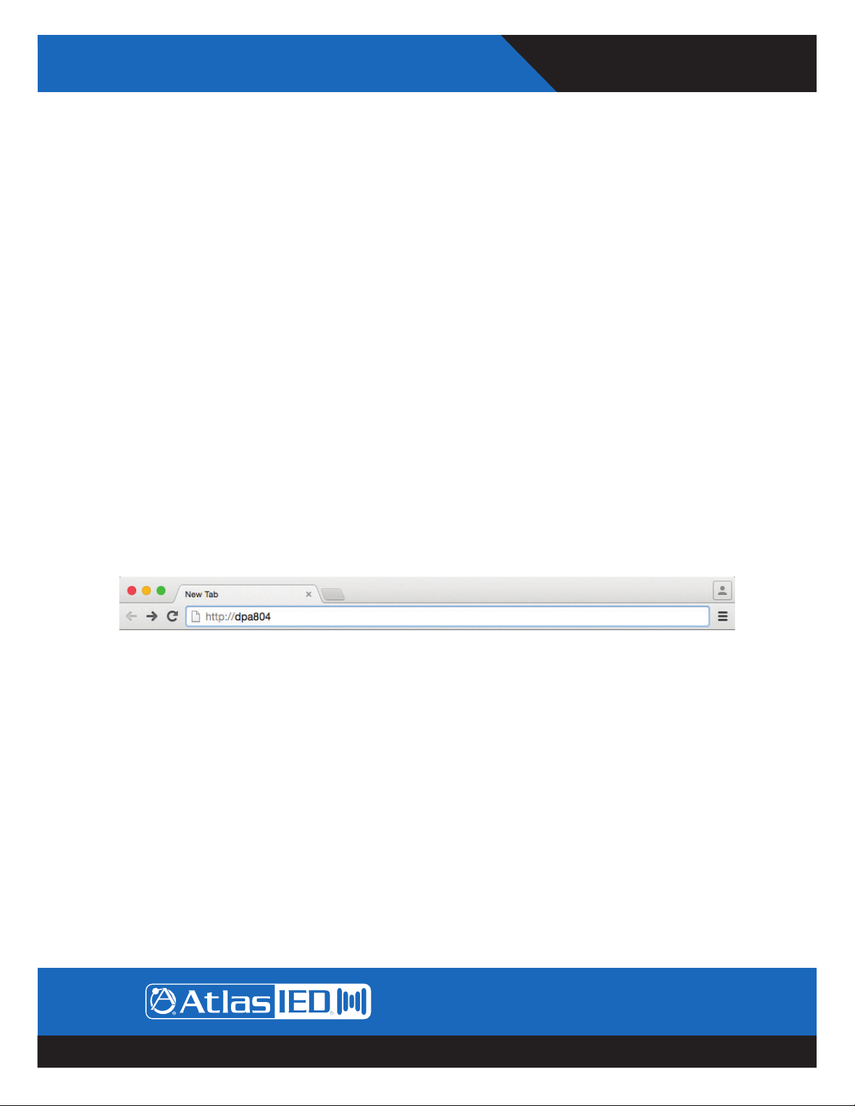
4. In the Web Browser address bar, type in the following: http://DPA804 and hit enter. For this example we are connecting to the DPA
model DPA804. An example is shown in Figure 1.
Figure 1
5. Out of the box the amplifier’s model number is all that is needed to connect. It is not case sensitive, but the full exact name is
required. Note: During configuration, the amplifier’s name can be changed. As an example at a school the amp may be renamed
“ROOM1”. After the name is changed, follow the same process to log onto the amp as outlined above, but change the name from
“http://dpa804” to “http://room1”.
6. The amplifier will be discovered and the DPA User PC Control Page will launch after pressing the “Enter” key. An example of the
DPA User PC Control Page GUI web page is shown in Figure 2.
7. The DPA amplifier’s IP address can be directly entered into the Web Browser to access the DPA GUI.
Example: “http://192.168.1.110”.
Note: It is required to enter the Administrator Name and Password to access the home page. Factory default for User Name is
“admin” and the password is “admin”.
Note: When on the Mobile Page, on the Setup page, the faders will not function. To make setting changes the value of change
must be entered in the data box. In the amp configure page the Level faders can be linked together for stereo level adjustment.
1601 Jack McKay Blvd. • Ennis, Texas 75119 U.S.A.
Telephone: 800.876.3333 • Fax: 800.765.3435
AtlasIED.com – 12 –
Specifications are subject to change without notice.
 Loading...