

Page 1
Install Instructions
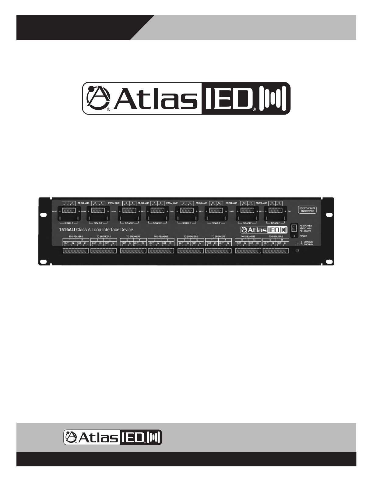
1516ALI & 1516BLI
Class A/B Loop Interface
1516ALI & 1516BLI
Class A/B Loop Interface
DOC1241B
9701 Taylorsville Rd. • Louisville, KY 40299 U.S.A.
Telephone: 502.267.7436 • Fax: 502.267.9070
– 1 – AtlasIED.com
Specifications are subject to change without notice.
Page 2

1516ALI & 1516BLI
Class A/B Loop Interface
Install Instructions
Table of Contents
Important Safety Instructions .................................................................................................................. 3
Introduction ............................................................................................................................................ 9
1516ALI Installation ............................................................................................................................... 11
Connecting Multiple Loops To One Amplifier Channel ......................................................................... 13
1516ALI Initial Configuration ................................................................................................................ 14
Add 1516ALI To GLOBALCOM®.IP System .......................................................................................... 16
Device Recovery................................................................................................................................... 18
FCC & Legal Notices ............................................................................................................................. 19
Warranty ................................................................................................................................................ 20
9701 Taylorsville Rd. • Louisville, KY 40299 U.S.A.
Telephone: 502.267.7436 • Fax: 502.267.9070
AtlasIED.com – 2 –
Specifications are subject to change without notice.
Page 3
Install Instructions
1516ALI & 1516BLI
Class A/B Loop Interface
Important Safety Instructions
The lightning flash with arrowhead symbol within an equilateral triangle,
is intended to alert the user to the presence of uninsulated “dangerous
voltage “ within the product’s enclosure that may be of sufficient
magnitude to constitute a risk of electric shock to persons.
WARNING: SHOCK HAZARD - DO NOT OPEN
AVIS: RISQUE DE CHOC ELÉCTRIQUE - NE PAS OUVRIR
WARNING: TO REDUCE THE RISK OF FIRE OR ELECTRIC SHOCK
DO NOT EXPOSE THIS EQUIPMENT TO RAIN OR MOISTURE
AVIS: NE PAS EXPOSER CE MATÉRIEL À LA PLUIE OU L’HUMIDITE
AFIN DE REDUIRE LE RISQUE D’INFLAMMATION OU DE CHOC ELÉCTRIQUE
1. Read these instructions.
2. Keep these instructions.
3. Heed all warnings.
4. Follow all instructions.
5. Do not use this device near water.
6. Clean only with dry cloth.
7. Do not block any ventilation openings. Install in accordance with the manufacturer’s instructions.
8. Do not install near any heat sources such as radiators, heat registers, stoves, or other device that produce heat.
9. Do not defeat the safety purpose of the polarized or grounding-type plug. A polarized plug has two blades with one wider than the
other. A grounding type plug has two blades and a third grounding prong. The wide blade or the third prong are provided for your
safety. If the provided plug does not fit into your outlet, consult an electrician for replacement of the obsolete outlet.
10. Protect the power cord from being walked on or pinched particularly at plugs, convenience receptacles, and the point where they
exit from the device.
11. Only use attachments/accessories specified by the manufacturer.
12. Use only with the cart, stand, tripod, bracket, or table specified by the manufacturer, or sold with the device. When a cart is used,
use caution when moving the cart / device combination to avoid injury from tip-over.
The exclamation point within an equilateral triangle is intended to
alert the user to the presence of important operating and maintenance
(servicing) instructions in the literature accompanying the product.
13. Unplug this device during lightning storms or when unused for long periods of time.
14. Refer all servicing to qualified service personnel. Servicing is required when the device has been damaged in any way, such as
power-supply cord or plug is damaged, liquid has been spilled, or objects have fallen into the device, the device has been exposed
to rain or moisture, does not operate normally, or has been dropped.
15. This product is equipped with a three-wire grounding-type plug, a plug having a third (grounding) pin. This plug will only fit into a
grounding-type power outlet. This is a safety feature. If you are unable to insert the plug into the outlet, contact your electrician to
replace your obsolete outlet. Do not defeat the safety purpose of the grounding-type plug.
16. WARNING: To reduce the risk of fire or electric shock, this device should not be exposed to rain or moisture and objects filled with
liquids, such as a vase, should not be placed on this device.
17. To completely disconnect this equipment from the mains, disconnect the power supply cord plug from the receptacle.
18. The mains plug of the power supply cord shall remain readily operable.
19. Protective earthing terminal. The apparatus should be connected to a mains socket with a protective earthing connection.
9701 Taylorsville Rd. • Louisville, KY 40299 U.S.A.
Telephone: 502.267.7436 • Fax: 502.267.9070
– 3 – AtlasIED.com
Specifications are subject to change without notice.
Page 4
1516ALI & 1516BLI
Class A/B Loop Interface
Install Instructions
WARNING - When The Device Is In Use
• WARNING: For the terminals marked with symbol of may be of sufficient magnitude to constitute a risk of electric shock. The
external wiring connected to the terminals requires installation by an instructed person or the used of ready-made leads or cords.
• WARNING: The apparatus shall not be exposed to dripping or splashing and that objects filled with liquids, such as vases, shall not be
placed on apparatus.
• WARNING: The mains plug is used as disconnect device, the disconnect device shall remain readily operable.
• To prevent electric shock, do not remove the product cover as there are high voltage components inside. Refer all servicing to
AtlasIED.
• Should any of the following irregularities occur during use, immediately switch off the power, disconnect the power cord from the
AC outlet and contact AtlasIED. Do not to attempt to continue operation with the product as this may cause fire or electric shock:
• Smoke or strange smell coming from the unit.
• If the product falls or the case is damaged.
• If water or any metallic objects falls into the product.
• If the power supply cord is damaged in any way.
• If the unit is malfunctioning.
• Do not insert or drop metallic objects or flammable materials into the ventilation holes of the product's cover, as this may result in
electric shock or fire.
• Do not place any containers with liquid or metallic objects on the top of the product. If any liquid spills into the unit, fire or electric
shock may result.
• Never operate this product or touch the power supply cord during an electrical storm, electric shock may result.
• Never exceed the power rating on the product when connecting equipment. Fire and/or property damage may result.
• Operate the product only with the voltage specified on the unit. Fire and/or electric shock may result if a higher voltage is used.
• Do not modify, kink, or cut the power cord. Do not place the power cord in close proximity to heaters and do not place heavy objects
on the power cord, including the product itself, doing so may result in fire or electrical shock.
• Ensure that the safety ground terminal is connected to a proper ground. Never connect the ground to a gas pipe as a catastrophic
disaster may result.
• Be sure the installation of the product is stable, avoid slanted surfaces as the product may fall and cause injury or property damage.
CAUTION - When Installing The Product
• Plugging in or unplugging the power cord with wet hands may result in electric shock.
• Never move the unit with the power cord plugged into the wall, as damage to the power cord may result.
• When unplugging the cord from the wall, grasp the plug, NOT the cord.
• Never install this product in humid or dusty locations, nor in direct sunlight, near sources of heat, or in areas where sooty smoke or
steam are present. Fire and electric shock may result.
• Keep all sides of the unit at least 31/2" away from objects that may obstruct air flow to prevent the unit's internal temperature rise.
CAUTION - When The Product Is In Use
• Never place heavy objects on the product, causing it to fall and/or break, resulting in personal injury and property damage. In
addition, the product itself may fall and cause injury and property damage.
• Contact AtlasIED for instructions on cleaning the inside of the unit. Large accumulations of dust inside the unit may result in heat
buildup and fire.
• Ensure that the power supply plug is securely plugged into the wall outlet. Never allow dust to accumulate on the power plug or
inside the wall outlet.
• When cleaning the unit or the unit is not to be operated for an extended period, unplug the power cord from the wall.
9701 Taylorsville Rd. • Louisville, KY 40299 U.S.A.
Telephone: 502.267.7436 • Fax: 502.267.9070
AtlasIED.com – 4 –
Specifications are subject to change without notice.
Page 5

Install Instructions
WARNING: To reduce the risk of fire or electric shock, do not expose this apparatus to rain, moisture, dripping, splashing, or place
objects filled with liquids on the equipment.
AVERTISSEMENT: Afin de réduire le risque d’incendie ou de choc électrique, n’exposez pas cet appareil à la pluie, à l’humidité, à
l’égouttement, aux éclaboussures, et ne posez pas des objets remplis de liquide sur l’appareil
WARNING: If apparatus is equipped with Class I grounding plugs for safety purposes, it must be connected to MAINS that employ a
protective earth ground connection.
AVERTISSEMENT: si l’appareil est équipé de prises de terre classe I, pour des raisons de sécurité, il doit être branché sur un réseau
ayant une prise de terre de protection.
WARNING: The MAINS plug on this device may be used as the DISCONNECT DEVICE for MAINS power and must remain readily
operable.
AVERTISSEMENT: La prise principale de cet appareil peut être utilisé comme DISPOSITIF de DECONNEXION du courant principal et
doit rester facilement accessible.
WARNING: Installation and maintenance of IED equipment is to be made by trained/qualified personnel and must conform to all
applicable local codes.
AVERTISSEMENT: l’installation et la maintenance des équipements IED doit être faite par du personnel formé / qualifié et doivent être
conformes à toutes les réglementations locales en vigueur.
WARNING: If unit contains a lithium battery, there is a danger of explosion. Replace only with the same or equivalent type.
AVERTISSEMENT: Si l’unité contient une pile au lithium, il y a un danger d’explosion. Remplacez-la uniquement avec un modèle
identique ou équivalent.
1516ALI & 1516BLI
Class A/B Loop Interface
SAFETY CONSIDERATIONS
SAFETY PRECAUTIONS
Personnel properly qualified in the application and use of life safety equipment (“qualified personnel”) shall read this manual carefully
before performing any actions to specify, apply, install, maintain and perform operational tests of IED systems, and associated products
in accordance with the instructions in this manual. This manual shall be made available to all qualified personnel who operate, test,
maintain, or service IED systems, and associated products. It is strongly recommend that such personnel read and understand the
entire manual.
WARNING: IF SAFETY PRECAUTIONS, INSTALLATION AND TESTING ARE NOT PERFORMED PROPERLY, CONDITIONS COULD
EXIST IN WHICH THE IED SYSTEM MAY NOT OPERATE, OR MAY OPERATE IMPROPERLY. THIS COULD RESULT IN PROPERTY
DAMAGE AND SERIOUS INJURY OR DEATH TO YOU AND/OR OTHERS.
AVERTISSEMENT: SI LES MESURES DE SECURITE, L’INSTALLATION ET LES ESSAIS NE SONT PAS EFFECTUES
CORRECTEMENT, CELA POURRAIT EMPECHER LE SYSTÈME IED DE FONCTIONNER, OU DE FONCTIONNER CORRECTEMENT.
CELA POURRAIT PROVOQUER DES DEGATS MATERIELS ET DES BLESSURES GRAVES, OU LA MORT POUR LES AUTRES ET/
OU VOUS-MEMES.
It is very important that only responsible, trained personnel are allowed to operate and maintain these systems, and that they use
only appropriate equipment and tools. If a person is not trained, they shall contact the IED factory for direction on how to operate and
maintain an IED system.
9701 Taylorsville Rd. • Louisville, KY 40299 U.S.A.
Telephone: 502.267.7436 • Fax: 502.267.9070
– 5 – AtlasIED.com
Specifications are subject to change without notice.
Page 6

1516ALI & 1516BLI
Class A/B Loop Interface
Unauthorized personnel and equipment must be restricted from the areas of operation.
All operations should be performed carefully, methodically, and without hurrying. Greater effectiveness will be developed by increased
familiarity of personnel with their assignments. During any maintenance operation, if a malfunction occurs or an incorrect indication
appears, stop the operation and determine whether or not it is safe to proceed. Before performing any step in a procedure, be sure that
the preceding step has been properly executed and correct results obtained. Cleanliness and good housekeeping in all installation areas
are major factors in effective accident prevention. Tools and equipment should be maintained in good working order and should always
be returned to their proper storage place after usage. Cleaning agents and other cleaning aids should be removed from the equipment
areas immediately upon completing the task at hand.
-Changes, modifications, or additions in connection with the IED system equipment shall not be made without explicit authorization of IED.
Safety devices found on mechanical, and electrical and electronic equipment are put there for the protection of personnel and
equipment. These devices must be maintained in good working order and operative at all times. Safety devices shall never be removed
or bypassed unless specifically authorized by the IED factory. Where safety devices have been rendered inoperable by proper and
specific authorization, adequate notices shall be posted to warn personnel of the potential hazard.
Avoid the use of flammable or toxic cleaning fluids, and the use of carbon tetrachloride is prohibited.
Maintenance of the equipment shall be at least what is specified in the IED manuals and literature, and performed only by qualified
personnel.
Install Instructions
Whenever operation and maintenance is ongoing, personnel in the equipment areas shall have an effective communication among
these areas in order to protect people if any accident occurs.
PRELIMINARY PRECAUTIONS
Precautions which are applicable to general electrical or electronic maintenance are as follows:
a. Check yourself. Wear no article that might catch on equipment or that might act as a conductor.
b. Check the working area. The equipment area shall be clean and dry. If possible, stand on a special insulator such as a
rubber mat. There should be ample working space and good lighting.
c. Check the tools. Always use proper tools and check them for their safe condition. Use screwdrivers with plastic handles.
Check test equipment periodically and examine test leads carefully as the slightest break in insulation is dangerous.
d. Check the procedures. Study the entire procedure before taking the first step. Consult the circuit diagram frequently to
obtain an understanding of what is accomplished at each step. Know what is in the equipment and how it differs from
others on which you have worked.
e. Be aware that high voltages may be present across terminals that are normally low voltage, due to equipment
breakdown. Be careful when measuring low voltages in equipment containing high voltage circuits.
f. Do not make resistance measurements with power on.
g. Do not work within the equipment without the presence of a person who is capable of rendering aid, and who is familiar
with the procedure for emergency shutdown of the equipment.
9701 Taylorsville Rd. • Louisville, KY 40299 U.S.A.
Telephone: 502.267.7436 • Fax: 502.267.9070
AtlasIED.com – 6 –
Specifications are subject to change without notice.
Page 7

Install Instructions
PRECAUTIONS WHEN MEASURING HIGH VOLTAGE POTENTIALS
Observe the following precautions when measurements must be performed on circuits with potentials over 48 volts.
h. Do not measure potentials over 48 volts without the presence or assistance of a person who is capable of rendering aid,
and who is familiar with the procedure for emergency shutdown of the equipment.
i. Be sure you are not grounded when you are adjusting equipment or using measuring equipment. Stand on a rubber mat
or other insulator if possible. Be sure the equipment area is clean and dry. In general, use only one hand when servicing
live equipment.
j. If a test meter must be held or adjusted while voltage is applied, ground the case of the meter before starting a
measurement. Do not touch the live equipment or personnel working on live equipment while holding the meter. The
“common” terminal on some A/C electronic voltmeters is at ground potential; never connect the “common” terminal to
any point above ground potential.
k. High-voltage, high-capacitance capacitors should be discharged before servicing is started.
WARNING! Discharging must be done carefully and judiciously. First ascertain whether there is a built-in bleeder
network. If so, wait a minute or two for the capacitor to discharge through the network. Otherwise, use an external
discharge network. This is most important in the case of high voltage or high capacitance capacitors. If one terminal
is connected to ground, connect the discharge network between the other terminal and ground. If neither terminal
of the capacitor is grounded, connect the network across the capacitor terminals. Connecting a short circuit across
the terminals is not recommended. Doing so can produce extremely high currents and a flash which can injure the
eyes, vaporize metals, and cause burns.
1516ALI & 1516BLI
Class A/B Loop Interface
AVERTISSEMENT: La décharge doit être faite soigneusement et judicieusement. Vérifier d’abord si il y a un réseau
de purgeur incorporé. Si c’est le cas, attendez une minute ou deux pour que le condensateur se décharge par le
réseau. Sinon, utilisez un réseau de décharge externe. Ceci est très important en cas de haute tension ou des
condensateurs à haute capacité. Si un terminal est relié à la terre, connecter le réseau de décharge entre l’autre
terminal et la terre. Si aucun terminal de condensateur est fondé, relier le réseau au terminal du condensateur. La
connexion d’un court-circuit entre les terminaux n’est pas recommandée. Cela peut créé des courants très élevés
où des étincelles pourrait blesser les yeux, fondre les métaux et causer des brûlures.
9701 Taylorsville Rd. • Louisville, KY 40299 U.S.A.
Telephone: 502.267.7436 • Fax: 502.267.9070
– 7 – AtlasIED.com
Specifications are subject to change without notice.
Page 8

1516ALI & 1516BLI
Class A/B Loop Interface
PRECAUTIONS WHEN WORKING ON ENERGIZED EQUIPMENT
When it is necessary to work on energized equipment, think ahead and anticipate every hazard. Never work alone on energized
equipment.
Interlock switches are installed on some of the doors and panels to break the power circuits when the enclosure is entered. When it is
necessary to work within such an enclosure on energized equipment, the interlock may be bypassed. Extreme caution should then be
exercised, as dangerous voltages are present within the unit.
AC POWER CIRCUITS
Equipment obtaining power from a secondary distribution system should be grounded at all times by means of a third grounding
wire on the power lines. Equipment permanently wired to a secondary distribution system should also be grounded separately by
connection to a grounding bus or ground rod with a sufficiently large conductor to handle the current expected if the secondary source
is accidentally shorted to the equipment.
The ground wire should be protected from mechanical damage and periodically inspected for good physical condition.
Personnel should never depend on a switch to remove power from equipment. If the equipment is connected to the secondary
distribution system by means of a power cable, detach the cable from the receptacle before attempting any repairs of removal of
chassis.
Install Instructions
If the equipment is permanently wired to the secondary distribution system, remove the main fuses or open the power switch. Attach
a suitable warning tag to the switch which will warn personnel not to operate the equipment; only the person who originally attaches
the warning tag should be authorized to remove it.
RESUSCITATION
Personnel working with or near high voltage should be familiar with modern methods of resuscitation. Such information and training is
available from the Red Cross or local emergency response personnel such as the police and fire department.
9701 Taylorsville Rd. • Louisville, KY 40299 U.S.A.
Telephone: 502.267.7436 • Fax: 502.267.9070
AtlasIED.com – 8 –
Specifications are subject to change without notice.
Page 9

Install Instructions
1516ALI & 1516BLI
Class A/B Loop Interface
Introduction
The 1516ALI (or 1516BLI) is a device that provides Class A (or Class B) speaker loop wiring support and supervision between an IED
integrated amplifier system such as the Titan T9160, T112 or DNA2404C/D, and looped speaker field wiring. This device provides several
functions:
• Provides connections for both the “outbound” and return or “inbound” portion of the speaker loop.
• Supervises the loop and indicates a fault when the loop is broken*
• Delivers audio on both branches of the loop to provide failsafe operation after a loop is broken (1516ALI only).
The 1516ALI (1516BLI) provides interfaces for up to 16 Class A (Class B) speaker loops. Typically this represents 16 amplifier channels,
but it is possible to wire one amplifier channel to drive more than one speaker loop, if that is how the facility wiring is arranged and
the load presented by the multiple loops are compatible with the amplifier’s capacity. Loop faults are indicated via yellow LEDs on
the 1516ALI/1516BLI unit and are reported over the network to an AtlasIED GLOBALCOM® system. Faults can be disabled via 2-pin
jumpers on unused loop interfaces.
The 1516ALI/1516BLI can be entirely powered over the network via power over Ethernet (IEEE 802.3af compliant PoE). Or, if PoE is not
available, the unit may be powered from an external 48V supply. Since, externally/physically the 1516ALI and 1516BLI are identical the
descriptions which follow will only show/discuss the one product, the 1516ALI, for simplicity.
* Special Note: In order to detect a break in either wire of a loop, it is necessary to install speakers with DC blocking capacitors.
Without such speakers/capacitors, the 1516ALI/1516BLI can only detect a fault when the whole loop cable is severed.
9701 Taylorsville Rd. • Louisville, KY 40299 U.S.A.
Telephone: 502.267.7436 • Fax: 502.267.9070
– 9 – AtlasIED.com
Specifications are subject to change without notice.
Page 10

1516ALI & 1516BLI
Class A/B Loop Interface
Install Instructions
1
3
2
4
Figure 1: 1516ALI Front View
5
6
7
8
1. Connection from Amplifiers
Two amplifier channels in one 4-pin removable connector.
2. Connection to Speaker Loops
Two speaker loops/channels in one 8-pin removable connector.
Note, there are outbound and inbound connections for each speaker loop.
3. Fault LEDs (yellow)
One LED per channel/loop. This reflects what is also reported via the network.
4. Fault Disable Jumpers
One jumper per channel/loop. Placing a jumper on the pins disables fault reporting for this channel/loop.
These should be applied to any unused channels on the 1516ALI and to any speaker lines not wired as a loop.
5. Auxiliary Power Input
As an alternate to Power Over Ethernet (PoE), 48V DC power may be supplied here to power the device.
6. Power LED (green)
7. Ground Connection
Must be tied to chassis ground of the power amps (or earth).
8. Ethernet Connection
If PoE power compliant with IEEE 802.3af is available, it can be used to power the device.
Figure 2: 1516ALI Front View
9701 Taylorsville Rd. • Louisville, KY 40299 U.S.A.
Telephone: 502.267.7436 • Fax: 502.267.9070
AtlasIED.com – 10 –
Specifications are subject to change without notice.
Page 11

Install Instructions
1516ALI & 1516BLI
Class A/B Loop Interface
1516ALI Installation
Unpacking And Preparing The Unit
Unpack the unit from its shipping carton and identify any accompanying components that may have been included. The unit comes with
rack ears for easy mounting into a 19” rack.
Install Unit Into A Rack
The ideal location for mounting the 1516ALI is on rear rack rails, typically right behind the AtlasIED amplifier units to which they will
connect. Alternately, they may be placed on rails near the speaker field wiring terminal blocks in the rack.
Make Ground Connection
If there is a solid connection to ground via the rack ears and screws, then this step is optional. For good measure, though, one should
be sure to provide a solid ground connection to the ground connector on the 1516ALI case (7). This connection is necessary for the fault
detection function.
The amplifier outputs have a Voltage on them relative to ground. The detection circuitry requires a solid ground reference in
order measure this voltage and properly function.
Connect Amplifier Wiring
Connections should be made to the amplifier input terminals (1) being sure to observe the polarity markings on the connections.
Connect Speaker Loop Wiring
It is critical that speaker loop connections are made correctly to prevent serious damage to the amplifiers. Incorrectly connected
loops can create SHORT CIRCUITS across the amplifier outputs. Please read and understand this section, and observe it in
making the speaker loop connections, before applying power to the amplifiers connected to the 1516ALI.
It is important that a speaker loop strictly observes polarity all along its path so that the plus (+) connection going out is the same as
the plus (+) connection coming back in, and the same on the minus side. This may be done simply by always connecting the same color
wire all along the way, e.g., black-to-black and white-to-white. If one is unsure of how the field wiring was done, then the lines should
be tested a cross-over in polarity.
Unfortunately, it is not possible to detect a cross-over in the wiring with a simple Ohmmeter. That is because these utilize DC Voltages,
and at DC, both lines appear to be shorted together. This is because the coils in the speaker transformers appear as “just wire” to DC
voltages, and these coils are connected across the speaker lines. So the testing must be done with an AC drive voltage.
The AC line test procedure one can employ is as follows:
• Disconnect both the + and – wires of the IN connection for a speaker loop, leaving only the OUT connection attached.
• If one has an impedance meter, which drives a line with an AC tone, this can be connected to the Amplifier Input for the loop being
tested. Otherwise, power up the amplifier driving this loop and apply a test tone to it (e.g., using the Circuit Test feature in System
Manager Center).
• Attach a Voltmeter set for AC reading between the + OUTbound connection and the + INbound wire (not yet inserted into the
1516ALI).
• If the polarity is correct, one should observe NO VOLTAGE between these points. If incorrect, then one will see a voltage.
One should make the IN connections on the 1516ALI in accordance with the test, even if it does involve a “flip” in wiring color. This just
means an odd number of such flips were made in the field wiring.
9701 Taylorsville Rd. • Louisville, KY 40299 U.S.A.
Telephone: 502.267.7436 • Fax: 502.267.9070
– 11 – AtlasIED.com
Specifications are subject to change without notice.
Page 12

1516ALI & 1516BLI
Class A/B Loop Interface
Install Instructions
Figure 3: Testing a Speaker Loop
9701 Taylorsville Rd. • Louisville, KY 40299 U.S.A.
Telephone: 502.267.7436 • Fax: 502.267.9070
AtlasIED.com – 12 –
Specifications are subject to change without notice.
Page 13

Install Instructions
1516ALI & 1516BLI
Class A/B Loop Interface
Connecting Multiple Loops To One Amplifier Channel
If there are multiple speaker lines (loops) that “homerun” to the equipment room to be driven by one amplifier channel, these can be
accommodated by the 1516ALI with proper wiring, so long as the total load presented is not over the amplifier’s rating (e.g., two loops
of 100 Watt load each on a 200 Watt amplifier channel). This is done, simply by daisy-chaining the amplifier input wiring on the Amp In
connectors of the 1516ALI as shown in the figure below.
Figure 4: Connecting Multiple Loops to One Amplifier Channel
Install Bypass Jumpers
For any channels not connected to Class A loops, install a bypass jumper into the Fault Bypass pins (4) at that position.
Connect To Network
Connect the 1516ALI to the network via the RJ-45 connector on the rear. If PoE power is available, the power LED (6), should illuminate
after a couple of seconds.
(Opt.) Connect Auxiliary 48V Power
If the network does not supply PoE power, then the device should be powered from a separate 48V DC supply connected to the
Auxiliary Power Input jack (5).
9701 Taylorsville Rd. • Louisville, KY 40299 U.S.A.
Telephone: 502.267.7436 • Fax: 502.267.9070
– 13 – AtlasIED.com
Specifications are subject to change without notice.
Page 14

1516ALI & 1516BLI
Class A/B Loop Interface
Install Instructions
1516ALI Initial Configuration
From the factory, the 1516ALI comes with a fixed address of 10.2.150.182. These settings can be changed as necessary via the built-in
web pages. One accesses the web pages by typing the IP address into a browser address bar, e.g., “http://10.2.150.182”.
Note, one will need to be on a computer configured to be on a compatible 10.x.y.z network in order to access the device at this
address. This may require one to (temporarily) add a compatible network setting on their laptop or desktop computer used to access
these web pages.
The first page one encounters is the Status page. This shows the current state of all of the loops. One wants to click on the “Settings”
label on the left (circled in red in the figure below) to go to the Settings page.
Figure 5: 1516ALI Status Web Page
Before accessing the Settings page, one must enter the current password in the edit box shown below. By default from the factory, the
password is “iednet” (without the quotes). This password can be changed on the Settings page, once accessed, if desired.
Figure 6: 1516ALI Settings Authorization
9701 Taylorsville Rd. • Louisville, KY 40299 U.S.A.
Telephone: 502.267.7436 • Fax: 502.267.9070
AtlasIED.com – 14 –
Specifications are subject to change without notice.
Page 15

Install Instructions
Once the correct password is entered and the Enter button pressed, one is taken to the Settings page as shown in the example below.
1516ALI & 1516BLI
Class A/B Loop Interface
Figure 7: 1516ALI Setting Page
On this page, one can either enter the proper fixed address settings (IP address, subnet mask, and router or default gateway) or
alternately enable DHCP (dynamic addressing) via the checkbox provided. This is also where one can optionally build in an address to
always report faults to (e.g., a controller). The Password edit box is where one can change the password used to access the Settings
page. One must click on the “Save Settings” button in order for the changes to take effect.
Once all the changes are made, one presses the Save Settings button. After the settings are saved to flash, they will not take effect
until the unit is rebooted or re-powered. When changes are made and saved, the web page will prompt to reset the device via the
button and red notification shown in the figure below.
Figure 8: Prompt Reset
9701 Taylorsville Rd. • Louisville, KY 40299 U.S.A.
Telephone: 502.267.7436 • Fax: 502.267.9070
– 15 – AtlasIED.com
Specifications are subject to change without notice.
Page 16

1516ALI & 1516BLI
Class A/B Loop Interface
After pressing the Reset button, one gets the web page shown below. Note, if the IP address is changed, the link to the web pages
will break. The new IP address will have to be entered into the browser address bar.
Figure 9: Reset Notification
Install Instructions
Add 1516ALI To GLOBALCOM.IP System
Once the unit is powered up and connected to the network, it should be added to the GLOBALCOM®.IP system it is a part of via the
System Management Center (SMC). The process for doing this is detailed below.
Add the Device to the System
The 1516ALI is not added as a special device type, but as an
“External Supervised Device” that can pass fault information
via IEDnet. This is done by adding a device of this type via the
following steps.
• Go to the Configuration tab page
• Select the Devices section
• Click on the [+] button at the top to add a device
• Under Third-Party Devices, locate the row for “External
Supervised Device” and fill in a quantity (1 or more) of these
devices to add a this time (see screen shot at right)
• Tab or click out of the quantity (# Devices) field to enable
the OK button
• Click on the OK button
• Double-click on each newly added device and fill in its basic
information such as the example shown below. At a minimum,
one should:
• Enter a Description for the unit
• Set the IP Address field to the device’s network address.
• Set the Supervision Method field to “IEDnet”
The Location field is totally optional, providing a place to record
other project-related information on this device. The Supervision
Details field is not used for this device.
9701 Taylorsville Rd. • Louisville, KY 40299 U.S.A.
Telephone: 502.267.7436 • Fax: 502.267.9070
AtlasIED.com – 16 –
Specifications are subject to change without notice.
Page 17

Install Instructions
Define Faults for the Device
With the device added to the system, any time breaks in the supervised loops are detected, they will be reported in SMC such as
shown in the screen shot below. Faults reported by these devices are all Fault Type 40, with Fault Numbers going from 1 to 16 to
represent loops 1 to 16. The default descriptions as shown below consist of the device description followed by the fault numbers 40/x.
In the example, both loops 15 and 16 are faulted for the newly added frame.
1516ALI & 1516BLI
Class A/B Loop Interface
The fault descriptions can be made more meaningful, by adding descriptions to System Supervision. This is done by going to the
System Supervision section under the Configuration tab page and adding entries in the Device Specific Faults area, such as those
shown in the example below.
This is done by clicking on the [+] button and then entering the information in the first three columns, and selecting the device in the
droplist in the last column. Once entered, the fault descriptions in the Current Faults list will change, such as shown below.
This process of entering descriptions can/should be repeated for all loops on all 1516ALI devices.
9701 Taylorsville Rd. • Louisville, KY 40299 U.S.A.
Telephone: 502.267.7436 • Fax: 502.267.9070
– 17 – AtlasIED.com
Specifications are subject to change without notice.
Page 18

1516ALI & 1516BLI
Class A/B Loop Interface
Install Instructions
Device Recovery
In the case somebody forgets the Settings password and is not be able to properly access it, this can be reset by the Factory Reset
option. This can be done by sending the command via HTTP from a browser, followed by a Reboot command. The form of these
commands are:
http://w.x.y.z/cmd?FactoryReset=A55A
http://w.x.y.z/cmd?Reboot=A55A
Where w.x.y.z is the current IP Address of the 1516ALI. (Note, the capitalization is important.) The device should respond to the first
command with text in the browser that simply says:
Command Accepted
Note, after the reboot, the device will be at the factory default IP address and so may not be addressable without changing the browser
to point to that IP address, or changing the computer to be on the 10.x.y.z network
9701 Taylorsville Rd. • Louisville, KY 40299 U.S.A.
Telephone: 502.267.7436 • Fax: 502.267.9070
AtlasIED.com – 18 –
Specifications are subject to change without notice.
Page 19

Install Instructions
1516ALI & 1516BLI
Class A/B Loop Interface
FCC & Legal Notices
This device complies with part 15 of the FCC Rules. Operation is subject to the following two conditions:
1. This device may not cause harmful interference.
2. This device must accept any interference received, including interference that may cause undesired operation.
NOTE: This equipment has been tested and found to comply with the limits for a Class A digital device, pursuant to part 15 of the
FCC Rules. These limits are designed to provide reasonable protection against harmful interference when the equipment is operated
in a commercial environment. This equipment generates, uses, and can radiate radio frequency energy and, if not installed and used
in accordance with the instruction manual, may cause harmful interference to radio communications. Operation of this equipment in
a residential area is likely to cause harmful interference in which case the user will be required to correct the interference at his own
expense.
9701 Taylorsville Rd. • Louisville, KY 40299 U.S.A.
Telephone: 502.267.7436 • Fax: 502.267.9070
– 19 – AtlasIED.com
Specifications are subject to change without notice.
Page 20

1516ALI & 1516BLI
Class A/B Loop Interface
Install Instructions
Limited Warranty
All products manufactured by AtlasIED are warranted to the original dealer/installer, industrial or commercial purchaser to be free from
defects in material and workmanship and to be in compliance with our published specifications, if any. This warranty shall extend from
the date of purchase for a period of three years on all AtlasIED products, including SOUNDOLIER brand, and ATLAS SOUND brand
products except as follows: one year on electronics and control systems; one year on replacement parts; and one year on Musician
Series stands and related accessories. Additionally, fuses and lamps carry no warranty. AtlasIED will solely at its discretion, replace
at no charge or repair free of charge defective parts or products when the product has been applied and used in accordance with our
published operation and installation instructions. We will not be responsible for defects caused by improper storage, misuse (including
failure to provide reasonable and necessary maintenance), accident, abnormal atmospheres, water immersion, lightning discharge,
or malfunctions when products have been modified or operated in excess of rated power, altered, serviced or installed in other than
a workman like manner. The original sales invoice should be retained as evidence of purchase under the terms of this warranty. All
warranty returns must comply with our returns policy set forth below. When products returned to AtlasIED do not qualify for repair
or replacement under our warranty, repairs may be performed at prevailing costs for material and labor unless there is included with
the returned product(s) a written request for an estimate of repair costs before any nonwarranty work is performed. In the event of
replacement or upon completion of repairs, return shipment will be made with the transportation charges collect.
EXCEPT TO THE EXTENT THAT APPLICABLE LAW PREVENTS THE LIMITATION OF CONSEQUENTIAL DAMAGES FOR PERSONAL
INJURY, ATLASIED SHALL NOT BE LIABLE IN TORT OR CONTRACT FOR ANY DIRECT, CONSEQUENTIAL OR INCIDENTAL LOSS
OR DAMAGE ARISING OUT OF THE INSTALLATION, USE OR INABILITY TO USE THE PRODUCTS. THE ABOVE WARRANTY IS IN
LIEU OF ALL OTHER WARRANTIES INCLUDING BUT NOT LIMITED TO WARRANTIES OF MERCHANTABILITY AND FITNESS FOR A
PARTICULAR PURPOSE.
AtlasIED does not assume, or does it authorize any other person to assume or extend on its behalf, any other warranty, obligation, or
liability. This warranty gives you specific legal rights and you may have other rights which vary from state to state.
Service
Should your IPUSBD USB Dante™ Network Audio Device require service, please contact the AtlasIED warranty department at
1-877-689-8055, ext. 277 to obtain an RA number.
AtlasIED Tech Support can be reached at 1-800-876-3333 or support.atlasied.com.
Visit our website at www.AtlasIED.com to see other AtlasIED products.
©2018 Atlas Sound L.P. The Atlas “Circle A”, Soundolier, and Atlas Sound are trademarks of Atlas Sound L.P. IED is a registered trademark of Innovative Electronic Designs LLC.
All Rights Reserved. All other trademarks are the property of their respective owners. All specs are subject to change without notice. DOC1228B IED005874 RevA 10/18
9701 Taylorsville Rd. • Louisville, KY 40299 U.S.A.
Telephone: 502.267.7436 • Fax: 502.267.9070
AtlasIED.com – 20 –
Specifications are subject to change without notice.
 Loading...