

Atlas Copco XRYS 577, XRYS 126, XRXS 1275, XRVS 647, XRVS 1350 Instruction Manual
...
XRYS 577 Cd S3B APP - XRYS 1260 CD7 T4I APP
XRXS 607 Cd S3B APP - XRXS 1275 CD7 T4I APP
XRVS 647 Cd S3B APP - XRVS 1350 CD7 T4I APP
Instruction Manual
for Portable Compressors
English
Engine
CAT C18


ATLAS COPCO - PORTABLE ENERGY DIVISION
www.atlascopco.com
Printed matter N°
2954 6700 00
11/2012
Instruction Manual
for Portable Compressors
XRYS 577 - XRYS 1260
XRXS 607 - XRXS 1275
XRVS 647 - XRVS 1350
Original instructions

- 4 -
Warranty and Liability Limitation
Use only authorized parts.
Any damage or malfunction caused by the use of unauthorized parts is not covered by Warranty or Product
Liability.
The manufacturer does not accept any liability for any damage arising from modifications, additions or
conversions made without the manufacturer's approval in writing.
Neglecting maintenance or making changes to the setup of the machine can result in major hazards, including
fire risk.
While every effort has been made to ensure that the information in this manual is correct, Atlas Copco does not
assume responsibility for possible errors.
Copyright 2012, Atlas Copco Airpower n.v., Antwerp, Belgium.
Any unauthorized use or copying of the contents or any part thereof is prohibited.
This applies in particular to trademarks, model denominations, part numbers and drawings .

- 5 -
Preface
Please read the following instructions carefully
before starting to use your compressor.
It is a solid, safe and reliable machine, built
according to the latest technology. Follow the
instructions in this booklet and we guarantee you
years of troublefree operation.
Always keep the manual available near the machine.
In all correspondence always mention the
compressor type and serial number, shown on the
data plate.
The company reserves the right to make changes
without prior notice.
Table of contents
1 Safety precautions...................................... 7
1.1 Introduction.................................................. 7
1.2 General safety precautions ........................... 8
1.3 Safety during transport and installation....... 9
1.4 Safety during use and operation................... 9
1.5 Safety during maintenance and repair........ 11
1.6 Tool applications safety .... ......................... 12
1.7 Specific safety precautions......... ................ 13
2 Leading particulars.................................. 14
2.1 General description .................................... 14
3 Main parts.. ................................... ... ... ...... 16
3.1 Regulating system ...................................... 18
3.1.1 Overview . ............................................... 18
3.1.2 Air flow (all units) ................................. 22
3.1.3 Oil system (all units).............................. 22
3.1.4 Continuous pneumatic regulating
system (XRVS + XRXS) ....................... 23
3.1.5 Electronic regulating system (XRYS) ... 23
3.2 Flow diagram exhaust aftertreatment......... 24
3.2.1 Exhaust Gas Aftertreatment (all units) .. 25
3.3 Electric system ........................................... 26
3.3.1 Circuit diagram index ............................ 26
3.3.2 SH3 Engine circuit................................. 28
3.3.3 SH4 Compressor circuit................ ......... 30
3.3.4 SH5 Compressor control module........... 31
3.3.5 SH6 Optional equipment........................ 32
3.3.6 SH7 Optional equipment........................ 34
3.3.7 SH8 Optional equipment........................ 36
3.4 Fuse box ..................................................... 37
3.5 Undercarriage............................. ... ... .......... 38
3.5.1 Wagon.............................. ...................... 38
3.5.2 Tandem EU............................................ 39
3.6 Markings and information labels ............... 43
4 Operating instructions............................. 44
4.1 Parking, towing and lifting instructions..... 44
4.1.1 Major hazards ........................................ 44
4.1.2 General safety instructions .................... 44
4.1.3 High speed EU tandem .......................... 45
4.1.4 Towing instructions ............................... 48
4.1.5 Wagon.............................. ...................... 48
4.1.6 Lifting instructions................................. 50
4.2 Internal lighting.......................................... 51
4.3 Preheater (option).... ... ... ............................. 51
4.3.1 Description heating operation................ 51
4.3.2 Operations overview.............................. 52
4.4 Before starting............................................ 53
4.5 Basic Operation of the Machine................. 54
4.6 Starting / Stopping ..................................... 54
4.6.1 Battery switch.............................. .... ... ... 54
4.6.2 Control panel ......................................... 55
4.6.3 Overview icons ................................ ...... 57
4.6.4 Possible views..... ... ... ............................. 59
4.6.5 Starting.......... ... ... ................................... 60
4.6.6 Stopping................. ................................ 65
4.6.7 Shutdown ............................... ... ............. 66
4.6.8 Power off .................................. ............. 66
4.6.9 Diesel Particulate Filter Regeneration... 67
4.6.10 Automatic DPF Regeneration (Default) 67
4.6.11 Inhibit DPF Regeneration ...................... 68
4.6.12 Increasing Soot Load ............................. 68
4.6.13 Force DPF Regeneration........ ... ... .......... 70
4.6.14 Settings ............................... ... ................ 71

- 6 -
4.6.15 Fault codes ............................................. 73
4.6.16 Starting / Stopping via remote control... 76
4.6.17 Emergency stop...................................... 76
5 Maintenance..... .... ... .................................. 77
5.1 Liability ............................. ... .... ... ............... 77
5.2 Service paks................................................ 77
5.3 Service kits ................................................. 77
5.3.1 Storage ................................. ... ... ............ 77
5.3.2 Safety precautions...... ... ... .... .................. 77
5.4 Preventive maintenance schedule............... 78
5.5 Maintenance schedule compressor............. 78
5.6 Inspection schedule for Undercarriage EU 83
5.7 Oil specifications...................... ... ............... 84
5.7.1 Compressor oil ....................................... 85
5.7.2 Engine oil ............................. ... ............... 86
5.8 Oil level check....... ..................................... 87
5.8.1 Check engine oil level............................ 87
5.8.2 Check compressor oil level .................... 87
5.8.3 Diesel fuel recommendations................. 87
5.9 Oil and oil filter change........ .... ... ... ............ 88
5.9.1 Engine oil and oil filter change.............. 88
5.9.2 Topping up the compressor oil............... 88
5.9.3 Compressor oil and oil filter change...... 89
5.10 Compressor Oil Flushing Procedure.......... 90
5.11 Coolant specifications ................................ 91
5.11.1 PARCOOL EG....................................... 91
5.11.2 Handling PARCOOL EG.............. ... ...... 92
5.12 Coolant check. ...................................... ...... 92
5.13 Topping up/replacing coolant..................... 92
5.13.1 Topping up without draining from
the cooling system.................................. 93
5.13.2 Topping up after limited quantity
draining from the cooling system .......... 94
5.13.3 Replacing the coolant. ... ......................... 95
5.14 Cleaning coolers................... ... ... ................ 95
5.15 Battery care .... ...................................... ...... 96
5.15.1 Electrolyte..................................... ... ...... 96
5.15.2 Activating a dry-charged battery ........... 96
5.15.3 Recharging a battery .................. ............ 96
5.15.4 Make-up distilled water ......................... 96
5.15.5 Periodic battery service....................... ... 97
5.16 Compressor element overhaul........ ... ......... 97
6 Adjustments and servicing procedures.. 98
6.0.1 Adjustment of the continuous
pneumatic regulating system.................. 98
6.1 Air filters engine / compressor................... 99
6.1.1 Main parts ........................................... ... 99
6.1.2 Cleaning the dust trap ............................ 99
6.1.3 Replacing the filter element and
the safety cartridge..................... ............ 99
6.1.4 Air receiver .......................................... 100
6.1.5 Safety valve.......................................... 100
6.2 Fuel system............................................... 101
6.2.1 Priming instructions...... ....................... 101
6.2.2 Replacing filter elements ..................... 102
6.3 Brake system Adjustment ........................ 102
6.3.1 Brake adjustment Wagon..................... 103
6.4 Maintenance undercarriage ............... ... ... . 104
6.4.1 Tandem EU.......................................... 104
7 Problem solving...................................... 106
7.1 Undercarriage Tandem EU ...................... 109
7.2 Heater....................................................... 111
7.3 Oiltronix failure........................................ 111
8 Available options.................................... 112
9 Technical specifications......................... 119
9.1 Torque values........................................... 119
9.1.1 General torque values .......................... 119
9.1.2 Critical torque values........................... 119
9.2 Compressor / engine specifications.......... 120
9.2.1 Reference conditions ........................... 120
9.2.2 Limitations........................................... 120
9.2.3 Performance data ................................. 121
9.2.4 Altitude unit performance curve.......... 124
9.2.5 Design data ......... ... .............................. 126
9.2.6 Unit dimensions................................... 128
10 Dataplate................................................. 129
11 Legislation............................................... 130
11.1 Parts, subjected to Pressure Equipment
Directive 97/23/EC, cat. II and above...... 130
11.2 Parts, subjected to cat. I and covered
by the Machine Directive 89/392/EC....... 131
11.3 Parts, subjected to art. I, paragraph 3.3.... 131
12 Disposal................................................... 132
12.1 General..................................................... 132
12.2 Disposal of materials................................ 132
13 Maintenance Log.................................... 133

- 7 -
Safety precautions
INTRODUCTION
The policy of Atlas Copco is to provide the users of
their equipment with safe, reliable and efficient
products. Factors taken into account are among
others:
- the intended and predictable future use of the
products, and the environments in which they are
expected to operate,
- applicable rules, codes and regulations,
- the expected useful product life, assuming proper
service and maintenance,
- providing the manual with up-to-date
information.
Before handling any product, take time to read the
relevant instruction manual. Besides giving detailed
operating instructions, it also gives specific
information about safety, preventive maintenance,
etc.
Keep the manual always at the unit location, easy
accessible to the operating personnel.
See also the safety precautions of the engine and
possible other equipment, which are separately sent
along or are mentioned on the equipment or parts of
the unit.
These safety precautions are general and some
statements will therefore not always apply to a
particular unit.
Only people that have the right skills should be
allowed to operate, adjust, perform maintenance or
repair on Atlas Copco equipment.
It is the responsibility of management to appoint
operators with the appropriate training and skill for
each category of job.
Skill level 1: Operator
An operator is trained in all aspects of operating the
unit with the push-buttons, and is trained to know the
safety aspects.
Skill level 2: Mechanical technician
A mechanical technician is trained to operate the unit
the same as the operator. In addition, the mechanical
technician is also trained to perform maintenance and
repair, as described in the instruction manual, and is
allowed to change settings of the control and safety
system. A mechanical technician does not work on
live electrical components.
Skill level 3: Electrical technician
An electrical technician is trained and has the same
qualifications as both the operator and the mechanical
technician. In addition, the electrical technician may
carry out electrical repairs within the various
enclosures of the unit. This includes work on live
electrical components.
Skill level 4: Specialist from the manufacturer
This is a skilled specialist sent by the manufacturer or
its agent to perform complex repairs or modifications
to the equipment.
In general it is recommended that not more than two
people operate the unit, more operators could lead to
unsafe operating conditions.
Take necessary steps to keep unauthorized persons
away from the unit and eliminate all possible sources
of danger at the unit.
When handling, operating, overhauling and/or
performing maintenance or repair on Atlas Copco
equipment, the mechanics are expected to use safe
engineering practices and to observe all relevant local
safety requirements and ordinances. The following
list is a reminder of special safety directives and
precautions mainly applicable to Atlas Copco
equipment.
These safety precautions apply to machinery
processing or consuming air. Processing of any other
gas requires additional safety precautions typical to
the application and are not included herein.
Neglecting the safety precautions may endanger
people as well as environment and machinery:
- endanger people due to electrical, mechanical or
chemical influences,
- endanger the environment due to leakage of oil,
solvents or other substances,
- endanger the machinery due to function failures.
All responsibility for any damage or injury resulting
from neglecting these precautions or by nonobservance of ordinary caution and due care requir ed
in handling, operating, maintenance or repair, also if
not expressly mentioned in this instruction manual, is
disclaimed by Atlas Copco.
To be read attentively and acted accordingly before towing, lifting, operating, performing
maintenance or repairing the compressor.

- 8 -
The manufacturer does not accept any liability for any
damage arising from the use of non-original parts and
for modifications, additions or conversions made
without the manufacturer’s approval in writing.
If any statement in this manual does not comply with
local legislation, the stricter of the two shall be
applied.
Statements in these safety precautions should not be
interpreted as suggestions, recommendations or
inducements that it should be used in violation of any
applicable laws or regulations.
GENERAL SAFETY PRECAUTIONS
1 The owner is responsible for maintaining the unit
in a safe operating condition. Unit parts and
accessories must be replaced if missing or
unsuitable for safe operation.
2 The supervisor, or the responsible person, shall at
all times make sure that all instructions regarding
machinery and equipment operation and
maintenance are strictly followed and that the
machines with all accessories and safety devices,
as well as the consuming devices, are in good
repair, free of abnormal wear or abuse, and are
not tampered with.
3 Whenever there is an indication or any suspicion
that an internal part of a machine is overheated,
the machine shall be stopped but no inspection
covers shall be opened before sufficient cooling
time has elapsed; this to avoid the risk of
spontaneous ignition of oil vapour when air is
admitted.
4 Normal ratings (pressures, temperatures, speeds,
etc.) shall be durably marked.
5 Operate the unit only for the intended purpose and
within its rated limits (pressure, temperature,
speeds, etc.).
6 The machinery and equipment shall be kept clean,
i.e. as free as possible from oil, dust or other
deposits.
7 To prevent an increase in working temperature,
inspect and clean heat transfer surfaces (cooler
fins, intercoolers, water jackets, etc.) regularly.
See the Preventive maintenance schedule.
8 All regulating and safety devices shall be
maintained with due care to ensure that they
function properly. They may not be put out of
action.
9 Care shall be taken to avoid damage to safety
valves and other pressure-relief devices,
especially to avoid plugging by paint, oil coke or
dirt accumulation, which could interfere with the
functioning of the device.
10 Pressure and temperature gauges shall be checked
regularly with regard to their accuracy. They shall
be replaced whenever outside acceptable
tolerances.
11 Safety devices shall be tested as described in the
maintenance schedule of the instruction manual
to determine that they are in good operating
condition. See the Preventive maintenance
schedule.
12 Mind the markings and information labels on the
unit.
13 In the event the safety labels are damaged or
destroyed, they must be replaced to ensure
operator safety.
14 Keep the work area neat. Lack of order will
increase the risk of accidents.
15 When working on the unit, wear safety clothing.
Depending on the kind of activities these are:
safety glasses, ear protection, safety helmet
(including visor), safety gloves, protective
clothing, safety shoes. Do not wear the hair long
and loose (protect long hair with a hairnet), or
wear loose clothing or jewellery.
16 Take precautions against fire. Handle fuel, oil and
anti-freeze with care because they are
inflammable substances. Do not smoke or
approach with naked flame when handling such
substances. Keep a fire-extinguisher in the
vicinity.

- 9 -
SAFETY DURING TRANSPORT AND
INSTALLATION
Transport of the unit has to be done by authorized/
experienced people.
When towing, lifting or transporting the compressor
in any way, the battery switch must always be in the
“OFF” position!
To lift a unit, all loose or pivoting parts, e.g. doors and
tow bar, shall first be securely fastened.
Do not attach cables, chains or ropes directly to the
lifting eye; apply a crane hook or lifting shackle
meeting local safety regulations. Never allow sharp
bends in lifting cables, chains or ropes.
Helicopter lifting is not allowed.
It is strictly forbidden to dwell or stay in the risk zone
under a lifted load. Never lift the unit over people or
residential areas. Lifting acceleration and retardation
shall be kept within safe limits.
1 Before towing the unit:
- ascertain that the pressure vessel(s) is (are)
depressurized,
- check the tow bar, the brake system and the
towing eye. Also check the coupling of the
towing vehicle,
- check the towing and brake capability of the
towing vehicle,
- check that the tow bar, jockey wheel or stand
leg is safely locked in the raised position,
- ascertain that the towing eye can swivel freely
on the hook,
- check that the wheels are secure and that the
tyres are in good condition and inflated
correctly,
- connect the signalisation cable, check all lights
and connect the pneumatic brake couplers,
- attach the safety break-away cable or safety
chain to the towing vehicle,
- remove wheel chocks, if applied, and
disengage the parking brake,
- check whether springs on wheelchocks are
missing or broken.
2 To tow a unit use a towing vehicle of ample
capacity. Refer to the documentation of the
towing vehicle.
3 If the unit is to be backed up by the towing
vehicle, disengage the overrun brake mechanism
(if it is not an automatic mechanism).
4 Never exceed the maximum towing speed of the
unit (mind the local regulations).
5 Place the unit on level ground and apply the
parking brake before disconne cting th e unit fr om
the towing vehicle. Unclip the safety break-away
cable or safety chain. If the unit has no parking
brake or jockey wheel, immobilize the unit by
placing chocks in front of and/or behind the
wheels. When the tow bar can be positioned
vertically, the locking device must be applied and
kept in good order. The unit must always be used/
parked/stored in a non publicly accessible area,
locked away from access by unauthorized
persons.
6 To lift heavy parts, a hoist of ample capacity,
tested and approved according to local safety
regulations, shall be used.
7 Lifting hooks, eyes, shackles, etc., shall never be
bent and shall only have stress in line with their
design load axis. The capacity of a lifting device
diminishes when the lifting force is applied at an
angle to its load axis.
8 For maximum safety and efficiency of the lifting
apparatus all lifting members shall be applied as
near to perpendicular as possible. If required, a
lifting beam shall be applied between hoist and
load.
9 Never leave a load hanging on a hoist.
10 A hoist has to be installed in such a way that the
object will be lifted perpendicular. If that is not
possible, the necessary precautions must be taken
to prevent load-swinging, e.g. by using two
hoists, each at approximately the same angle not
exceeding 30° from the vertical.
11 Locate the unit away from walls. Take all
precautions to ensure that hot air exhausted from
the engine and driven machine cooling systems
cannot be recirculated. If such hot air is taken in
by the engine or driven machine cooling fan, this
may cause overheating of the unit; if taken in for
combustion, the engine power will be reduced.
12 Before moving the compressor, switch it off.
13 If the warning light on the ABS module or in the
vehicle lights up, please contact Atlas Copco.
14 If the unit is equipped with a high speed EU
tandem undercarriage it must be ensured that the
brake system of the unit matches the brake system
of the towing vehicle. Have the brake system of
the combination (unit - towing vehicle) checked
by a certified truck center.
15 When transporting a high speed EU tandem unit
hooked up with a truck, be sure to have all doors
safely locked with the additional door locks and
key lock.
SAFETY DURING USE AND OPERATION
1 When the unit has to operate in a fire-hazardous
environment, each engine exhaust has to be
provided with a spark arrestor to trap incendiary
sparks.

- 10 -
2 The exhaust contains carbon monoxide which is a
lethal gas. When the unit is used in a confined
space, conduct the engine exhaust to the outside
atmosphere by a pipe of sufficient diameter; do
this in such a way that no extra back pressure is
created for the engine. If necessary, install an
extractor. Observe any existing local regulations.
Make sure that the unit has sufficient air intake
for operation. If necessary, install extra air intake
ducts.
3 When operating in a dust-laden atmosphere, place
the unit so that dust is not carried towards it by the
wind. Operation in clean surroundings
considerably extends the intervals for cleaning
the air intake filters and the cores of the coolers.
4 Close the compressor air outlet valve before
connecting or disconnecting a hose. Ascertain
that a hose is fully depressurized before
disconnecting it. Before blowing compressed air
through a hose or air line, ensure that the open end
is held securely, so that it cannot whip and cause
injury.
5 The air line end connected to the outlet valve
must be safeguarded with a safety cable, attached
next to the valve.
6 No external force may be exerted on the air outlet
valves, e.g. by pulling on hoses or by installing
auxiliary equipment directly to a valve, e.g. a
water separator, a lubricator, etc. Do not step on
the air outlet valves.
7 Never move a unit when external lines or hoses
are connected to the outlet valves, to avoid
damage to valves, manifold and hoses.
8 Do not use compressed air from any type of
compressor, without taking extra measures, for
breathing purposes as this may result in injury or
death. For breathing air quality, the compressed
air must be adequately purified according to local
legislation and standards. Breathing air must
always be supplied at stable, suitable pressure.
9 Distribution pipework and air hoses must be of
correct diameter and suitable for the working
pressure. Never use frayed, damaged or
deteriorated hoses. Replace hoses and flexibles
before the lifetime expires. Use only the correct
type and size of hose end fittings and connections.
10 If the compressor is to be used for sand-blasting
or will be connected to a common compressed-air
system, fit an appropriate non-return valve (check
valve) between compressor outlet and the
connected sand-blasting or compressed-air
system. Observe the right mounting position/
direction.
11 Before removing the oil filler plug, ensure that the
pressure is released by opening an air outlet
valve.
12 Never remove a filler cap of the cooling water
system of a hot engine. Wait until the engine has
sufficiently cooled down.
13 Never refill fuel while the unit is running, unless
otherwise stated in the Atlas Copco Instruction
Book (AIB). Keep fuel away from hot parts such
as air outlet pipes or the engine exhaust. Do not
smoke when fuelling. When fuelling from an
automatic pump, an earthing cable should be
connected to the unit to discharge static
electricity. Never spill nor leave oil, fuel, coolant
or cleansing agent in or around the unit.
14 All doors shall be shut during operation so as not
to disturb the cooling air flow inside the
bodywork and/or render the silencing less
effective. A door should be kept open for a short
period only e.g. for inspection or adjustment.
15 Periodically carry out maintenance works
according to the maintenance schedule.
16 Stationary housing guards are provided on all
rotating or reciprocating parts not otherwise
protected and which may be hazardous to
personnel. Machinery shall never be put into
operation, when such guards have been removed,
before the guards are securely reinstalled.
17 Noise, even at reasonable levels, can cause
irritation and disturbance which, over a long
period of time, may cause severe injuries to the
nervous system of human beings. When the sound
pressure level, at any point where personnel
normally has to attend, is:
- below 70 dB(A): no action needs to be taken,
- above 70 dB(A): noise-protective devices
should be provided for people continuously
being present in the room,
- below 85 dB(A): no action needs to be taken
for occasional visitors staying a limited time
only,
- above 85 dB(A): room to be classified as a
noise-hazardous area and an obvious warning
shall be placed permanently at each entrance
to alert people entering the room, for even
relatively short times, about the need to wear
ear protectors,
- above 95 dB(A): the warning(s) at the
entrance(s) shall be completed with the
recommendation that also occasional visitors
shall wear ear protectors,
- above 105 dB(A): special ear protectors that
are adequate for this noise level and the
spectral composition of the noise shall be
provided and a special warning to that effect
shall be placed at each entrance.
18 The unit has parts, which may be accidentally
touched by personal, of which the temperature
can be in excess of 80 °C (176 °F). The insulation

- 11 -
or safety guard, protecting these parts shall not be
removed before the parts have cooled down to
room temperature.
19 Never operate the unit in surroundings where
there is a possibility of taking in flammable or
toxic fumes.
20 If the working process produces fumes, dust or
vibration hazards, etc., take the necessary steps to
eliminate the risk of personal injury.
21 When using compressed air or inert gas to clean
down equipment, do so with caution and use the
appropriate protection, at least safety glasses , for
the operator as well as for any bystander. Do not
apply compressed air or inert gas to your skin or
direct an air or gas stream at people. Never use it
to clean dirt from your clothes.
22 When washing parts in or with a cleaning solvent,
provide the required ventilation and use
appropriate protection such as a breathing filter,
safety glasses, rubber apron and gloves, etc.
23 Safety shoes should be compulsory in any
workshop and if there is a risk, however small, of
falling objects, wearing of a safety helmet should
be included.
24 If there is a risk of inhaling hazardous gases,
fumes or dust, the respiratory organs must be
protected and depending on the nature of the
hazard, so must the eyes and skin.
25 Remember that where there is visible dust, the
finer, invisible particles will almost certainly be
present too; but the fact that no dust can be seen
is not a reliable indication that dangerous,
invisible dust is not present in the air.
26 Never operate the unit at pressures or speeds
below or in excess of its limits as indicated in the
technical specifications.
SAFETY DURING MAINTENANCE AND
REPAIR
Maintenance, overhaul and repair work shall only be
carried out by adequately trained personnel; if
required, under supervision of someone qualified for
the job.
1 Use only the correct tools for maintenance and
repair work, and only tools which are in good
condition.
2 Parts shall only be replaced by genuine Atlas
Copco replacement parts.
3 All maintenance work, other than routine
attention, shall only be undertaken when the unit
is stopped. Steps shall be taken to prevent
inadvertent starting. In addition, a warning sign
bearing a legend such as ”work in progress; do
not start” shall be attached to the starting
equipment. On engine-driven units the battery
shall be disconnected and removed or the
terminals covered by insulating caps. On
electrically driven units the main switch shall be
locked in open position and the fuses shall be
taken out. A warning sign bearing a legend such
as ”work in progress; do not supply voltage” shall
be attached to the fuse box or main switch.
4 Before dismantling any pressurized component,
the compressor or equipment shall be effectively
isolated from all sources of pressure and the entire
system shall be relieved of pressure. Do not rely
on non-return valves (check valves) to isolate
pressure systems. In addition, a warning sign
bearing a legend such as ”work in progress; do
not open” shall be attached to each of the outlet
valves.
5 Prior to stripping an engine or other machine or
undertaking major overhaul on it, prevent all
movable parts from rolling over or moving.
6 Make sure that no tools, loose parts or rags are left
in or on the machine. Never leave rags or loose
clothing near the engine air intake.
7 Never use flammable solvents for cleaning (fire-
risk).
8 Take safety precautions against toxic vapours of
cleaning liquids.
9 Never use machine parts as a climbing aid.
10 Observe scrupulous cleanliness during
maintenance and repair. Keep away dirt, cover
the parts and exposed openings with a clean cloth,
paper or tape.
11 Never weld on or perform any operation
involving heat near the fuel or oil systems. Fuel
and oil tanks must be completely purged, e.g. by
steam-cleaning, before carrying out such
operations. Never weld on, or in any way modify,
pressure vessels. Disconnect the alternator cables
during arc welding on the unit.
12 Support the tow bar and the axle(s) securely if
working underneath the unit or when removing a
wheel. Do not rely on jacks.
13 Do not remove any of, or tamper with, the sound-
damping material. Keep the material free of dirt
and liquids such as fuel, oil and cleansing agents.
If any sound-damping material is damaged,
replace it to prevent the sound pressure level from
increasing.
14 Use only lubricating oils and greases
recommended or approved by Atlas Copco or the
machine manufacturer. Ascertain that the
selected lubricants comply with all applicable
safety regulations, especially with regard to
explosion or fire-risk and the possibility of
decomposition or generation of hazardous g ases.
Never mix synthetic with mineral oil.

- 12 -
15 Protect the engine, alternator, air intake filter,
electrical and regulating components, etc., to
prevent moisture ingress, e.g. when steamcleaning.
16 When performing any operation involving heat,
flames or sparks on a machine, the surrounding
components shall first be screened with nonflammable material.
17 Never use a light source with open flame for
inspecting the interior of a machine.
18 Disconnect –battery-clamp before starting
electrical servicing or welding (evt. turn batteryswitch in “off” position).
19 When repair has been completed, the machine
shall be barred over at least one revolution for
reciprocating machines, several revolutions for
rotary ones to ensure that there is no mechanical
interference within the machine or driver. Check
the direction of rotation of electric motors when
starting up the machine initially and after any
alteration to the electrical connection(s) or switch
gear, to check that the oil pump and the fan
function properly.
20 Maintenance and repair work should be recorded
in an operator’s logbook for all machinery.
Frequency and nature of repairs can reveal unsafe
conditions.
21 When hot parts have to be handled, e.g. shrink
fitting, special heat-resistant gloves shall be used
and, if required, other body protection shall be
applied.
22 When using cartridge type breathing filter
equipment, ascertain that the correct type of
cartridge is used and that its useful service life is
not surpassed.
23 Make sure that oil, solvents and other substances
likely to pollute the environment are properly
disposed of.
24 Before clearing the unit for use after maintenance
or overhaul, check that operating pressures,
temperatures and speeds are correct and that the
control and shutdown devices function correctly.
TOOL APPLICATIONS SAFETY
Apply the proper tool for each job. With the
knowledge of correct tool use and knowing the
limitations of tools, along with some common sense,
many accidents can be prevented.
Special service tools are available for specific jobs
and should be used when recommended. The use of
these tools will save time and prevent damage to
parts.

- 13 -
SPECIFIC SAFETY PRECAUTIONS
Batteries
When servicing batteries, always wear protecting
clothing and glasses.
1 The electrolyte in batteries is a sulphuric acid
solution which is fatal if it hits your eyes, and
which can cause burns if it contacts your skin.
Therefore, be careful when handling batteries,
e.g. when checking the charge condition.
2 Install a sign prohibiting fire, open flame and
smoking at the post where batteries are being
charged.
3 When batteries are being charged, an explosive
gas mixture forms in the cells and might escape
through the vent holes in the plugs. Thus an
explosive atmosphere may form around the
battery if ventilation is poor, and can remain in
and around the battery for several hours after it
has been charged. Therefore:
- never smoke near batteries being, or having
recently been, charged,
- never break live circuits at battery terminals,
because a spark usually occurs.
4 When connecting an auxiliary battery (AB) in
parallel to the unit battery (CB) with booster
cables: connect the + pole of AB to the + pole of
CB, then connect the - pole of CB to the mass of
the unit. Disconnect in the reverse order.
Pressure vessels
Maintenance/installation requirements:
1 The vessel can be used as pressure vessel or as
separator and is designed to hold compressed air
for the following application:
- pressure vessel for compressor,
-medium AIR/OIL,
- and operates as detailed on the data plate of the
vessel:
- the maximum working pressure ps in bar (psi),
- the maximum working temperature Tmax in
°C (°F),
- the minimum working temperature Tmin in °C
(°F),
- the capacity of the vessel V in l (US gal, Imp
gal, cu.ft).
2 The pressure vessel is only to be used for the
applications as specified above and in accordance
with the technical specifications. Safety reasons
prohibit any other applications.
3 National legislation requirements with respect to
re-inspection must be complied with.
4 No welding or heat treatment of any kind is
permitted to those vessel walls which are exposed
to pressure.
5 The vessel is provided and may only be used with
the required safety equipment such as
manometer, overpressure control de vices, safety
valve, etc.
6 Draining of condensate shall be performed daily
when vessel is in use.
7 Installation, design and connections should not be
changed.
8 Bolts of cover and flanges may not be used for
extra fixation.
9 (Pressure) vessel maintenance is to be performed
by Atlas Copco.
Safety valves
Operating & Maintenance
Only trained and technically competent personnel
should consider overhaul, re-set or performance
testing of safety valves.
The safety valve is supplied with either a lead security
seal or crimped cover to deter unauthorised access to
the pressure regulation device.
Under no circumstances should the set pressure of the
safety valve be altered to a different pressure than that
stamped on the valve without the permission of the
installation designer.
If the set pressure must be altered then use only
correct parts supplied by Seetru and in accordance
with the instructions available for the valve type.
Safety valves must be frequently tested and regularly
maintained.
The set pressure should be periodically checked for
accuracy.
When fitted, the lifting device should be operated at
pressures not less than 75% of the set pressure to
ensure free and easy movement of internal parts.
The frequency of tests is influenced by factors such as
the severity of the operating environment and
aggressiveness of the pressurised medium.
Soft seals and springs should be replaced as part of the
maintenance procedure.
Do not paint or coat the installed safety valve (see also
Preventive maintenance schedule
).

- 14 -
Leading particulars
GENERAL DESCRIPTION
The XRYS 577 - XRYS 1260 is a silenced, two-stage,
oil-injected screw compressor, built for a nominal
effective working pressure of 35 bar (510 psi).
The XRXS 607 - XRXS 1275 is a silenced, two-stage,
oil-injected screw compressor, built for a nominal
effective working pressure of 30 bar (435 psi).
The XRVS 647 - XRVS 1350 is a silenced, two-stage,
oil-injected screw compressor, built for a nominal
effective working pressure of 25 bar (365 psi).
Engine
The compressors are driven by a 6 cilinder in-line
liquid-cooled diesel engine.
The engine’s power is transmitted to the compressor
element through a heavy-duty coupling.
To meet the demands of Stage IIIB / Tier 4 Interim
Emission Legislation, the engine is equipped with an
exhaust gas recirculation system and a particulate
filter.
Compressor
The compressor casing houses two screw-type rotors,
mounted on ball and roller bearings. The male rotor,
driven by the engine, drives the female rotor. The
compressor delivers pulsation-free air.
Injected oil is used for sealing, cooling and
lubricating purposes.
Compressor oil system
The oil is boosted by air pressure. The system has no
oil pump.
The oil is removed from the air, in the air/oil vessel
first by centrifugal force, secondly by the oil separator
element.
The vessel is provided with an oil level indicator.
Regulation XRYS compressor
The compressor is provided with a dual pressure
electronic regulating system.
The DrillAirXpert variable regulating system gives
full control of compressor pressure and flow.
It controls vessel pressure and outlet flow by
measuring air pressure and air temperature at several
points and steering the air inlet valve, engine speed
and blow off valve corresponding the values
measured.
Regulation XRVS and XRXS compressors
The compressors are provided with a single or dual
pressure pneumatic regulating system and a blow-off
valve which is integrated in the unloader assembly.
The valve is closed during operation by air receiver
pressure and opens by air receiver pressure via the
compressor element when the compressor is stopped.
When the air consumption increases, the air receiver
pressure will decrease and vice versa.
This receiver pressure variation is sensed by the
regulating valve which, by means of control air to the
unloader and an electronic engine speed regulator,
matches the air output to the air consumption. The air
receiver pressure is maintained between the preselected working pressure and the corresponding
unloading pressure.

- 15 -
Cooling system
The engine is provided with a liquid-cooler and
intercooler and the compressor is provided with an oil
cooler. (For available options see chapter Available
options.)
The cooling air is generated by a fan, driven by the
engine.
The cooling system is newly developped to dissipate
the extra heat extracted from the exhaust during the
cooled exhaust gas regeneration process.
Safety devices
A thermal shut-down sensor protects the compressor
against overheating. The air receiver is provided with
a safety valve.
The engine is equipped with low oil pressure and high
coolant temperature shut-down sensors.
The electric system is equipped with a 24V main
switch.
Frame and axles
The compressor/engine unit is supported by rubber
buffers in a spillage-free frame.
The standard compressor has a towbar with parking
brakes.
Optional the compressor can be equipped with a
tandem undercarriage with air brakes (EU) for high
speed road transport.
Bodywork
The bodywork has openings for the intake and outlet
of cooling air and hinged doors for maintenance and
service operations. The bodywork is internally lined
with sound-absorbing material.
Lifting beam
A lifting beam is accessible when a small door at the
top is opened.
Control panel
The control panel is located at the back on the left
hand side of the canopy. It is equipped with a
protective metal cover for safety and protection.
The control panel has a multi-lingual display, an ON/
OFF switch, a starting, a stopping and a Load/noLoad
button, three buttons for selecting views and buttons
for scrolling, selecting/entering and a return button.
When in operation, the Main View shows all relevant
compressor data at a glance.
Data plate
The compressor is furnished with a data plate
showing the product code, the unit serial number and
the working pressure (see chapter Dataplate).
Exhaust system
The exhaust system includes a new exhaust
aftertreatment system that meets strict installation
standards and includes a.o. a diesel particulate filter.
Serial number
The serial number is stamped in at the front of the
compressor on the upper edge of the frame behind the
right door. It is also mentioned on the data plate and
inside the control box.
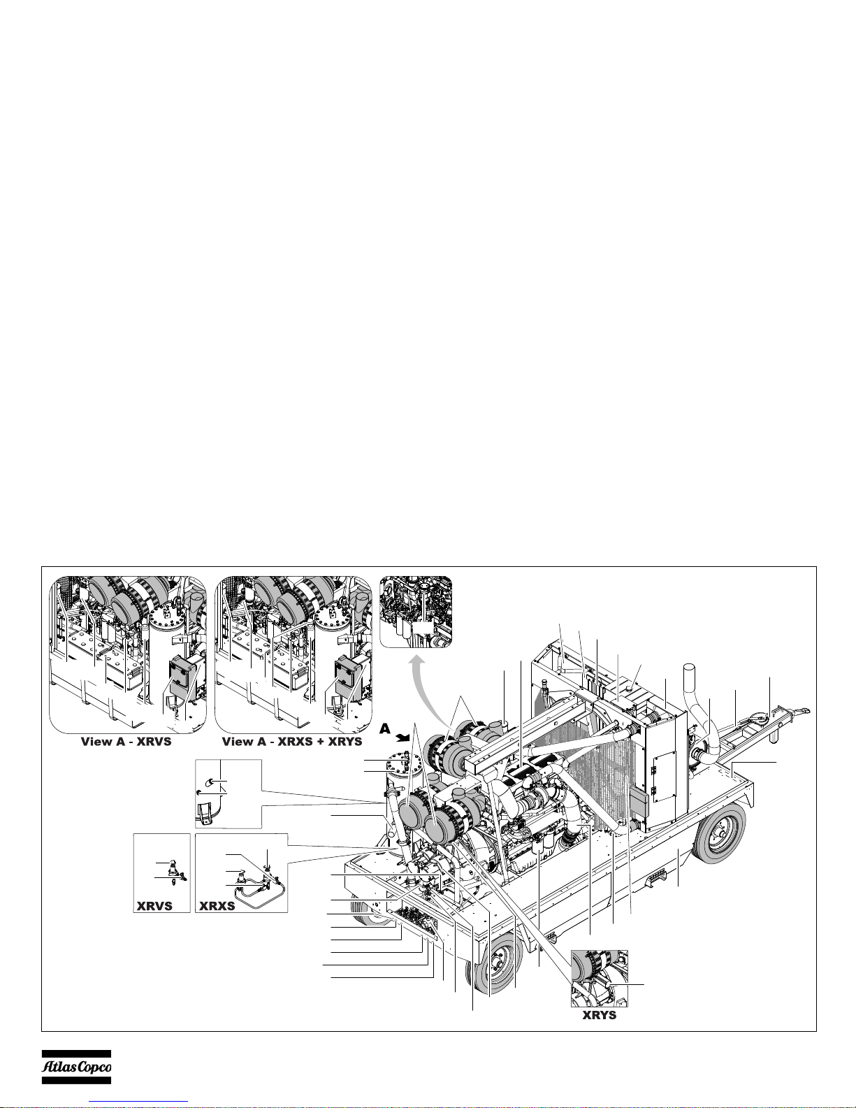
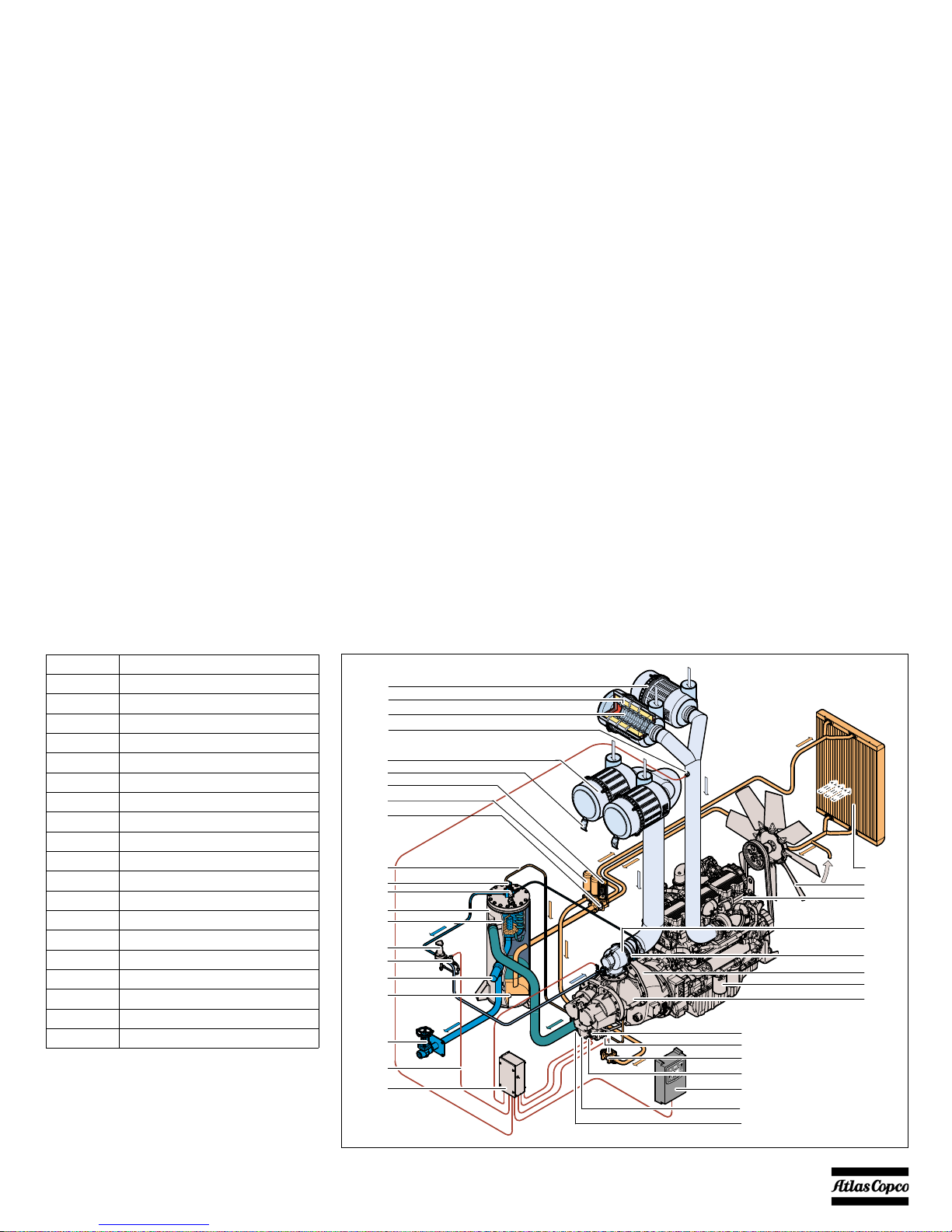
- 16 -
Main parts
(RV)
(LV)
(LV)
(FPco)
(OLG)
(RVlp)
(RVhp)
(PSS)
(BF)
(OFce)
(OFce)
(CU)
(CU)
(C)
(C)
(OT)
(BS)
(BS)
(B)
(B)
(FFp)
(FFp)
(FFf)
(FFf)
(AOV)
(TSlp)
(PS)
(CElp)
(OFe)
(EP)
(FL)
(F)
(FT)
(SN)
(TB)
(BH)
(DPF)
(IC)
(FCc)
(CLS)
(FC)
(R)
(OC)
(SV)
(AR)
(MPV)
(E)
(FFp)
(AFe)
(AFce)
(TShp)
(CEhp)
(DPar)
(DPce)
(DPgc)
(DPoc)
(DPr)
(DPeo)
(UV)
(ASV)

- 17 -
Reference Name
AFce Air Filter (compressor element)
AFe Air Filter (engine)
AOV Air Outlet Valves
AR Air Receiver
ASV AirXpert Stepper Valve (XRYS)
B Battery
BF Breather Filter
BH Brake Handle
BS Battery Switch
C Cubicle
CEhp Compressor Element (high pressure)
CElp Compressor Element (low pressure)
CLS Coolant Level Switch
CU Control Unit
DPar Drain Plug Air Receiver
DPce Drain Plug Compressor Element
DPeo Drain Plug Engine Oil
DPF Diesel Particulate Filter
DPgc Drain Plug Gear Casing
DPoc Drain Plug Oil Cooler
DPr Drain Plug Radiator
E Engine
Reference Name
EP Exhaust Pipe
FFan
FC Fuel Cooler
FCc Filler Cap (coolant)
FFp Fuel Prefilter
FFf Fuel Fine Filter Caterpillar
FL Fuel Level
FPco Filler Plug (oil compressor element)
FT Fuel Tank
IC Intercooler
LV Loading Valve (XRVS + XRXS)
MPV Minimum Pressure Valve
OC Oil Cooler
OFce Oil Filter (compressor element)
OFe Oil Filter (engine)
OLG Oil Level Gauge
OT Oiltronix
PS Pressure Switch
PSS Pressure Selection Switch (XRXS)
RRadiator
RV Regulating Valve (XRVS + XRXS)
Reference Name
RVhp Regulating Valve (high pressure)
(XRXS)
R Vlp Regulating Valve (low pressure)
(XRXS)
SN Serial Number
SV Safety Valve
TB Towbar
TShp Temperature Sensor (high pressure)
TSlp Temperature Sensor (low pressure)
UV Unloading Valve (XRVS + XRXS)
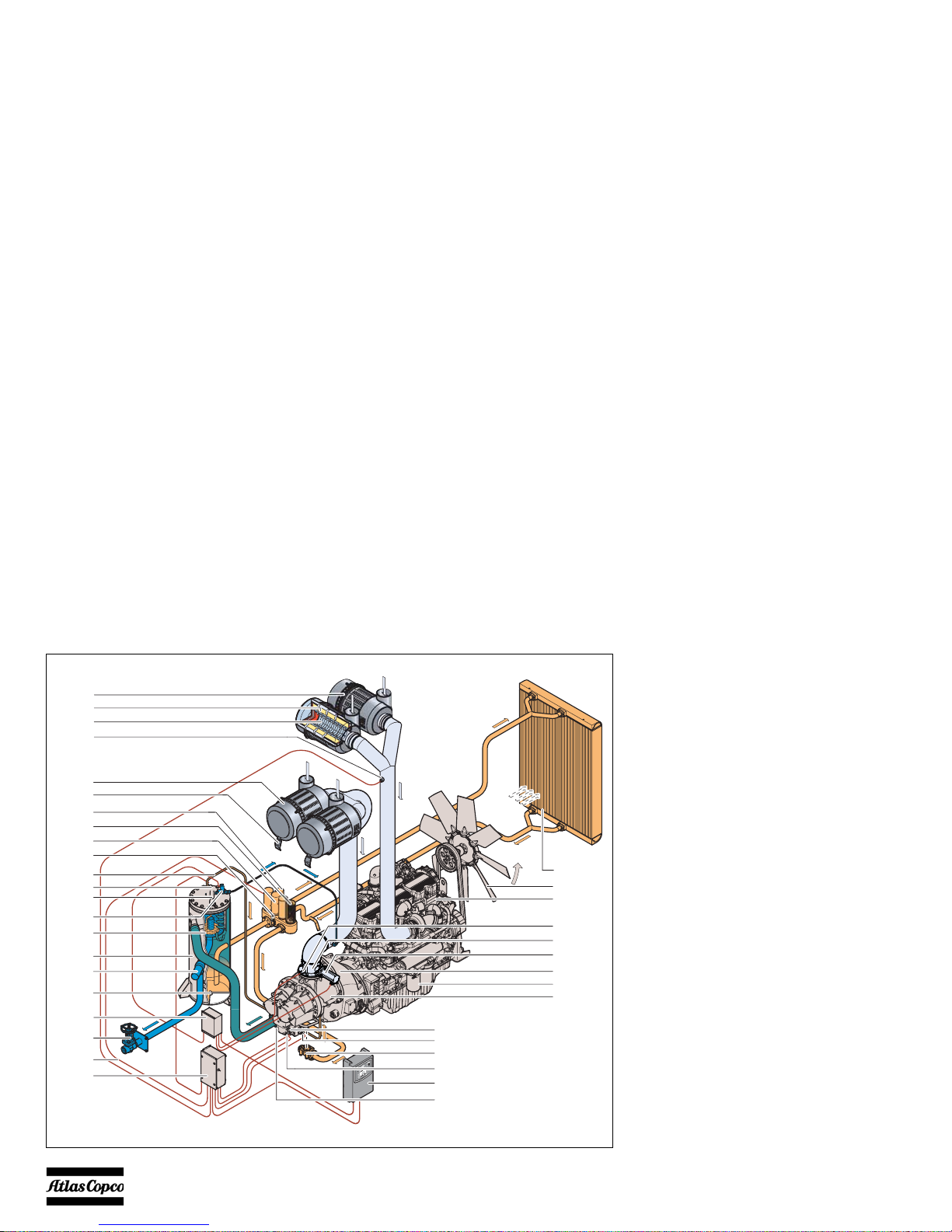
- 18 -
REGULATING SYSTEM
OVERVIEW
(BVof)
(AFe)
(AFE)
(SC)
(AFS)
(AFc)
(DE)
(WPS)
(OT)
(OFc)
(SL)
(TBV)
(AR)
(SV)
(OSE)
(MPV)
(DP)
(AOV)
(EW)
(C)
(DAXc)
(BOsv)
(PSlp)
(TShp)
(OSV)
(TSlp)
(CU)
(CEhp)
(OC)
(F)
(E)
(CH)
(OFe)
(CElp)
(PSai)
(DAXiv)
(DAXsm)
XRYS

- 19 -
Reference Name
AFE Air Filter Element
AFc Air Filter (compressor)
AFe Air Filter (engine)
AFS Air Filter Switch
AOV Air Outlet Valve
AR Air Receiver
BVof Bypass Valve oil filter
BOsv Blow Off System Solenoid Valve
C Cubicle
CEhp Compressor Element (high pressure)
CElp Compressor Element (low pressure)
CH Coupling Housing
CU Control Unit
DAXiv DrillAirXpert Inlet Valve
DAXsm DrillAirXpert Stepper Motor
DE Dust Evacuator
DP Drain Plug
E Engine
EW Electrical Wiring
FFan
MPV Minimum Pressure Valve
OC Oil Cooler
OFc Oil Filter (compressor)
OFe Oil Filter (engine)
Reference Name
OSE Oil Separator Element
OSV Oil Stop Valve
OT Oiltronix
PSai Pressure Sensor (air inlet)
PSlp Pressure Sensor (low pressure)
SC Safety Cartridge
SL Scavenge Line
SV Safety Valve
SVbos Solenoid Valve (blow off system)
TBV Thermostatic Bypass Valve
TShp Temperature Switch (high pressure)
TSlp Temperature Switch (low pressure)
WPS Working Pressure Sensor
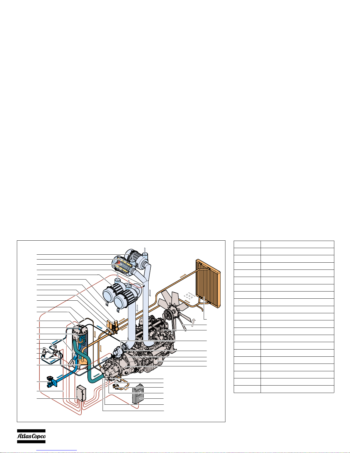
- 20 -
(AFe)
(AFE)
(SC)
(AFS)
(AFce)
(DE)
(BVof)
(OFce)
(TBV)
(SL)
(WPS)
(AR)
(SV)
(OSE)
(MPV)
(RVhp)
(LV)
(DP)
(AOV)
(EW)
(C)
(OT)
(PSS)
(OC)
(F)
(E)
(UA)
(BOV)
(CH)
(CElp)
(PSlp)
(TShp)
(OSV)
(TSlp)
(CU)
(CEhp)
(CV)
(OFe)
(RVlp)
XRXS
Reference Name
AFce Air Filter (compressor element)
AFE Air Filter Element
AFe Air Filter (engine)
AFS Air Filter Switch
AOV Air Outlet Valves
AR Air Receiver
BOV Blow Off Valve
BVof Bypass Valve oil filter
C Cubicle
CEhp Compressor Element (high pressure)
CElp Compressor Element (low pressure)
CH Coupling Housing
CU Control Unit
CV Check Valve
DE Dust Evacuator
DP Drain Plug
EEngine
EW Electrical Wiring
FFan
LV Loading Valve
- 21 -
Reference Name
MPV Minimum Pressure Valve
OC Oil Cooler
OFce Oil Filter (compressor element)
OFe Oil Filter (engine)
OSE Oil Separator Element
OSV Oil Stop Valve
OT Oiltronix
PSlp Pressure Sensor (low pressure)
PSS Pressure Selection Switch
R V Regulating Valve
R Vlp Regulating Valve (low pressure)
SC Safety Cartridge
SL Scavenge Line
SV Safety Valve
TBV Thermostatic Bypass Valve
TShp Temperature Sensor (high pressure)
TSlp Temperature Sensor (low pressure)
UA Unloader Assembly
WPS Working Pressure Sensor
(AFe)
(AFE)
(SC)
(AFS)
(AFce)
(DE)
(BVof)
(OFce)
(TBV)
(SL)
(WPS)
(AR)
(SV)
(OSE)
(MPV)
(RV)
(LV)
(DP)
(AOV)
(EW)
(C)
(OC)
(F)
(E)
(UA)
(BOV)
(CH)
(OFe)
(CElp)
(PSlp)
(TShp)
(OSV)
(TSlp)
(CU)
(CEhp)
(CV)
XRVS

- 22 -
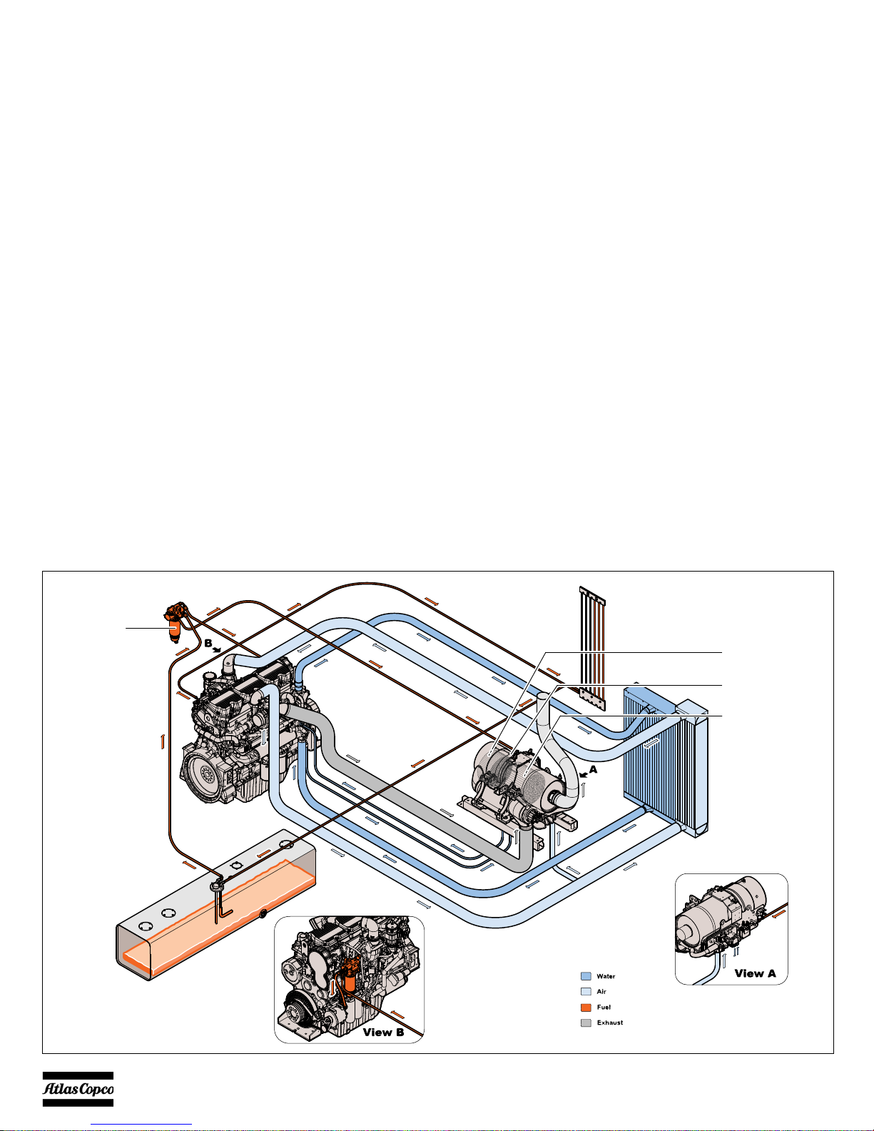
AIR FLOW (ALL UNITS)
Air drawn through the airfilter (AFce) into the
compressor element (CElp CEhp) is compressed. At
the element outlet, compressed air and oil pass into
the air receiver/oil separator (AR/OS).
The check valve (CV) prevents blow-back of
compressed air when the compressor is stopped. In
the air receiver/oil separator (AR/OS), most of the oil
is removed from the air/oil mixture.
The oil collects in the receiver and on the bottom of
the separator element.
The air leaves the receiver via a minimum pressure
valve (MPV) which prevents the receiver pressure
from dropping below the minimum working press ure,
even when the air outlet valves are open (specified in
section Limitations). This ensures adequate oil
injection and prevents oil consumption. The
minimum pressure valve (MPV) also functions as a
check valve.
The system comprises temperature sensors (TS),
pressure sensors (PS) and a working pressure sensor
(WPS).
OIL SYSTEM (ALL UNITS)
The lower part of the air receiver (AR) serves as an oil
tank.
Air pressure forces the oil from the air receiver/oil
separator (AR/OS) through the oil cooler (OC), the oil
filters (OF) and the oil stop valve (OSV) to the
compressor element (CElp CEhp).
When the compressor is stopped and / or there is no
pressure in the system, the oil stop valve (OSV)
prevents the oil from flowing back into the
compressor element.
The thermostatic by-pass valve (TBV) starts opening
when the oil temperature is 80°C (176°F) (when no
Oiltronix is installed). With installed Oiltronix, the
thermostatic by-pass valve starts opening when the oil
temperature is 40°C (104°F).
The compressor element has an oil gallery in the
bottom of its casing. The oil for rotor lubrication,
cooling and sealing is injected through holes in the
gallery.
Lubrication of the bearings is ensured by oil injected
into the bearing housings.
The injected oil, mixed with the compressed air,
leaves the compressor element and re-enters the air
receiver, where it is separated from the air as
described in section Air flow (all units). The oil that
collects on the bottom of the oil separator element is
returned to the system through a scavenging line (SL),
which is provided with a flow restrictor.
The oil filter by-pass valve (BVof) opens when the
pressure drop over the filter is above normal because
of a clogged filter. The oil then by-passes the filter
without being filtered. For this reason, the oil filter
must be replaced at regular intervals (see section
Preventive maintenance schedule).
Oiltronix (XRYS + XRXS)
The oil system of XRYS and XRXS units is equipped
with the Oiltronix
ΤΜ
system, a system that
electronically controls oil temperature:
• At all time the oil temperature is kept to a
minimum to elongate the lifetime of oil and
compressor elements and to ensure proper
lubrication.
• The oil temperature is also controlled at all time to
a minimum level above the dewpoint, preventing
water vapour to condense in the vessel or oil
system.
The optimum temperature is calculated based on
ambient conditions and operating conditions. In a
next step the 3-way valve is positioned in order to
achieve this optimal oil temperature by more or less
bypassing the oil cooler. In this way oil temperature
regulation is more efficient.

- 23 -
The compressor is provided with a continuous
pneumatic regulating system and a blow-off valve
(BOV), which is integrated in the unloader assembly
(UA). The valve is closed during operation by outlet
pressure of the compressor element and opens by air
receiver pressure when the compressor is stopped.
When the air consumption increases, the air receiver
pressure will decrease and vice versa. This receiver
pressure variation is sensed by the regulating valve
(RVlp RVhp) which, by means of control air to the
unloader assembly (UA), matches the air output to the
air consumption. The air receiver pressure is
maintained between the pre-selected working
pressure and the corresponding unloading pressure.
When starting the compressor, the throttle valve is
kept closed via receiver pressure. The compressor
element (CElp CEhp) takes in air and pressure builds
up inside the receiver (AR). The throttle valve is
closed. The air output is controlled from maximum
output (100%) to no output (0%) by:
1. Speed control of the engine between maximum
load speed and unloading speed (the output of a
screw compressor is proportional to the rotating
speed).
2. Air inlet throttling.
If the air consumption is equal to or exceeds the
maximum air output, the engine speed is held at
maximum load speed and the throttle valve is fully
open.
If the air consumption is less than the maximum air
output, air receiver pressure increases and the
regulating valve supplies control air to throttle valve
to reduce the air output and holds air receiver pressure
between the normal working pressure and the
corresponding unloading pressure. Unloading
pressure = normal working pressure + 1 bar (14.504
psi).
When the air consumption is resumed, the blow off
valve (BOV) closes and the throttle valve gradually
opens the air intake and the electronic speed regulator
increases the engine speed.
The construction of the regulating valve (RV) is such
that any increase (decrease) of the air receiver
pressure above the pre-set valve opening pressure
results in a proportional increase (decrease) of the
control pressure to the throttle valve and the
electronic speed regulator.
Part of the control air is vented into the atmosphere,
and any condensate discharged, through the vent
holes.
ELECTRONIC REGULATING SYSTEM (XRYS)
To be able to control pressure and flow the AirXpert
system watches:
• Ambient air pressure and temperature
• Compressor air inlet pressure
• Vessel pressure and temperature
Depending on the selection Pressure control or Flow
control, the compressor air inlet pressure, the engine
speed and the blow off valve are controlled to keep
the selected setting value (pressure or flow).
The system comprises temperature sensors (TShp
TSlp), pressure sensors (PSlp) and a working pressure
sensor (WPS).
CONTINUOUS PNEUMATIC REGULATING SYSTEM (XRVS + XRXS)
- 24 -
FLOW DIAGRAM EXHAUST AFTERTREATMENT
(HPFP)
(DOC)
(EAM)
(DPF)

- 25 -
EXHAUST GAS AFTERTREATMENT (ALL UNITS)
To meet the demands of Stage IIIB / Tier 4 Interim
Emission Legislation, the engine is equipped with an
exhaust aftertreatment module (EAM), consisting of
an exhaust gas recirculation system and a particulate
filter. The exhaust gas is fully automatically cleaned.
The process is monitored by the machine controller.
Step 1 Exhaust Gas Recirculation
With Exhaust Gas Recirculation (EGR), part of the
exhaust gases are cooled and then injected back into
the engine cylinders to reduce NOx.
Exhaust gas is cooled to allow the introduction of a
greater mass of recirculated gas.
The outcome is a lower peak combustion
temperature.
Step 2 Diesel Particulate Filter + Diesel
Oxidation Catalyst
To remove excess particulate matter from the exhaust
gas, a Diesel Particulate Filter (DPF) is used. This
system consists of a Diesel Oxidation Catalyst (DOC)
and a filter module. The DOC reduces CO, HC and
NO through oxidation. It also produces NO
2
to
regenerate the DPF. The filter system removes 99%
of particulate matter.
Step 3 Active regeneration
Particulate matter left in the filter system is burned in
a process called regeneration. Extending the lifetime
of a filter, it converts particulate matter into CO
2
and
ash. Atlas Copco engines use high temperature
regeneration that includes a fuel burner in the exhaust
stream that intermittently raises the temperature
above 600º C / 1100° F.
A separate High Pressure Fuel Pump (HPFP) supplies
fuel to the burner in the active regeneration system.
Active regeneration decreases in the higher load
cycles of the compressor.
Step 4 Ash removal
Additives in lube oil that do not combust during
regeneration, turn into ash. This reduces filter
volume, oxidation efficiency and backpressure.
Ash must be removed mechanically, according a
service interval, either by washing or blowing it out.
This service interval can be increased depending on
duty cycle.

- 26 -
ELECTRIC SYSTEM
CIRCUIT DIAGRAM INDEX
9822 0963 68
Tag Desc. 1 Desc. 2 Sheet Col.
B1 Namur sensor Bypass
B2 Namur sensor Closed
B3 Combo sensor
B4 Namur sensor Bypass
B5 Namur sensor Closed
F1 Circuit breaker Main
F10 Circuit breaker 10A Roof actuator
F13 Circuit breaker Charging alternator
F2 Circuit breaker Engine control module
F3 Circuit breaker CAT regeneration system
F4 Circuit breaker Fuel priming pump
F6 Circuit breaker Refuel pump
F8 Circuit breaker 15A Internal lights
F9 Circuit breaker Preheater/Nordic
G1 Battery
G2 Battery
G3 Charging alternator
H10 Light Internal
H11 Light Internal
H4 Flasher light
H6 Horn
H7 Flasher light
H8 Light Internal
H9 Light Internal
Tag Desc. 1 Desc. 2 Sheet Col.
K0 Solenoid Starter motor
K1 Relay Fuel priming pump
K10 Relay Remote control
K11 Relay Roof actuator
K12 Relay Micro PLC
K13 Relay Etherstart
K2 Relay Compressor P.A.C.
K3 Relay Refuel pump
K4 Relay Air shut-off valve
K5 Relay Aftercooler fans
K6 Relay Internal lights
K8 Relay Heater
LS1 Level switch Coolant level warning
LS2 Level switch Coolant level shutdown
LT1 Level sensor Fuel level
M1 Starter motor
M3 Pump Refuel pump
M4 Fan Aftercooler
M5 Fan Aftercooler
M6 Pump Preheater
M7 Stepper motor Oiltronix
M8 Motor Roof actuator
M9 Stepper motor AirXpert
N1 Connector Engine control module

- 27 -
9822 0963 68
Tag Desc. 1 Desc. 2 Sheet Col.
PS1 Pressure switch ΔP airfilter
PT1 Pressure sensor Vessel pressure
PT2 Pressure sensor Regulating pressure
PT3 Pressure sensor Interstage pressure
PT4 Pressure sensor Oil Stop valve pressure
PT5 Pressure sensor Aftercooler air discharge
pressure
R1 End resistor J1939 CAN Bus
R2 End resistor J1939 CAN Bus
S10 Switch Emergency stop
S11 Switch Battery cut-off
S12 Switch Remote emergency stop
S13 Switch Battery cut-off
S10 Switch Emergency stop
S2 Switch External fuel
S3 Switch Fuel priming pump
S4 Switch Battery cut-off
S5 Switch Emergency stop
S6 Switch Dual pressure
S8 Switch Limit switch
S9 Switch Internal lights
TT1 Temperature sensor LP element temperature
TT2 Temperature sensor HP element temperature
TT3 Temperature sensor Ambient temperature
TT4 Temperature sensor Ambient temperature
TT5 Temperature sensor Aftercooler air discharge
temperature
TT6 Temperature sensor Air discharge temperature
Tag Desc. 1 Desc. 2 Sheet Col.
X1 Connector XC3003/4003 primary
X10A Connector Air shut-off valve
X10B Connector Preheater
X10C Connector Internal lights
X10D Connector Dual pressure/preset
X11 Remote control Receiver
X11 Remote control Receiver
X11 Remote control Receiver
X2 Connector XC3003/4003 secondary
X3 Connector XC3003/4003 remote
X4 Connector CAT diagnostic
X5 Connector CAT interconnect harness
X60 Connector COSMOS module
X61 Connector COSMOS satellite
X62 Connector COSMOS PC
X7 Connector Roof actuator controller
X8 Connector Limit switch
X9 Connector Option box
XPH1 Connector Coolant heater
XPH2 Connector Timer
Y1 Solenoid valve Load
Y2 Solenoid valve Blow down
Y4 Solenoid Etherstart
Y5 Solenoid valve Air shut-off valve
Y6 Solenoid Dual preset
Y7 Solenoid Dual pressure
- 28 -
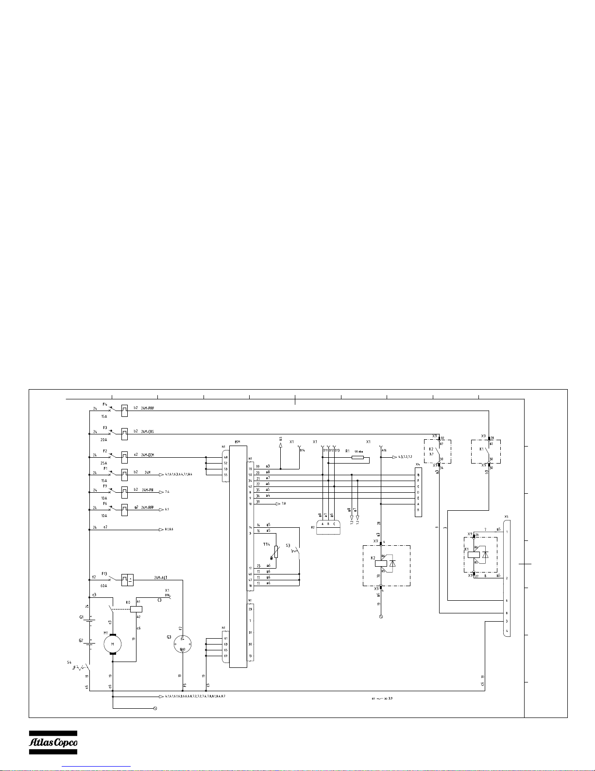
SH3 ENGINE CIRCUIT
1
2
3
5
6
7
8
9
G
4
10
A
B
C
D
E
F
3-A 3-B 3-D
3-C
3-E
3-G
3-H
3-I
3-F
9822 0963 68

- 29 -
Reference Name
3-A Engine PAC
3-B CCM CAN Bus
3-C CAN End Resistor
3-D Compressor PAC
3-E Relay for CRS Power
3-F Diagnostic
3-G Relay for CRS Pump
3-H CAT Interconnect 12 Pole
3-I STD Engine

- 30 -
SH4 COMPRESSOR CIRCUIT
9822 0963 68
 Loading...