

Atlas Copco GA18, GA22, GA30C, GA30, GA11 User Manual
...
Atlas Copco Stationary Air Compressors
GA5-7-11C-11-15-18-22-30C-30-37-45-55C-55-75-90C and
GA30 W-37 W-45 W-55C W-55 W-75 W-90C W
With Elektronikon I or Elektronikon II regulator
User manual for Elektronikon® I and II regulators

Compressor type: . . . . . . . . . . . . . . . . . . . . . . . . . . . . . . . . . . . . . . . . Unit serial No. compressor: . . . . . . . . . . . . . . . . . . . . . . . . . . . . . . . . . . . .
Air dryer type: . . . . . . . . . . . . . . . . . . . . . . . . . . . . . . . . . . . . . . . . . . Unit serial No. dryer: . . . . . . . . . . . . . . . . . . . . . . . . . . . . . . . . . . . . . . . . .
Motor type: . . . . . . . . . . . . . . . . . . . . . . . . . . . . . . . . . . . . . . . . . . . . . Motor serial No.: . . . . . . . . . . . . . . . . . . . . . . . . . . . . . . . . . . . . . . . . . . . .
Delivery date: . . . . . . . . . . . . . . . . . . . . . . . . . . . . . . . . . . . . . . . . . . . First start-up date: . . . . . . . . . . . . . . . . . . . . . . . . . . . . . . . . . . . . . . . . . . .
Service Plan: . . . . . . . . . . . . . . . . . . . . . . . . . . . . . . . . . . . . . . . . . . . . Owner's machine No.: . . . . . . . . . . . . . . . . . . . . . . . . . . . . . . . . . . . . . . . .
Selected lubricants
Compressor: . . . . . . . . . . . . . . . . . . . . . . . . . . . . . . . . . . . . . . . . . . . . Capacity: . . . . . . . . . . . . . . . . . . . . . . . . . . . . . . . . . . . . . . . . . . . . . . . . . .
Bearing grease type, electric motor: . . . . . . . . . . . . . . . . . . . . . . . . .
Dryer gearbox . . . . . . . . . . . . . . . . . . . . . . . . . . . . . . . . . . . . . . . . . . . Capacity . . . . . . . . . . . . . . . . . . . . . . . . . . . . . . . . . . . . . . . . . . . . . . . . . . .
Printed Matter Nos.
Atlas Copco compressor instruction book: . . . . . . . . . . . . . . . . . . . . Atlas Copco air dryer instruction book: . . . . . . . . . . . . . . . . . . . . . . . . . .
Atlas Copco compressor parts list: . . . . . . . . . . . . . . . . . . . . . . . . . . Atlas Copco air dryer parts list: . . . . . . . . . . . . . . . . . . . . . . . . . . . . . . . .
Atlas Copco logbook: . . . . . . . . . . . . . . . . . . . . . . . . . . . . . . . . . . . . .
Local Atlas Copco Representative
Name: . . . . . . . . . . . . . . . . . . . . . . . . . . . . . . . . . . . . . . . . . . . . . . . . . . . . . . . . . . . . . . . . . . . . . . . . . . . . . . . . . . . . . . . . . . . . . . . . . . . . . . . . . . . . . . .
Address: . . . . . . . . . . . . . . . . . . . . . . . . . . . . . . . . . . . . . . . . . . . . . . . . . . . . . . . . . . . . . . . . . . . . . . . . . . . . . . . . . . . . . . . . . . . . . . . . . . . . . . . . . . . . . .
Telephone: . . . . . . . . . . . . . . . . . . . . . . . . . . . . . . . . . . . . . . . Contact persons: Service: . . . . . . . . . . . . . . . . . . . . . . . . . . . . . . . . . . . . . . . . . . . . .
Telex: . . . . . . . . . . . . . . . . . . . . . . . . . . . . . . . . . . . . . . . . . . Parts: . . . . . . . . . . . . . . . . . . . . . . . . . . . . . . . . . . . . . . . . . . . . . . .
E-mail . . . . . . . . . . . . . . . . . . . . . . . . . . . . . . . . . . . . . . . . . . . . . . . . . . . . . . . . . . . . . . . . . . . . . . . . . . . . . . . . . . . . . . . . . . . . . . . . . . . . . . . . . . . . . . .
SAFETY PRECAUTIONS
To be read attentively and acted accordingly before installing, operating or repairing the unit.
These recommendations apply to machinery processing or consuming air or inert gas. Processing of any other gas requires
additional safety precautions typical to the application which are not included herein.
If necessary, install a suction duct. Never obstruct the air inlet. Care
shall be taken to minimize the entry of moisture with the inlet air.
4. The aspirated air shall be free from flammable fumes or vapours,
e.g. paint solvents, that can lead to internal fire or explosion.
5. Air-cooled units shall be installed in such a way that an adequate
flow of cooling air is available and that the exhausted air does not
recirculate to the inlet.
6. Arrange the air intake so that loose clothing of people cannot be
sucked in.
7. Ensure that the discharge pipe from the compressor to the aftercooler,
air dryer or air net is free to expand under heat and that it is not in
contact with or close to flammable material.
8. No external force may be exerted on the air outlet valve; the connected
pipe must be free of strain.
9. If remote control is installed, the unit shall bear an obvious sign
reading:
DANGER: This machine is remotely controlled and may start
without warning.
As a further safeguard, persons switching on remotely controlled
units shall take adequate precautions to ensure that there is no one
checking or working on the machine. To this end, a suitable notice
shall be affixed to the start equipment.
10. On units with automatic start-stop system, a sign stating "This
machine may start without warning" shall be attached near the
instrument panel.
11. In multiple compressor systems manual valves shall be installed to
isolate each compressor. Non-return valves (check valves) shall not
be relied upon for isolating pressure systems.
12. Never remove or tamper with the safety devices, guards or insulations
fitted on the unit. Every pressure vessel or auxiliary installed outside
the unit to contain air above atmospheric pressure shall be protected
by a pressure-relieving device or devices as required.
13. Pipework or other parts with a temperature in excess of 80 degrees
celsius and which may be accidentally touched by personnel in normal operation shall be guarded or insulated. Other high-temperature
pipework shall be clearly marked.
OWNERSHIP DATA
In addition to normal safety rules which should be observed with stationary
air compressors and equipment, the following safety directions and
precautions are of special importance.
When operating this unit, the operator must employ safe working practices
and observe all related local work safety requirements and ordinances.
The owner is responsible for maintaining the unit in a safe operating
condition. Parts and accessories shall be replaced if unsuitable for safe
operation.
Installation, operation, maintenance and repair shall only be performed
by authorized, trained, competent personnel.
Normal ratings (pressures, temperatures, time settings, etc.) shall be
durably marked.
Any modification on the compressor or air dryer shall only be performed
in agreement with Atlas Copco and under supervision of authorized,
competent personnel.
If any statement in this book, especially with regard to safety, does not
comply with local legislation, the stricter of the two shall apply.
These precautions are general and cover several machine types and
equipment; hence some statements may not apply to the unit(s) described
in this book.
Installation
Apart from general engineering practice in conformity with the local
safety regulations, the following directives are specially stressed:
1. A compressor or air dryer shall be lifted only with adequate equipment
in conformity with local safety rules.
Loose or pivoting parts shall be securely fastened before lifting. It is
strictly forbidden to dwell or stay in the risk zone under a lifted load.
Lifting acceleration and retardation shall be kept within safe limits.
Wear a safety helmet when working in the area of overhead or lifting
equipment.
2. Any blanking flanges, plugs, caps and desiccant bags shall be
removed before connecting up the pipes. Distribution pipes and
connections shall be of correct size and suitable for the working
pressure.
3. Place the unit where the ambient air is as cool and clean as possible.
2920 1377 03 1/2 (continued on inside of cover)

Atlas Copco Stationary Air Compressors
Important
This book applies exclusively to the above-mentioned compressors with
Elektronikon I or II regulator from following serial numbers onwards:
GA5 up to GA11C: AII-145 000
GA11 up to GA30C: AII-268 500
GA30 up to GA55C: AII-380 000
GA55 up to GA90C: AII-474 000
No. 2920 1461 03
Replaces 2920 1461 02
Registration code: APC G5-11C/2002 / 38 / 984
APC G11-30C / 38 / 989
APC G30-55C / 38 / 980
APC G55-90C / 38 / 985
2003-09
GA5-7-11C-11-15-18-22-30C-30-37-45-55C-55-75-90C and
GA30 W-37 W-45 W-55C W-55 W-75 W-90C W
With Elektronikon I or Elektronikon II regulator
User manual for Elektronikon® I and II regulators
·
Copyright 2003, Atlas Copco Airpower n.v., Antwerp, Belgium.
Any unauthorized use or copying of the contents or any part thereof is prohibited. This applies in
particular to trademarks, model denominations, part numbers and drawings.
·
This instruction book meets the requirements for instructions specified by the machinery
directive 98/37/EC and is valid for CE as well as non-CE labelled machines.
www.atlascopco.com

2920 1461 03
2
User manual
Page
7 Scrolling through all screens . . . . . . . . . . . . . . . . . . . . . . . . . 7
7.1 Calling up outlet/dewpoint temperatures . . . . . . . . . . . . 9
7.2 Calling up running hours . . . . . . . . . . . . . . . . . . . . . . . . 9
7.3 Calling up loading hours . . . . . . . . . . . . . . . . . . . . . . . . 9
7.4 Calling up motor starts . . . . . . . . . . . . . . . . . . . . . . . . . 10
7.5 Calling up/resetting service timer. . . . . . . . . . . . . . . . . 10
7.6 Automatic restart after voltage failure . . . . . . . . . . . . . 10
7.7 Set of parameters. . . . . . . . . . . . . . . . . . . . . . . . . . . . . . 11
7.8 Calling up/modifying unloading pressure . . . . . . . . . . 11
7.9 Calling up/modifying loading pressure . . . . . . . . . . . . 11
7.10 Calling up/modifying dewpoint warning temperature . 11
7.11 Calling up/modifying service timer setting . . . . . . . . . 12
7.12 Calling up/modifying unit for pressure . . . . . . . . . . . . 12
7.13 Calling up/modifying unit for temperature . . . . . . . . . 12
7.14 Selection between Y-D/DOL starting . . . . . . . . . . . . . . 12
7.15 Activating automatic restart after voltage failure. . . . . 13
7.16 Selecting local/remote control . . . . . . . . . . . . . . . . . . . 13
7.17 Modifying parameter set . . . . . . . . . . . . . . . . . . . . . . . . 13
8 Settings
. . . . . . . . . . . . . . . . . . . . . . . . . . . . . . . . . . . . . 14
8.1 Unloading/loading pressures . . . . . . . . . . . . . . . . . . . . 14
8.2 Element outlet temperature . . . . . . . . . . . . . . . . . . . . . . 14
8.3 Dewpoint temperature. . . . . . . . . . . . . . . . . . . . . . . . . . 14
8.4 Service timer . . . . . . . . . . . . . . . . . . . . . . . . . . . . . . . . . 14
Contents
PART 1 - ELEKTRONIKON I REGULATOR
Page
1 General description . . . . . . . . . . . . . . . . . . . . . . . . . . . . . . . . 3
1.1 Automatic control of the compressor . . . . . . . . . . . . . . 3
1.2 Protecting the compressor . . . . . . . . . . . . . . . . . . . . . . . 3
1.3 Automatic restart after voltage failure . . . . . . . . . . . . . . 3
2 Control panel . . . . . . . . . . . . . . . . . . . . . . . . . . . . . . . . . . . . . 3
3 Display . . . . . . . . . . . . . . . . . . . . . . . . . . . . . . . . . . . . . . . . . . . 4
3.1 Pictographs used on the screen . . . . . . . . . . . . . . . . . . . 4
3.2 Main screen . . . . . . . . . . . . . . . . . . . . . . . . . . . . . . . . . . . 4
3.3 Scrolling through all screens . . . . . . . . . . . . . . . . . . . . . 5
4 Shut-down warning . . . . . . . . . . . . . . . . . . . . . . . . . . . . . . . . 5
4.1 Compressor element outlet temperature . . . . . . . . . . . . . 5
4.2 Dewpoint temperature. . . . . . . . . . . . . . . . . . . . . . . . . . . 5
5 Shut-down
5.1 Compressor element outlet temperature . . . . . . . . . . . . . 6
5.2 Motor overload . . . . . . . . . . . . . . . . . . . . . . . . . . . . . . . . 6
6 Service warning . . . . . . . . . . . . . . . . . . . . . . . . . . . . . . . . . . . 7
PART 2 - ELEKTRONIKON II REGULATOR
Page
1 General description . . . . . . . . . . . . . . . . . . . . . . . . . . . . . . . 15
1.1 Automatic control of the compressor . . . . . . . . . . . . . 15
1.2 Protecting the compressor . . . . . . . . . . . . . . . . . . . . . . 15
1.3 Automatic restart after voltage failure . . . . . . . . . . . . . 15
2 Control panel . . . . . . . . . . . . . . . . . . . . . . . . . . . . . . . . . . . . 16
2.1 LEDs/buttons/keys . . . . . . . . . . . . . . . . . . . . . . . . . . . . 16
2.2 Pictographs . . . . . . . . . . . . . . . . . . . . . . . . . . . . . . . . . . 17
2.3 Function keys . . . . . . . . . . . . . . . . . . . . . . . . . . . . . . . . 17
3 Menu-driven control programs . . . . . . . . . . . . . . . . . . . . . 19
3.1 Function of control programs . . . . . . . . . . . . . . . . . . . . 19
3.2 Main screen . . . . . . . . . . . . . . . . . . . . . . . . . . . . . . . . . . 19
3.3 Calling up other menus . . . . . . . . . . . . . . . . . . . . . . . . . 19
4 Quick look at actual compressor status . . . . . . . . . . . . . . . 20
5 Status data menu . . . . . . . . . . . . . . . . . . . . . . . . . . . . . . . . . 20
5.1 No message exists . . . . . . . . . . . . . . . . . . . . . . . . . . . . . 20
5.2 A shut-down message exists . . . . . . . . . . . . . . . . . . . . . 20
5.3 A shut-down warning message exists . . . . . . . . . . . . . . 21
5.4 A service warning message exists . . . . . . . . . . . . . . . . 21
5.5 A warning message exists . . . . . . . . . . . . . . . . . . . . . . . 21
6 Measured data menu . . . . . . . . . . . . . . . . . . . . . . . . . . . . . . 22
7 Counters menu . . . . . . . . . . . . . . . . . . . . . . . . . . . . . . . . . . . 22
8 Test menu . . . . . . . . . . . . . . . . . . . . . . . . . . . . . . . . . . . . . 22
Page
9 Modify params menu . . . . . . . . . . . . . . . . . . . . . . . . . . . . . . 22
10 Modifying parameters . . . . . . . . . . . . . . . . . . . . . . . . . . . . . 23
10.1 Modifying loading/unloading pressures . . . . . . . . . . . . 23
11 Modifying protection settings . . . . . . . . . . . . . . . . . . . . . . . 23
11.1 Modifying settings for compressor element . . . . . . . . . 24
12 Modifying service plans. . . . . . . . . . . . . . . . . . . . . . . . . . . . 24
13 Programming clock function. . . . . . . . . . . . . . . . . . . . . . . . 25
13.1 Programming start/stop/pressure band commands . . . 25
13.2 To activate/deactivate the timer . . . . . . . . . . . . . . . . . . 26
13.3 To modify a command . . . . . . . . . . . . . . . . . . . . . . . . . 26
13.4 To add a command . . . . . . . . . . . . . . . . . . . . . . . . . . . . 27
13.5 To delete commands . . . . . . . . . . . . . . . . . . . . . . . . . . . 27
14 Configuration menu . . . . . . . . . . . . . . . . . . . . . . . . . . . . . . . 28
14.1 Programming compressor control modes . . . . . . . . . . . 28
15 Service menu . . . . . . . . . . . . . . . . . . . . . . . . . . . . . . . . . . . . . 28
16 Saved data menu . . . . . . . . . . . . . . . . . . . . . . . . . . . . . . . . . 29
17 Programmable settings . . . . . . . . . . . . . . . . . . . . . . . . . . . . 30
17.1 Parameters . . . . . . . . . . . . . . . . . . . . . . . . . . . . . . . . . . . 30
17.2 Protections . . . . . . . . . . . . . . . . . . . . . . . . . . . . . . . . . . . 31
17.3 Service plan . . . . . . . . . . . . . . . . . . . . . . . . . . . . . . . . . . 31
2920 1461 03
3
User manual
PART 1
ELEKTRONIKON I REGULATOR
1.3 Automatic restart after voltage failure
For compressors leaving the factory, this function is made
inactive. If desired, the function can be activated. Consult
Atlas Copco.
Warning If activated and provided the module was in the
automatic operation mode, the compressor will
automatically restart if the supply voltage to the
module is restored.
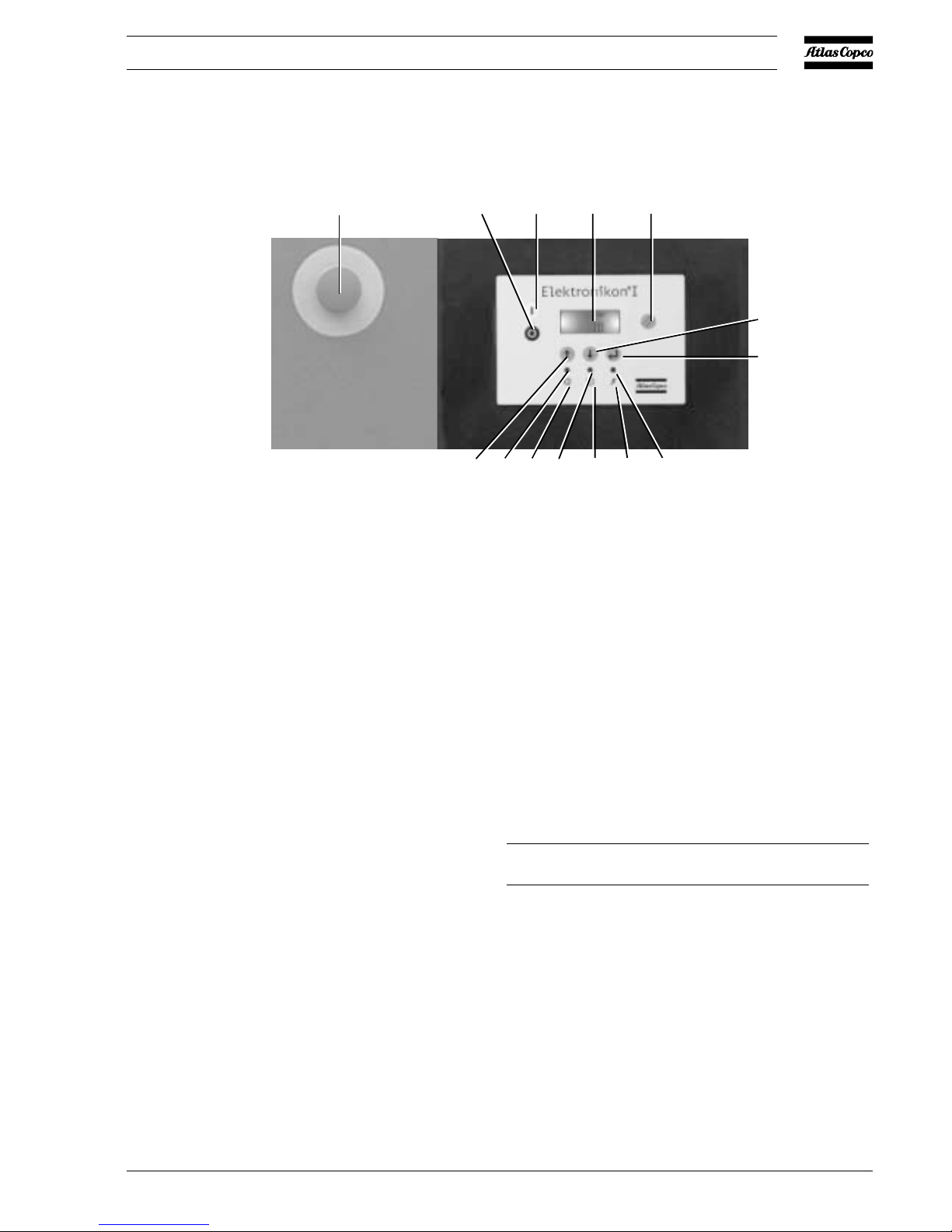
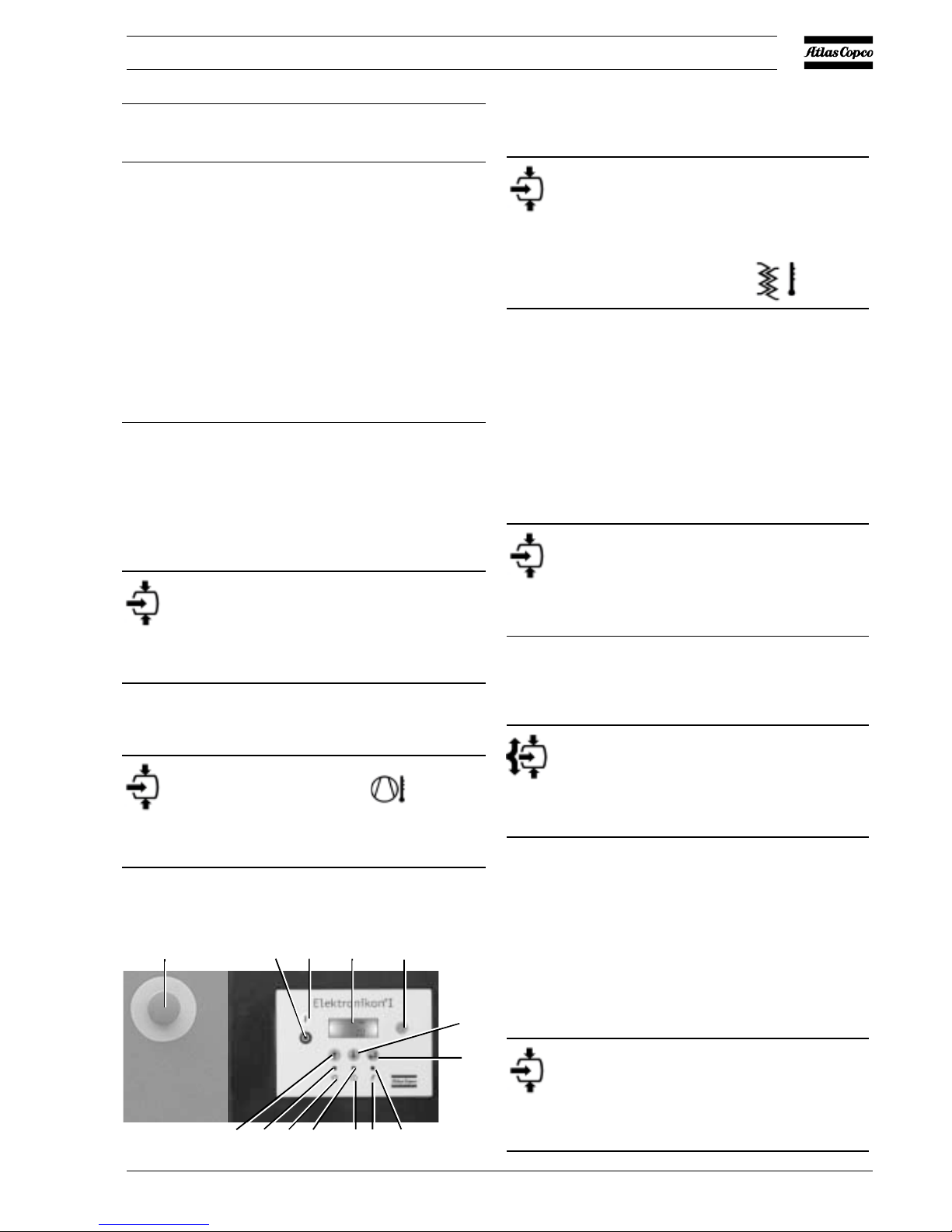
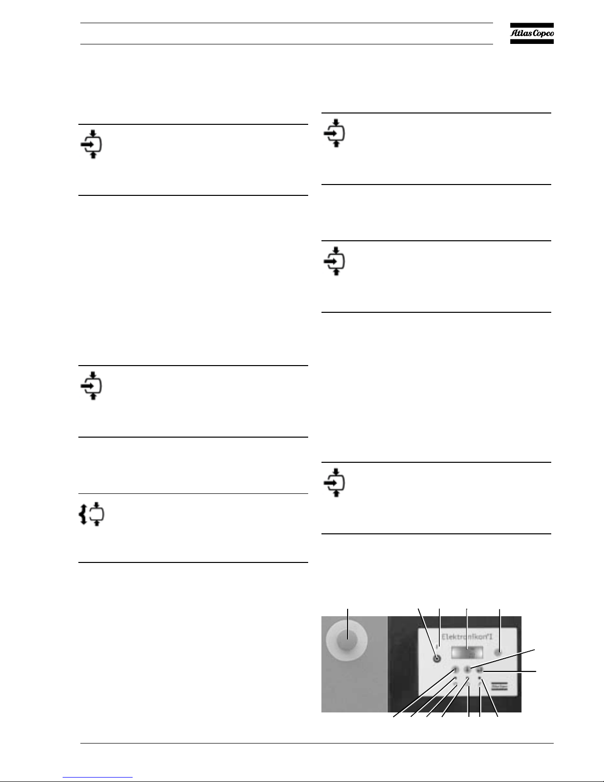
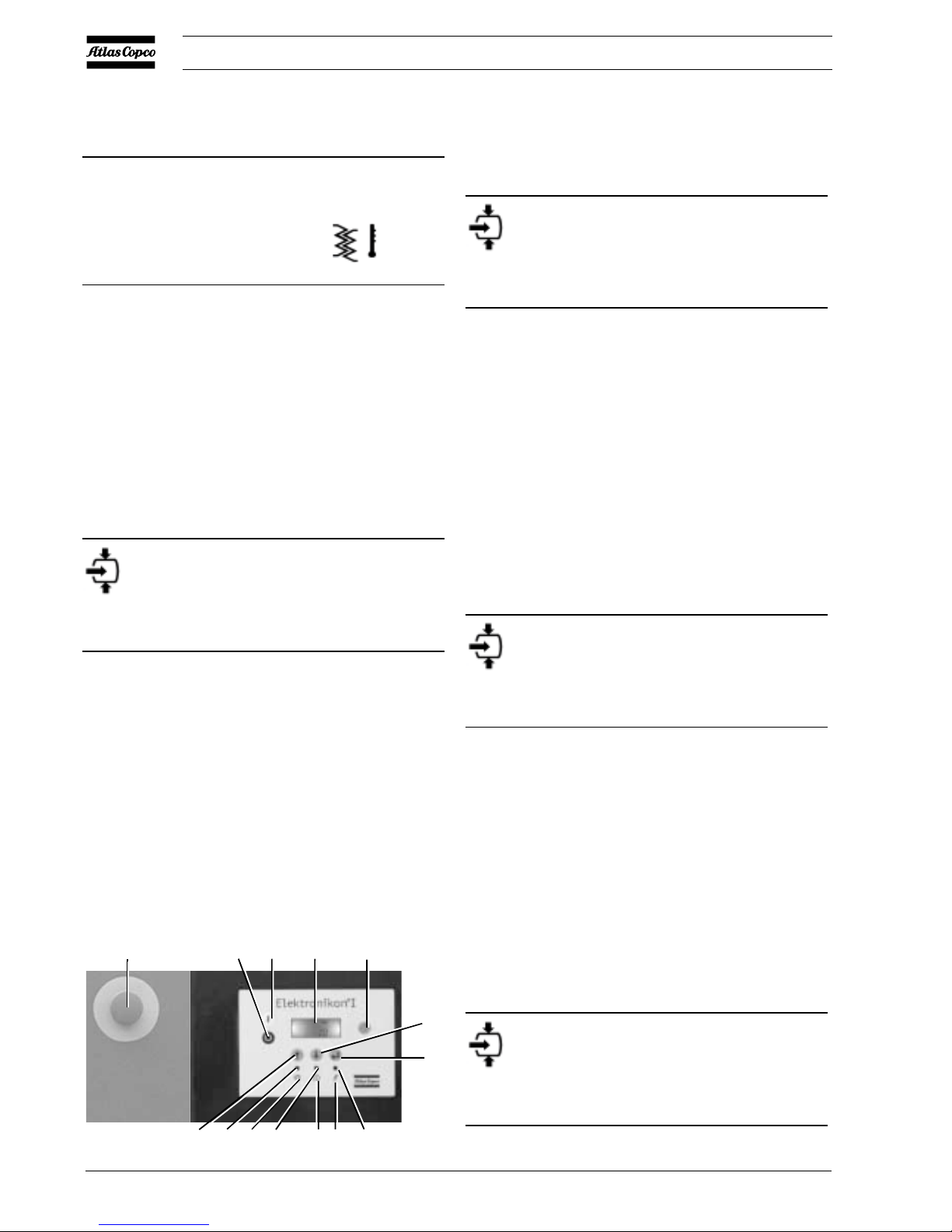
2 Control panel
Ref. Designation Function
1 Stop button Push button to stop the
compressor. LED (10) goes out.
The compressor will stop after
running in unloaded condition for
about 30 seconds.
2 Start button Push button to start the
compressor. LED (10) lights up
indicating that the regulator is
operative (in automatic operation).
3 Display Indicates the compressor operating
condition, measured values and
programmed parameters.
1 General description
1.1 Automatic control of the compressor
The regulator maintains the net pressure between programmable
limits by automatically loading and unloading the compressor.
A number of programmable settings, e.g. the unloading and
loading pressures, the minimum stop time and the maximum
number of motor starts are taken into account.
The regulator stops the compressor whenever possible to reduce
the power consumption and restarts it automatically when the
net pressure decreases.
1.2 Protecting the compressor
Shut-down
If the compressor element outlet temperature exceeds the
programmed shut-down level, the compressor will be stopped.
This will be indicated on display (3). The compressor will
also be stopped in case of overload of drive motor (M1) and,
for air-cooled compressors, also the fan motor (M2).
Shut-down warning
If the compressor element outlet temperature or dewpoint
temperature (Full-Feature compressors) exceeds a programmed
value below the shut-down level, this will also be indicated to
warn the operator before the shut-down level is reached.
Service warning
If the service timer exceeds a programmed value, this will be
indicated on display (3) to warn the operator to carry out some
service actions.
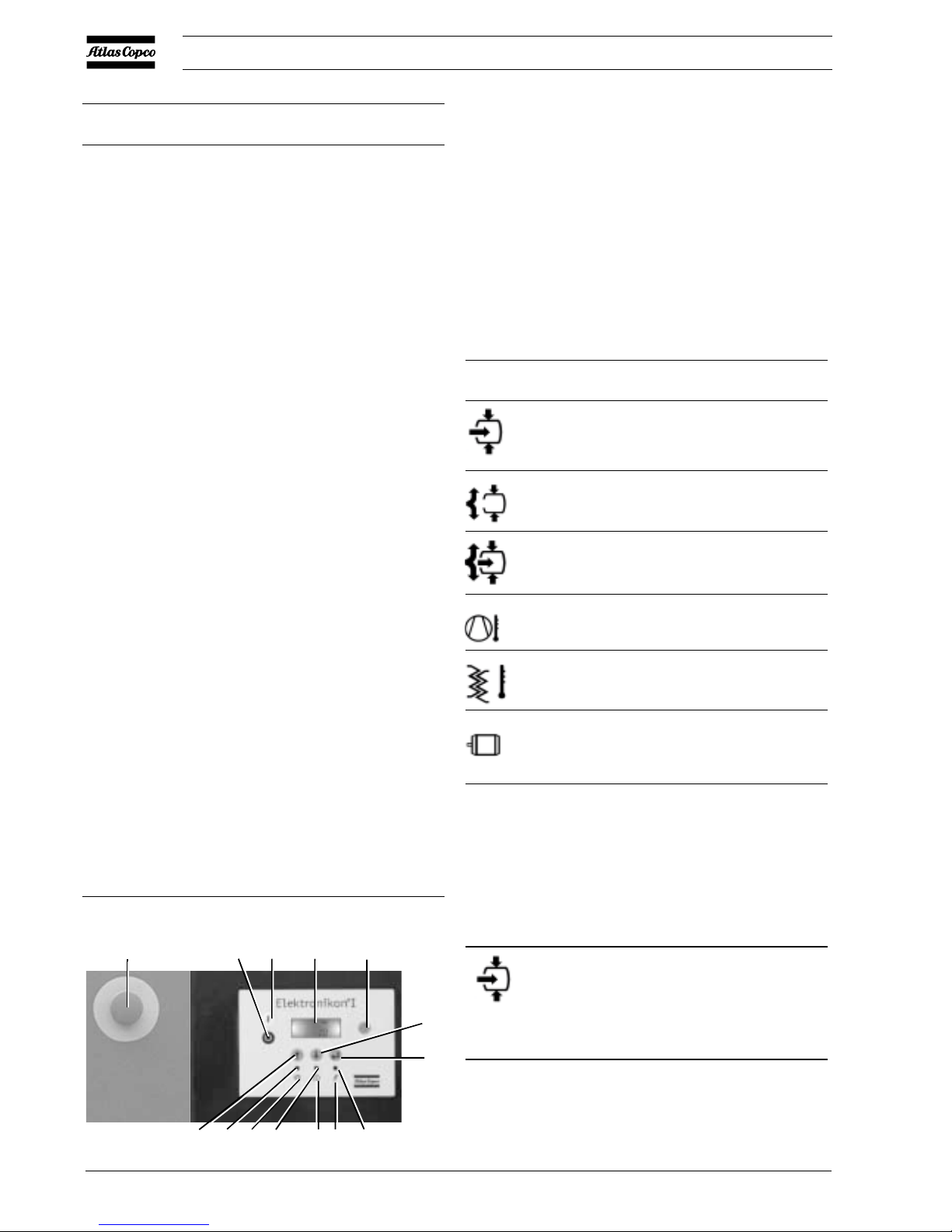
Control panel
10
11
8
9
7
6
3
21
4
5
12
13
52238F
S3
2920 1461 03
4
User manual
Ref. Designation Function
4 Reset key Key to reset the service timer, a
shut-down condition, etc.
5 Enter key Key to select or validate a
parameter, to open a sub-display
or to return to a previous display.
6 Voltage on LED Indicates that the voltage is
switched on.
7 Pictograph Voltage on
8 General alarm LED Is alight if a warning condition
exists.
8 General alarm LED Blinks in case of a shut-down or
emergency stop condition.
9 Pictograph Alarm
10 Automatic Indicates that the regulator is
operation LED automatically controlling the
compressor: the compressor is
loaded, unloaded, stopped and
restarted depending on the air
consumption and the limitations
programmed in the regulator.
11 Pictograph Automatic operation
12 Downwards Key to scroll downwards through
scroll key the screens or to decrease a setting.
13 Upwards scroll key Key to scroll upwards through the
screens or to increase a setting.
S3 Emergency stop Push button to stop the compressor
button immediately in case of emergency.
After remedying the trouble,
unlock the button by pulling it out
and press reset key 4.
3 Display
The display shows:
- the compressor operating status by means of pictographs
- the air outlet pressure
- the actual temperature at the compressor element outlet
- the actual dewpoint temperature (FF compressors)
The display also shows all measured and programmed
parameters, see section 7.
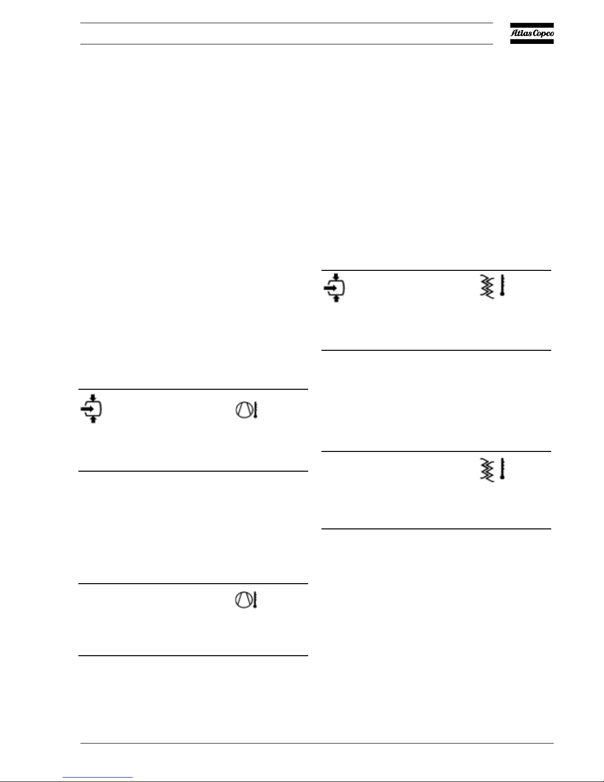
3.1 Pictographs used on the screen
Pictograph Explanation
Compressor status UNLOAD
Running hours
Element outlet temperature
Dewpoint temperature
Motor or motor overload
3.2 Main screen
When the voltage is switched on, the Main screen is shown
automatically, showing in short the operation status of the
compressor and the outlet pressure:
bar
6.8
Main screen, typical example
The screen shows that the compressor is running loaded (the
horizontal arrow blinks) and that the outlet pressure is 6.8 bar(e).
Compressor status LOAD (during loaded running,
the horizontal arrow blinks)
10
11
8
97 6
3
21
4
5
12
13
52236F
S3
2920 1461 03
5
User manual
Important
Always consult Atlas Copco in case "t" or "test" appears on the
display
3.3 Scrolling through all screens
It is possible to scroll downwards and upwards through a
number of screens by means of the upwards/downwards arrow
keys (12 and 13). See section 7.
4 Shut-down warning
A shut-down warning message will appear in case of:
- too high a temperature at the outlet of the compressor
element
- too high a dewpoint temperature (FF compressors)
4.1 Compressor element outlet temperature
1. In case the outlet temperature of the compressor element
exceeds the shut-down warning level (110 °C, not
programmable), alarm LED (8) will light up and the related
pictograph will appear blinking:
Blinking
bar
6.6
Warning screen, element outlet temperature
2. Press arrow key (12), r000 (register 000) appears.
3. Press arrow key (12), the actual compressor element
temperature appears:
Blinking
C
111
Warning screen, element outlet temperature
The screen shows that the temperature at the outlet of the
compressor element is 111 °C.
4. It remains possible to scroll through other screens (using
keys 12 and 13) to check the actual status of other
parameters.
5. Press button (1) to stop the compressor and wait until the
compressor has stopped.
6. Switch off the voltage, inspect the compressor and remedy.
7. The warning message will disappear as soon as the warning
condition disappears.
4.2 Dewpoint temperature
1. In case the dewpoint temperature exceeds the shut-down
warning level (programmable), alarm LED (8) will light up
and the related pictograph will appear blinking:
Blinking
bar
6.6
Warning screen, dewpoint temperature
2. Press arrow key (12), r000 (register 000) appears.
3. Press arrow key (12), the actual dewpoint temperature
appears:
Blinking
°C
9
Warning screen, dewpoint temperature
The screen shows that the dewpoint temperature is 9 °C.
4. It remains possible to scroll through other screens (using
keys 12 and 13) to check the actual status of other
parameters.
5. Press button (1) to stop the compressor and wait until the
compressor has stopped.
6. Switch off the voltage, inspect the compressor and remedy.
7. The warning message will disappear as soon as the warning
condition disappears.
2920 1461 03
6
User manual
5 Shut-down
The compressor will be shut down in case:
- the temperature at the outlet of the compressor element
exceeds the shut-down level
- of error of the outlet pressure sensor
- of overload of the drive motor and, on air-cooled
compressors, also the fan motor
5.1 Compressor element outlet temperature
1. In case the outlet temperature of the compressor element
exceeds the shut-down level (120 °C, not programmable),
the compressor will be shut down, alarm LED (8) will blink,
automatic operation LED (10) will go out and following
screen will appear:
Blinking
Shut-down screen, element outlet temperature
2. Press enter key (5), r000 (register 000) appears.
3. Press arrow key (12), the actual compressor element
temperature appears:
Blinking
°C
122
Shut-down screen, element outlet temperature
The screen shows that the temperature at the outlet of the
compressor element is 122 °C.
4. Switch off the voltage and remedy the trouble.
5. After remedying and when the shut-down condition has
disappeared, switch on the voltage and restart the
compressor.
5.2 Motor overload
1. In case of motor overload, the compressor will be shut down,
alarm LED (8) will blink, automatic operation LED (10)
will go out and following screen will appear:
Blinking
Shut-down screen, motor overload
2. Switch off the voltage and remedy the trouble.
3. After remedying and when the shut-down condition has
disappeared, switch on the voltage and restart the
compressor.
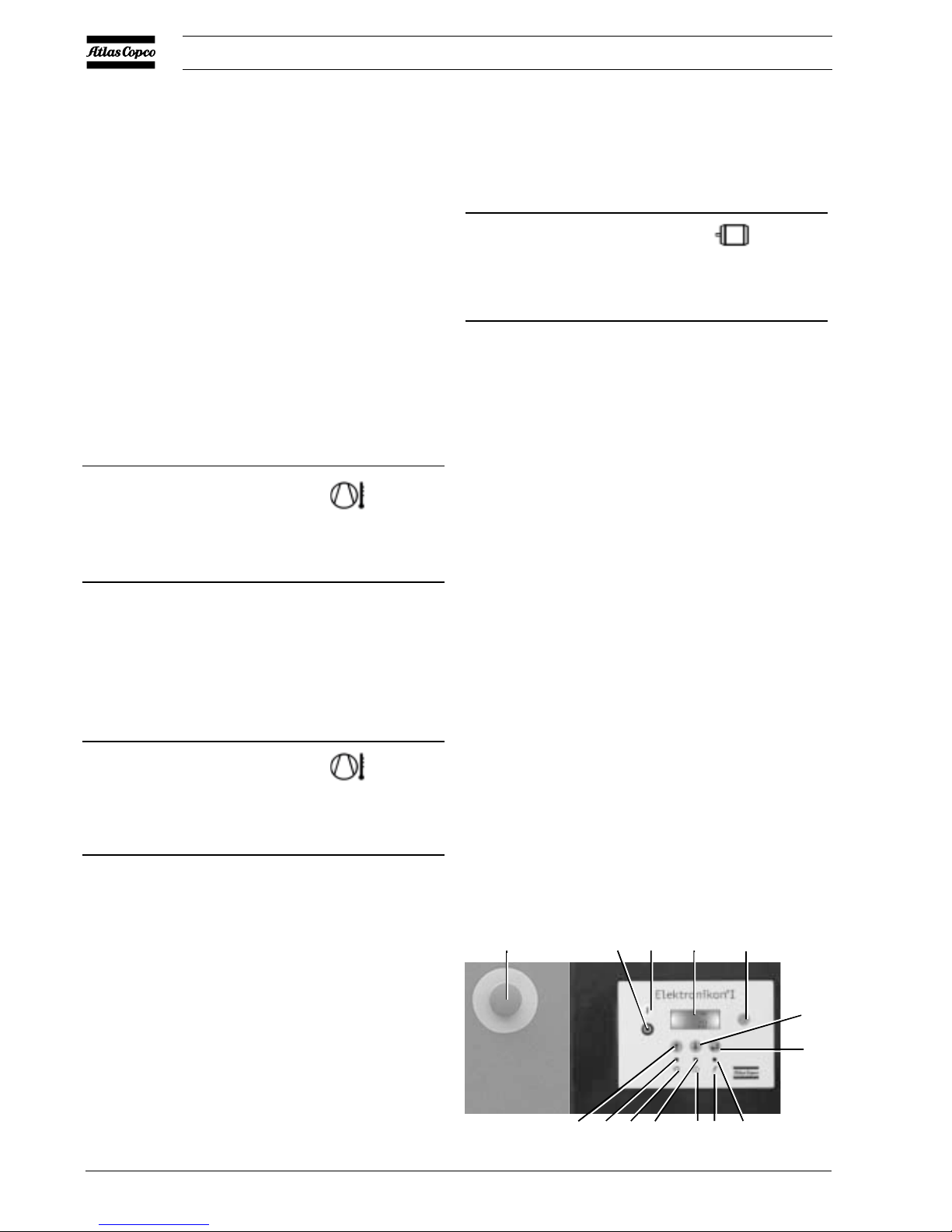
10
11
8
97 6
3
21
4
5
12
13
52236F
S3
2920 1461 03
7
User manual
6 Service warning
A service warning will appear when the service timer has
reached the programmed time interval.
1. In case the service timer exceeds the programmed time
interval, alarm LED (8) will light up.
2. Press arrow key (12): r000 is shown (register 000).
Press enter key (5), S (S standing for Service)
appears. Use key (12) to scroll to r005 (register 005)
and press enter key (5), the actual reading of the service
timer will be shown in kHrs (hours x 1000) .
Example: 4.002 indicates that the compressor has run for
4002 hours since previous service.
3. Press enter key (5) and key (12) to scroll to r001
(register 001). Press key (5) to check the running hours,
which are shown in kHrs (hours x 1000).
Example of running hours screen:
kHrs
8.000
The screen shows that the number of running hours is 8000.
4. Stop the compressor, switch off the voltage and carry
out the service actions as explained in the maintenance
schedule in the related Instruction book.
Important
- The longer interval service actions must include the
shorter interval actions.
In the example above, carry out all service operations
belonging to the 8000 running hours interval as well as
those belonging to the 4000 running hours interval.
- If using mineral oil instead of Atlas Copco Rotoinjectfluid, the service timer interval has to be decreased:
500 running hours for 13 bar (175 psi) units and 1000
running hours for 7.5-10 bar (100-150 psi) units.
5. After servicing, reset the service timer (see section 7.5).
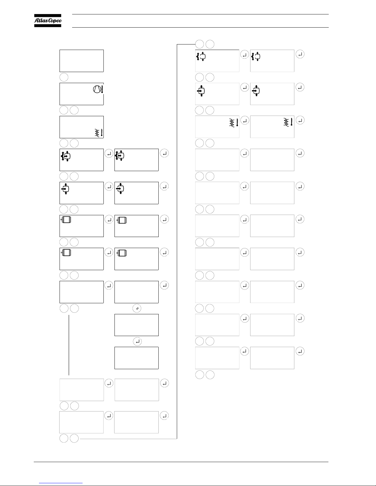
7 Scrolling through all screens
Scroll keys (12 and 13) can be used to scroll through all screens.
The screens are divided in register screens (numbered as r001,
r002,...) and parameter screens (numbered as P001,
P002,...).
During scrolling, the numbers of the screens appear consecutively.
For most screens, the unit of measurement and the related
pictograph are shown together with the screen number.
In case of a warning or shut-down, an extra register screen (r000)
is accessible.
Example:
kHrs
r001
The screen shows the screen number (r001), the unit used (kHrs
or hours x 1000) and the related pictograph for running hours.
Press enter key (5) to call up the actual running hours.
Overview of the screens
Register Show
screens
r001 Running hours (x1000 hrs)
r002 Loading hours (x1000 hrs)
r003 Motor starts (x1000)
r004 Motor starts (x1)
r005 Service timer reading
r006 Status of function "Automatic restart after voltage
failure"
r007 Programmed set of parameters
2920 1461 03
8
User manual
°C
82
°C
4
Bar
7.0
kHrs
r001
kHrs
4.039
r003
kHrs
3.161
3
158
kHrs
4.002
kHrs
"4.002"
r004
kHrs
r002
kHrs
r005
K
L
bar
P001
°C
P003
kHrs
P004
°C °F
P006
P007
P008
P009
P010
Bar
7.0
Bar
6.4
°C
8
kHrs
4.000
Mpa psi "bar"
"°C " °F
I
0000
"0"
0000
L
K
L
K
L
K
L
K
L
K
L
K
L
K
L
K
L
K
L
K
L
K
L
K
L
kHrs
0.000
K
L
K
L
bar
P002
K
L
K
L
Mpa psi bar
P005
K
L
52588PEN
K
L
K
L
r007
r006
1234
0
Simplified menu flow
2920 1461 03
9
User manual
Parameter Used for
screens
P001 Unload pressure setting
P002 Load pressure setting
P003 Warning level setting for dewpoint temperature
P004 Setting of service timer
P005 Setting of unit for pressure
P006 Setting of unit for temperature
P007 Selection between Y-D or DOL starting
P008 Selection for function "Automatic restart after
voltage failure" (active or not, only for Atlas
Copco)
P009 Selection between Local/Remote control
P010 Changing set of programmed parameters (only
for Atlas Copco)
7.1 Calling up outlet and dewpoint
temperatures
Starting from the Main screen:
bar
6.6
1. Press arrow key (12), the outlet temperature will be shown:
°C
83
The screen shows that the outlet temperature is 83 °C.
2. Press arrow key (12), the dewpoint temperature will be
shown:
°C
3
The screen shows that the dewpoint temperature is 3 °C.
3. Use keys (12 and 13) to scroll downwards or upwards
through the screens.
7.2 Calling up running hours
Starting from the Main screen:
bar
6.6
1. Press arrow key (12) until r001 is shown and then press
enter key (5):
kHrs
2.381
The screen shows the unit used (kHrs or hours x 1000) and
the value 2.381: the running hours of the compressor are 2381
hours.
7.3 Calling up loading hours
Starting from the Main screen:
bar
6.6
10
11
8
97 6
3
21
4
5
12
13
52236F
S3
2920 1461 03
10
User manual
1. Press arrow key (12) until r002 is shown and then press
enter key (5):
kHrs
1.755
The screen shows the unit used (kHrs or hours x 1000) and
the value 1.755: the loading hours of the compressor are 1755
hours.
7.4 Calling up motor starts
Starting from the Main screen:
bar
6.6
1. Press arrow key (12) until r003 is shown and then press
enter key (5):
3
This screen shows the number of motor starts times 1000. Press
enter key (5) to return to the register screens.
2. Press arrow key (12) until r004 is shown and then press
enter key (5):
226
This screen shows the number of motor starts to be added to
the reading in register r003. In this example, the number of
motor starts is 3226.
7.5 Calling up/resetting service timer
Starting from the Main screen:
bar
6.6
1. Press arrow key (12) until r005 is shown and then press
enter key (5):
kHrs
1.191
The screen shows the unit used (kHrs or hours x 1000) and
the value 1.191: the compressor has run for 1191 hours since
previous service.
Resetting the service timer
After servicing (see section 6), the timer has to be reset:
1. Scroll to register screen r005, the reading (e.g. 4.000)
will appear.
2. Press reset key (4), the reading will blink (indicating that
resetting is possible).
3. Press enter key (5) to reset the timer to "0.000" or press
reset key (4) to cancel the operation.
7.6 Automatic restart after voltage failure
Starting from the Main screen:
bar
6.6
Press arrow key (12) until r006 is shown and press enter key
(5):
- if 0 appears, the function Automatic restart after voltage
failure is not active
- if 1 appears, the function Automatic restart after voltage
failure is active
2920 1461 03
11
User manual
7.7 Set of parameters
Starting from the Main screen:
bar
6.6
Press arrow key (12) until r007 is shown and press enter key
(5): the number shown indicates the set of parameters which
are programmed ex-factory.
7.8 Calling up/modifying Unloading pressure
Starting from the Main screen:
bar
6.6
1. Press arrow key (12) until P001 is shown and press the
enter key (5):
bar
7.0
The screen shows the setting of the unloading pressure: 7.0
bar(e).
2. Use arrow keys (12 and 13) to modify this setting.
3. Press enter key (5) to program the new value and to return
to the parameter screens.
7.9 Calling up/modifying Loading pressure
Starting from the Main screen:
bar
6.6
1. Press arrow key (12) until P002 is shown and then press
enter key (5):
bar
6.4
The screen shows the setting of the loading pressure: 6.4 bar(e).
2. Use arrow keys (12 and 13) to modify this setting.
3. Press enter key (5) to program the new value and to return
to the parameter screens.
7.10 Calling up/modifying Dewpoint
warning temperature
Starting from the Main screen:
bar
6.6
10
11
8
97 6
3
21
4
5
12
13
52236F
S3
2920 1461 03
12
User manual
1. Press arrow key (12) until P003 is shown and press enter
key (5):
°C
8
The screen shows the warning setting for the dewpoint
temperature: 8 °C.
2. Use arrow keys (12 and 13) to modify this setting.
3. Press enter key (5) to program the new value and to return
to the parameter screens.
7.11 Calling up/modifying Service timer
setting
Starting from the Main screen:
bar
6.6
1. Press arrow key (12) until P004 is shown and then press
"enter" key (5): the setting of the service timer is shown in
"kHrs" (hours x 1000). Example: 4.000 means the timer
is set at 4000 running hours.
2. Use arrow keys (12 and 13) to modify this setting.
3. Press enter key (5) to program the new value and to return
to the parameter screens.
7.12 Calling up/modifying unit for pressure
Starting from the Main screen:
bar
6.6
1. Press arrow key (12) until P005 is shown and press enter
key (5): the possible settings are shown: MPa, psi and
bar; the actually used unit is blinking.
2. Use arrow keys (12 and 13) to select another unit for
pressure.
3. Press enter key (5) to program the new unit and to return to
the parameter screens.
7.13 Calling up/modifying unit for
temperature
Starting from the Main screen:
bar
6.6
1. Press arrow key (12) until P006 is shown and then press
enter key (5): the possible settings are shown: °C and
°F; the actually used unit is blinking.
2. Use arrow keys (12 and 13) to select another unit for
temperature.
3. Press enter key (5) to program the new unit and to return to
the parameter screens.
7.14 Selection between Y-D or DOL starting
Starting from the Main screen:
bar
6.6
10
11
8
97 6
3
21
4
5
12
13
52236F
S3
 Loading...