

Atlas Copco SF 15+, SF 17+, SF 22+, SFD 11+, SFD 15+ Instruction Book
...
INSTRUCTION BOOK
OIL-FREE SCROLL COMPRESSORS
SF 15+, SF 17+, SF 22+, SFD 11+, SFD 15+, SFD 22+


Atlas Copco
Oil-free scroll compressors
SF 15+, SF 17+, SF 22+, SFD 11+, SFD 15+, SFD 22+
From following serial No. onwards: API 770 000
Instruction book
Original instructions
COPYRIGHT NOTICE
Any unauthorized use or copying of the contents or any part thereof is prohibited.
This applies in particular to trademarks, model denominations, part numbers and
drawings.
This instruction book is valid for CE as well as non-CE labelled machines. It meets the
requirements for instructions specified by the applicable European directives as
identified in the Declaration of Conformity.
2017 - 06
No. 2920 7140 52
www.atlascopco.com

Table of contents
1 Safety precautions..........................................................................................................5
1.1 SAFETY ICONS...................................................................................................................................
5
1.2 SAFETY PRECAUTIONS, GENERAL...........................................................................................................5
1.3 SAFETY PRECAUTIONS DURING INSTALLATION...........................................................................................6
1.4 SAFETY PRECAUTIONS DURING OPERATION..............................................................................................7
1.5 SAFETY PRECAUTIONS DURING MAINTENANCE OR REPAIR........................................................................... 8
2 General description......................................................................................................10
2.1 GENERAL DESCRIPTION..................................................................................................................... 10
2.2 FLOW DIAGRAM................................................................................................................................14
2.3 REGULATING SYSTEM........................................................................................................................18
2.4 ELECTRICAL SYSTEM.........................................................................................................................
19
2.5 ELECTRIC DIAGRAM...........................................................................................................................
20
2.6 TEMPERATURE PROTECTION............................................................................................................... 20
2.7 AIR DRYER......................................................................................................................................22
3 Controller.......................................................................................................................24
3.1 GENERAL........................................................................................................................................24
3.2 CONTROL PANEL.............................................................................................................................. 26
3.3 ICONS USED.................................................................................................................................... 27
3.4 MAIN SCREEN..................................................................................................................................30
3.5 CALLING UP MENUS.......................................................................................................................... 34
3.6 SHUTDOWN WARNING........................................................................................................................
35
3.7 SHUTDOWN.....................................................................................................................................39
3.8 INPUTS MENU...................................................................................................................................39
3.9 OUTPUTS MENU............................................................................................................................... 42
3.10 COUNTERS......................................................................................................................................43
3.11 CONTROL MODE SELECTION................................................................................................................44
Instruction book
2 2920 7140 52

3.12 SERVICE MENU................................................................................................................................
45
3.13 SETPOINT MENU...............................................................................................................................49
3.14 EVENT HISTORY MENU.......................................................................................................................51
3.15 GENERAL SETTINGS MENU..................................................................................................................52
3.16 INFO MENU......................................................................................................................................54
3.17 WEEK TIMER MENU...........................................................................................................................54
3.18 TEST MENU.....................................................................................................................................62
3.19 USER PASSWORD MENU.....................................................................................................................63
3.20 WEB SERVER.................................................................................................................................. 64
3.21 PROGRAMMABLE SETTINGS.................................................................................................................73
4 Installation guidelines..................................................................................................76
4.1 DIMENSION DRAWING........................................................................................................................ 76
4.2 INSTALLATION PROPOSAL................................................................................................................... 76
4.3 ELECTRICAL CONNECTIONS.................................................................................................................78
4.4 PICTOGRAPHS................................................................................................................................. 80
5 Operating instructions................................................................................................. 81
5.1 INITIAL START-UP..............................................................................................................................81
5.2 STARTING.......................................................................................................................................81
5.3 DURING OPERATION..........................................................................................................................82
5.4 STOPPING.......................................................................................................................................83
5.5 TAKING OUT OF OPERATION................................................................................................................
83
6 Maintenance..................................................................................................................84
6.1 PREVENTIVE MAINTENANCE SCHEDULE..................................................................................................84
6.2 SERVICE KITS.................................................................................................................................. 86
6.3 DISPOSAL OF USED MATERIAL.............................................................................................................86
Instruction book
2920 7140 52 3

7 Adjustments and servicing procedures..................................................................... 88
7.1 AIR FILTER......................................................................................................................................
88
7.2 AIR COOLER....................................................................................................................................88
7.3 DRIVE MOTOR..................................................................................................................................88
7.4 SAFETY VALVE.................................................................................................................................89
7.5 BELT SET EXCHANGE AND TENSIONING................................................................................................. 89
7.6 CLEANING THE COMPRESSOR ELEMENT.................................................................................................90
7.7 REPLACEMENT OF THE OUTLET PIPE.....................................................................................................91
7.8 DRYER MAINTENANCE........................................................................................................................92
8 Problem solving............................................................................................................94
9 Technical data...............................................................................................................96
9.1 ELECTRIC CABLE SIZE AND FUSES........................................................................................................96
9.2 REFERENCE CONDITIONS AND LIMITATIONS.......................................................................................... 102
9.3 COMPRESSOR DATA........................................................................................................................103
10 Guidelines for inspection...........................................................................................107
11 PED (Pressure Equipment Directive)........................................................................108
12 Declaration of conformity.......................................................................................... 109
Instruction book
4 2920 7140 52
1 Safety precautions
1.1
Safety icons
Explanation
Danger to life
Warning
Important note
1.2 Safety precautions, general
General precautions
1.
The operator must employ safe working practices and observe all related work safety
requirements and regulations.
2. If any of the following statements does not comply with the applicable legislation, the stricter
of the two shall apply.
3. Installation, operation, maintenance and repair work must only be performed by authorized,
trained, specialized personnel.
4. Never use compressed air as breathing air without prior purification in accordance with local
legislation and standards.
5. Before any maintenance, repair work, adjustment or any other non-routine checks, stop the
compressor, press the emergency stop button, switch off the voltage and depressurize the
compressor. In addition, the power isolating switch must be opened and locked.
6. Never play with compressed air. Do not apply the air to your skin or direct an air stream at
people. Never use the air to clean dirt from your clothes. When using the air to clean
equipment, do so with extreme caution and wear eye protection.
7. The owner is responsible for maintaining the unit in safe operating condition. Parts and
accessories shall be replaced if unsuitable for safe operation.
8. It is not allowed to walk or stand on the compressor or its components.
Instruction book
2920 7140 52 5

1.3 Safety precautions during installation
All responsibility for any damage or injury resulting from neglecting these precautions, or
non observance of the normal caution and care required for installation, operation,
maintenance and repair, even if not expressly stated, will be disclaimed by the
manufacturer.
These precautions apply to machinery processing or consuming air or inert gas.
Processing of any other gas requires additional safety precautions typical to the
application which are not included herein.
Some precautions are general and cover several machine types and equipment; hence
some statements may not apply to your machine.
Precautions during installation
1.
The machine must only be lifted using suitable equipment in accordance with local safety
regulations. Loose or pivoting parts must be securely fastened before lifting. It is strictly
forbidden to dwell or stay in the risk zone under a lifted load. Lifting acceleration and
deceleration must be kept within safe limits. Wear a safety helmet when working in the area
of overhead or lifting equipment.
2. Place the machine where the ambient air is as cool and clean as possible. If necessary,
install a suction duct. Never obstruct the air inlet. Care must be taken to minimise the entry
of moisture at the inlet air. Consult section Reference conditions and limitations.
3. Any blanking flanges, plugs, caps and desiccant bags must be removed before connecting
the pipes.
4. Air hoses must be of correct size and suitable for the working pressure. Never use frayed,
damaged or worn hoses. Distribution pipes and connections must be of the correct size and
suitable for the working pressure.
5. The aspirated air must be free of flammable fumes, vapours and particles, e.g. paint
solvents, that can lead to internal fire or explosion.
6. Arrange the air intake so that loose clothing worn by people cannot be sucked in.
7. Ensure that the discharge pipe from the compressor to the aftercooler or air net is free to
expand under heat and that it is not in contact with or close to flammable materials.
8. No external force may be exerted on the air outlet valve. The connected pipe must be free of
strain.
9. If remote control is installed, the machine must bear a clear sign stating "DANGER: This
machine is remotely controlled and may start without warning".
The operator has to make sure that the machine is stopped and that the isolating switch is
open and locked before any maintenance or repair. As a further safeguard, persons
switching on remotely controlled machines shall take adequate precautions to ensure that
there is no one checking or working on the machine. To this end, a suitable notice shall be
affixed to the start equipment.
10. Air-cooled machines must be installed in such a way that an adequate flow of cooling air is
available and that the exhausted air does not recirculate to the compressor air inlet or
cooling air inlet.
11. The electrical connections must correspond to the applicable codes. The machines must be
earthed and protected against short circuits by fuses in all phases. A lockable power
isolating switch must be installed near the compressor.
12. On machines with automatic start-stop system or if the automatic restart function after
voltage failure is activated, a sign stating "This machine may start without warning" must be
affixed near the instrument panel.
Instruction book
6 2920 7140 52
13. In multiple compressor systems, manual valves must be installed to isolate each
compressor. Non-return valves (check valves) must not be relied upon for isolating pressure
systems.
14.
Never remove or tamper with the safety devices, guards or insulation fitted on the machine.
Every pressure vessel or auxiliary installed outside the machine to contain air above
atmospheric pressure must be protected by a pressure relieving device or devices as
required.
15. Piping or other parts with a temperature in excess of 80˚C (176˚F) and which may be
accidentally touched by personnel in normal operation must be guarded or insulated. Other
high temperature piping must be clearly marked.
16. For water-cooled machines, the cooling water system installed outside the machine has to
be protected by a safety device with set pressure according to the maximum cooling water
inlet pressure.
17. If the ground is not level or can be subject to variable inclination, consult the manufacturer.
Also consult following safety precautions: Safety precautions during operation and
Safety precautions during maintenance.
1.4 Safety precautions during operation
All responsibility for any damage or injury resulting from neglecting these precautions, or
non observance of the normal caution and care required for installation, operation,
maintenance and repair, even if not expressly stated, will be disclaimed by the
manufacturer.
These precautions apply to machinery processing or consuming air or inert gas.
Processing of any other gas requires additional safety precautions typical to the
application which are not included herein.
Some precautions are general and cover several machine types and equipment; hence
some statements may not apply to your machine.
Precautions during operation
1.
Never touch any piping or components of the compressor during operation.
2. Use only the correct type and size of hose end fittings and connections. When blowing
through a hose or air line, ensure that the open end is held securely. A free end will whip
and may cause injury. Make sure that a hose is fully depressurized before disconnecting it.
3. Persons switching on remotely controlled machines shall take adequate precautions to
ensure that there is no one checking or working on the machine. To this end, a suitable
notice shall be affixed to the remote start equipment.
4. Never operate the machine when there is a possibility of taking in flammable or toxic fumes,
vapors or particles.
5. Never operate the machine below or in excess of its limit ratings.
6. Keep all bodywork doors shut during operation. The doors may be opened for short periods
only, e.g. to carry out routine checks. Wear ear protectors when opening a door.
7. People staying in environments or rooms where the sound pressure level reaches or
exceeds 90 dB(A) shall wear ear protectors.
8. Periodically check that:
• All guards are in place and securely fastened
• All hoses and/or pipes inside the machine are in good condition, secure and not
rubbing
Instruction book
2920 7140 52 7
• There are no leaks
•
All fasteners are tight
• All electrical leads are secure and in good order
• Safety valves and other pressure relief devices are not obstructed by dirt or paint
• Air outlet valve and air net, i.e. pipes, couplings, manifolds, valves, hoses, etc. are in
good repair, free of wear or abuse
9. If warm cooling air from compressors is used in air heating systems, e.g. to warm up a
working area, take precautions against air pollution and possible contamination of the
breathing air.
10. Do not remove any of, or tamper with, the sound dampening material.
11. Never remove or tamper with the safety devices, guards or insulation fitted to the machine.
Every pressure vessel or auxiliary installed outside the machine to contain air above
atmospheric pressure shall be protected by a pressure relieving device or devices as
required.
12. Be aware of possible blow off of safety valves during operation. For the location of the safety
valves, consult the description in this instruction book.
13. Yearly inspect the air receiver. Minimum wall thickness as specified in the instruction book
must be respected. Local regulations remain applicable if they are more strict.
Also consult following safety precautions: Safety precautions during installation and
Safety precautions during maintenance.
1.5 Safety precautions during maintenance or repair
All responsibility for any damage or injury resulting from neglecting these precautions, or
non observance of the normal caution and care required for installation, operation,
maintenance and repair, even if not expressly stated, will be disclaimed by the
manufacturer.
These precautions apply to machinery processing or consuming air or inert gas.
Processing of any other gas requires additional safety precautions typical to the
application which are not included herein.
Some precautions are general and cover several machine types and equipment; hence
some statements may not apply to your machine.
Precautions during maintenance or repair
1.
Always use the correct safety equipment such as safety glasses, gloves, safety shoes, etc.
2. Use only the correct tools for maintenance and repair work.
3. Use only genuine spare parts.
4. All maintenance work shall only be undertaken when the machine has cooled down.
5. A warning sign bearing a legend such as "Work in progress; do not start" shall be attached
to the starting equipment.
6. Persons switching on remotely controlled machines shall take adequate precautions to
ensure that there is no one checking or working on the machine. To this end, a suitable
notice shall be affixed to the remote start equipment.
7. Close the compressor air outlet valve before connecting or disconnecting a pipe.
8. Before removing any pressurized component, effectively isolate the machine from all
sources of pressure and relieve the entire system of pressure.
9. Never use flammable solvents or carbon tetrachloride for cleaning parts. Take safety
precautions against toxic vapours of cleaning liquids.
Instruction book
8 2920 7140 52

10. Scrupulously observe cleanliness during maintenance and repair. Keep dirt away by
covering the parts and exposed openings with a clean cloth, paper or tape.
11.
Never weld or perform any operation involving heat near any oil system. Oil tanks must be
completely purged, e.g. by steam-cleaning, before carrying out such operations. Never weld
on, or in any way modify, pressure vessels.
12. Whenever there is an indication or any suspicion that an internal part of a machine is
overheated, the machine shall be stopped but no inspection covers shall be opened before
sufficient cooling time has elapsed to avoid spontaneous ignition of the oil vapour (if
applicable) when air is admitted.
13. Never use a light source with open flame for inspecting the interior of a machine, pressure
vessel, etc.
14. Make sure that no tools, loose parts or rags are left in or on the machine.
15. All regulating and safety devices shall be maintained with due care to ensure that they
function properly. They may not be put out of action.
16. Before clearing the machine for use after maintenance or overhaul, check that operating
pressures, temperatures and time settings are correct. Check that all control and shut-down
devices are fitted and that they function correctly. If removed, check that the coupling guard
of the compressor drive shaft has been reinstalled.
17. Protect the motor, air filter, electrical and regulating components, etc. to prevent moisture
from entering them, e.g. when steam-cleaning.
18. Make sure that all sound-damping material, e.g. on the bodywork and in the air inlet and
outlet systems of the compressor, is in good condition. If damaged, replace it by genuine
material from the manufacturer to prevent the sound pressure level from increasing.
19. Never use caustic solvents which can damage materials of the air net, e.g. polycarbonate
bowls.
20. The following safety precautions are stressed when handling refrigerant:
• Never inhale refrigerant vapours. Check that the working area is adequately ventilated;
if required, use breathing protection.
• Always wear special gloves. In case of refrigerant contact with the skin, rinse the skin
with water. If liquid refrigerant contacts the skin through clothing, never tear off or
remove the latter; flush abundantly with fresh water over the clothing until all refrigerant
is flushed away; then seek medical first aid.
21. Protect hands to avoid injury from hot machine parts, e.g. during draining of oil.
22. Be aware of eventual sharp edges on certain parts of the machine.
Also consult following safety precautions: Safety precautions during installation
and
Safety precautions during operation.
Instruction book
2920 7140 52 9

2 General description
2.1
General description
Introduction
SF 15+, SF 17+ and SF 22+ are stationary, oil free compressors.
Dependent on the model, the compressors have 3 or 4 electric motor driven compressor
modules, enclosed in a sound insulating canopy. The front door panel houses the Elektronikon
Graphic controller and the emergency stop button. An electric cabinet with the electric
components is installed behind the front panel. The compressors can be delivered with or without
integrated refrigerant air dryer.
SFD 11+, SFD 15+ and SFD 22+ are stationary, oil free compressors. They have a duplex setup
of the compressor compartment, existing of 1 or 2 active compressor modules and 1 or 2
compressor modules as backup, enclosed in a common sound insulating canopy. The front door
panel of each set of compressor modules houses the Elektronikon Graphic controller and the
emergency stop button. An electric cabinet with the electric components is located behind the
front panel of each module. SFD have no integrated air dryer.
SF
SF is the type designation of the compressor variant without integrated dryer. On SF, the
compressed air of each compressor module flows via an individual check valve to a common air
cooler and leaves the compressor via the air outlet valve.
SF Full Feature (SF FF) compressors are SF compressors provided with a refrigerant air dryer,
integrated in the bodywork. The dryer removes moisture from the compressed air by cooling the
air to near freezing point and automatically draining the condensate.
SF 22+ FF, front view
1 Elektronikon Graphic controller S3 Emergency stop button
2 Electric cabinet DR Refrigerant dryer
Instruction book
10 2920 7140 52
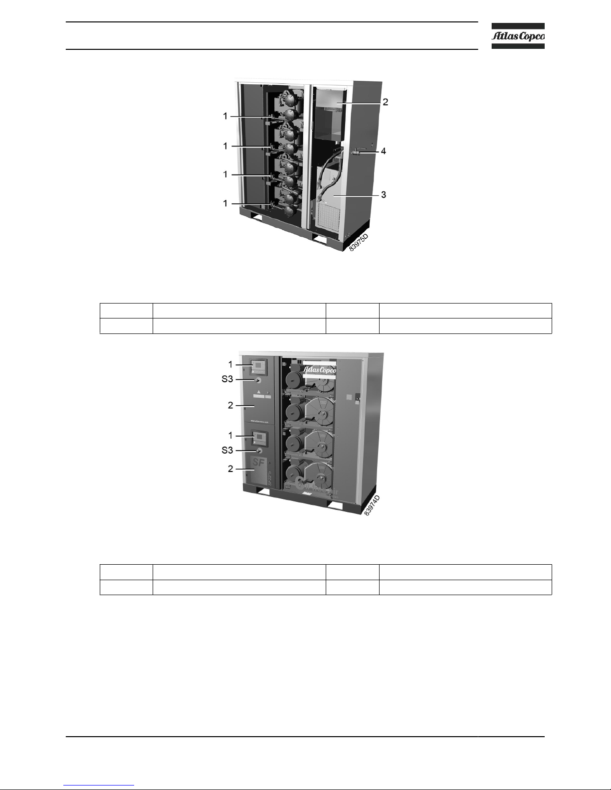
SF 22+ FF, rear view
1 Compressor module 3 Refrigerant dryer
2 Air cooler 4 Compressed air outlet valve
SFD 22+, front view
1 Elektronikon Graphic controller S3 Emergency stop button
2 Electric cabinet
Compressor element operating principle
Each compressor element consists of a fixed scroll shaped housing and a scroll shaped rotor. Air
enters the compressor element through inlet opening (1). Once the air is drawn in, the orbiting
scroll (4) seals the inlet opening and forces the air into a continuously decreasing space. As scroll
(4) keeps orbiting, this process of compression is constantly repeated, resulting in discharging of
oil free compressed air through outlet opening (3).
Instruction book
2920 7140 52 11

Compressor element, typical
1 Air inlet 3 Air outlet
2 Fixed scroll 4 Orbiting scroll
Compressor module
The SF 15+
has four 3.7 kW modules, while the SF 17+ and the SF 22+ respectively have three or
four 5.5 kW modules.
The SFD 15+ has four 3.7 kW modules, while the SFD 11+ and the SFD 22+ respectively have
two or four 5.5 kW modules.
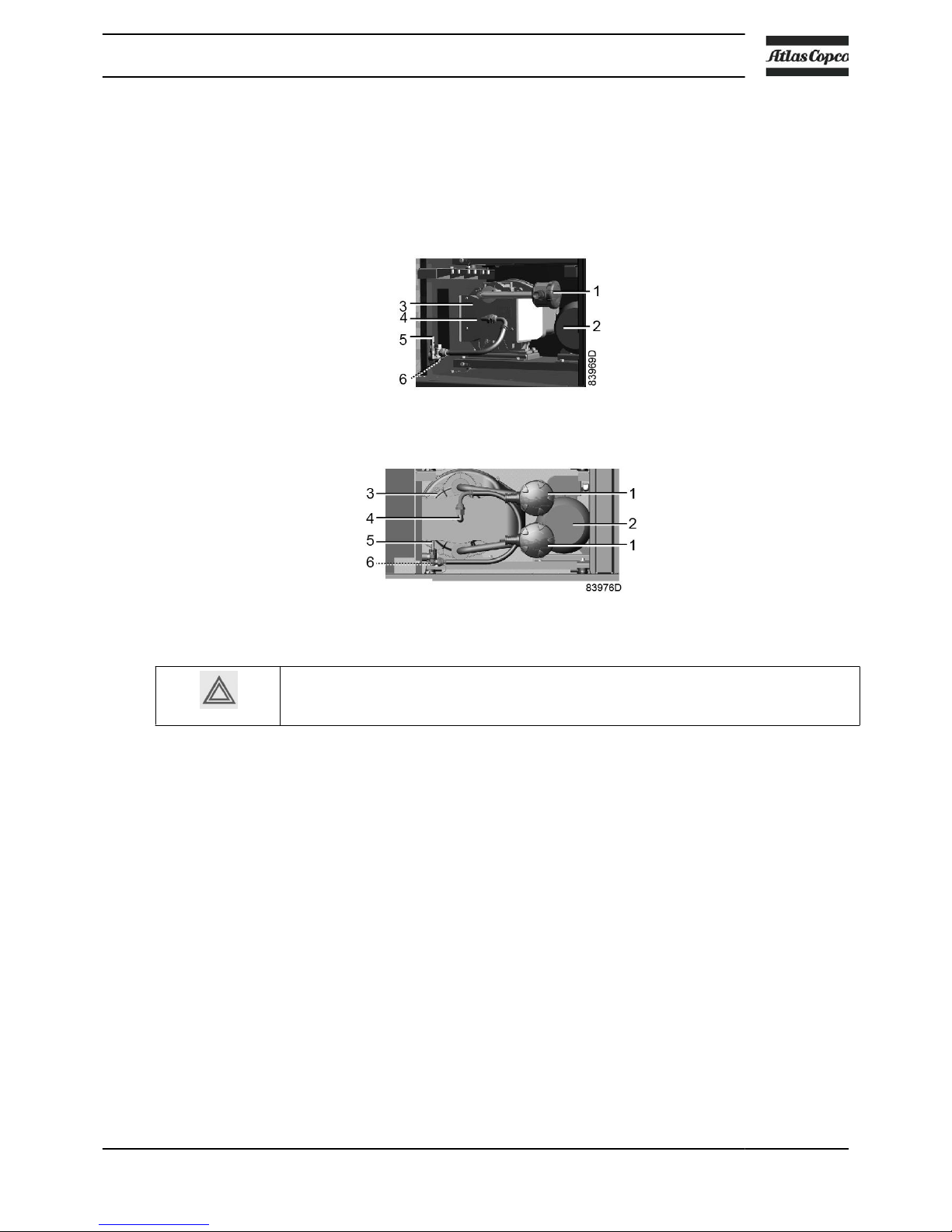
3.7 kW compressor module
5.5 kW compressor module
Instruction book
12 2920 7140 52

1 Air filter 4 Compressor element air outlet
2 Motor 5 Safety valve
3 Compressor element 6 Temperature sensor
Instruction book
2920 7140 52 13
2.2 Flow diagram
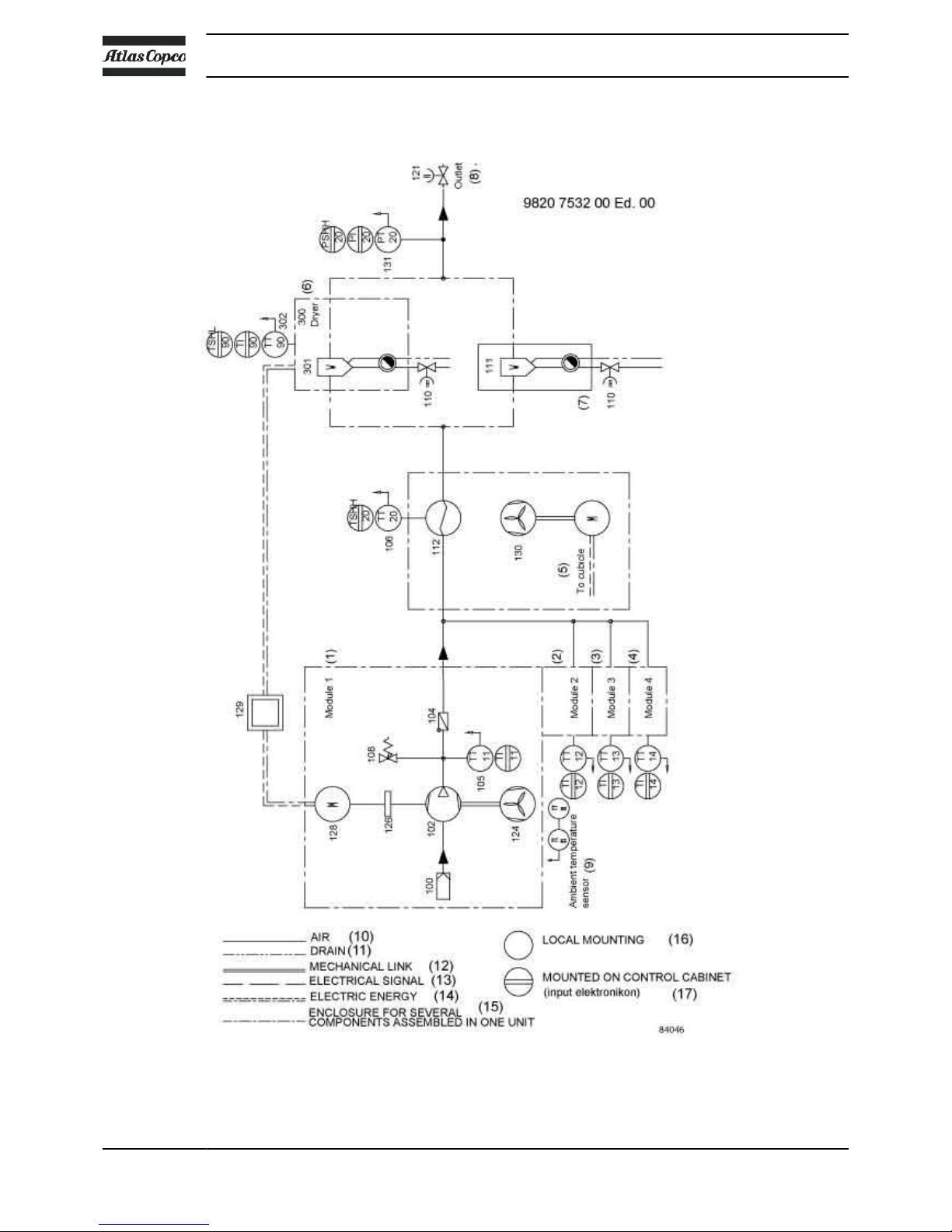
Flow diagram of SF 15+, SF 17+, SF 22
+
Instruction book
14 2920 7140 52

Text on image
(1) Compressor module 1 (10) Air
(2) Compressor module 2 (11) Drain
(3) Compressor module 3 (12) Mechanical link
(4) Compressor module 4 (13) Electrical signal
(5) To cubicle (14) Electric energy
(6) Refrigerant dryer (units with dryer) (15) Enclosure
(7) Water separator (units without dryer) (16) Local mounting
(8) Outlet (17) On control cabinet
(9) Ambient temperature sensor
Instruction book
2920 7140 52 15
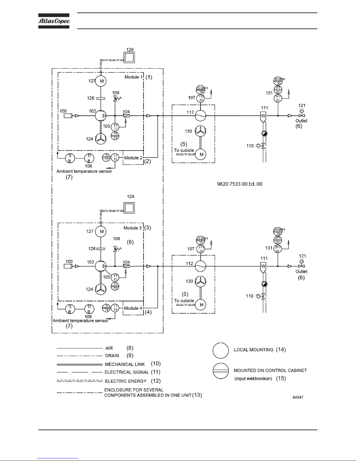
Flow diagram of SFD 11+, SFD 15+, SFD 22
+
Instruction book
16 2920 7140 52
Text on image
(1) Compressor module 1 (9) Drain
(2) Compressor module 2 (10) Mechanical link
(3) Compressor module 3 (11) Electrical signal
(4) Compressor module 4 (12) Electric energy
(5) To cubicle (13) Enclosure
(6) Outlet (14) Local mounting
(7) Ambient temperature sensor (15) On control cabinet
(8) Air
Air flow
Air is drawn through air filter (100) and is compressed by the compressor element (102) of each
compressor module. The compressed air is discharged via the check valve (104) and a common
air cooler (112).
On compressors without integrated dryer, the compressed air passes a water separator (111)
and flows to the outlet valve (121).
On standard compressors with an integrated air dryer, the compressed air flows through a
common refrigerant dryer (300) before reaching the outlet valve (121). For details on the
operation of the dryer, see section Refrigerant dryer.
Cooling
Each compressor element (102) is cooled by a radial fan (124), mounted on the drive shaft of the
compressor element. The cooling air is blown over the compressor element via a duct.
A separate electric fan (130) provides cooling air for the common air cooler (112).
On SFD compressors, each set of compressor modules has its own common aftercooler with an
electric fan.
Condensate management
The water separator (111) on compressors without integrated dryer has an automatic condensate
outlet and a manual drain valve.
On compressors with integrated dryer, the dryer is equipped with a water trap with an automatic
condensate outlet and a manual drain valve.
Instruction book
2920 7140 52 17
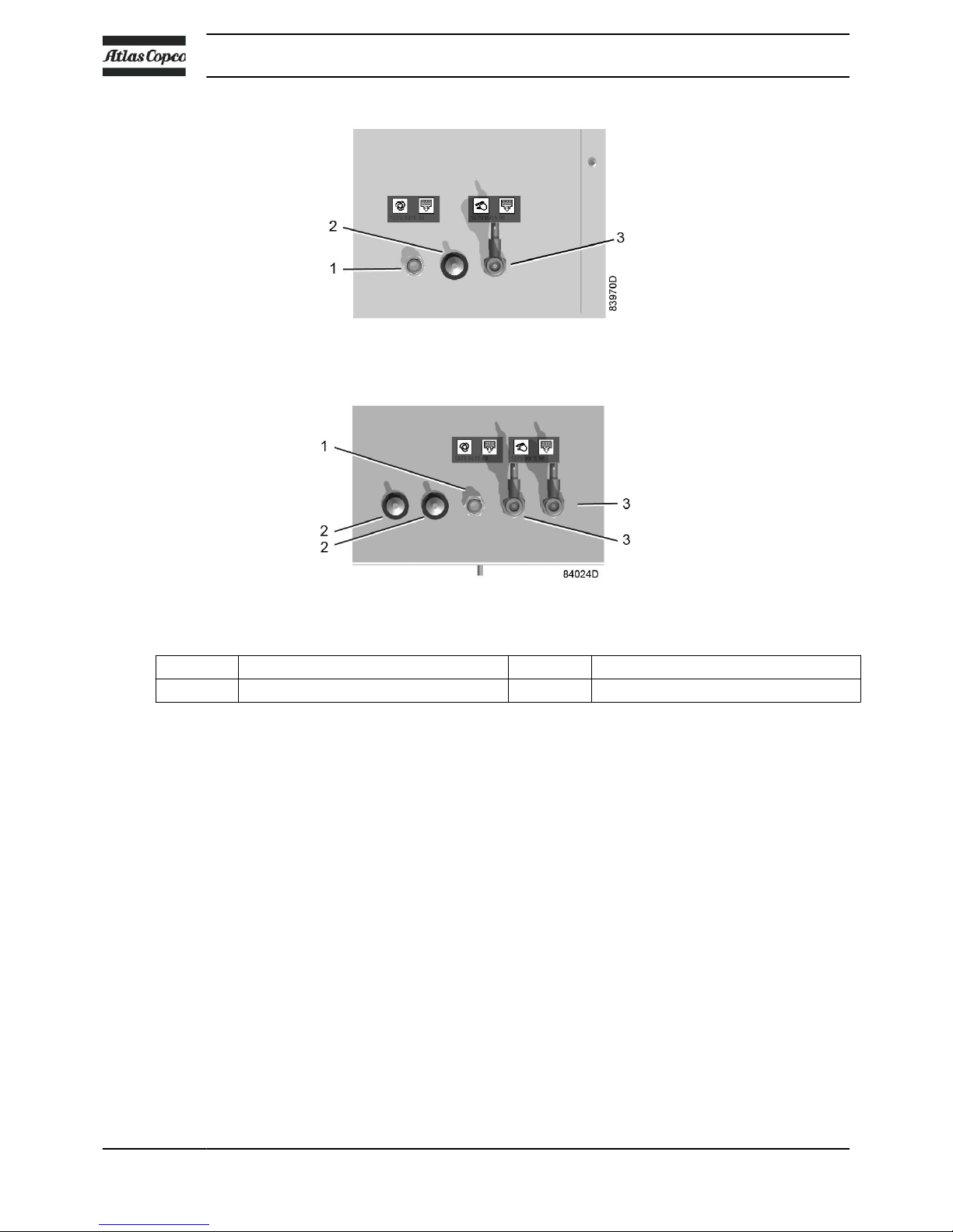
Condensate drain connections (typical)
Condensate drain connections on SFD
1 Automatic condensate drain outlet 3 Manual condensate drain valve
2 Ambient temperature sensor
2.3 Regulating system
The compressor is provided with an Elektronikon® controller module.
The controller performs following functions:
• Monitoring the pressure
• Protecting the compressor
• Monitoring components subject to service
• Automatic restart after voltage failure
For more details, please consult the sections on the controller further in this book.
Instruction book
18 2920 7140 52
2.4 Electrical system
Cubicle layout
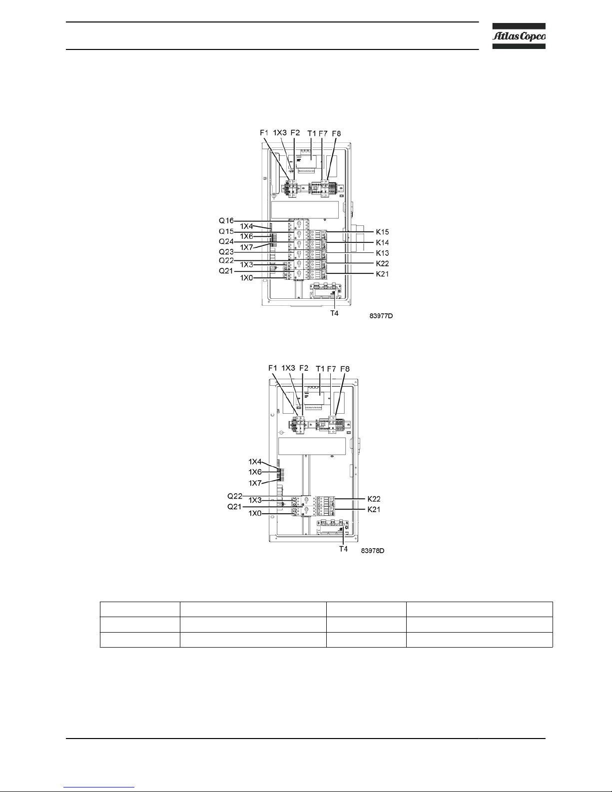
Electrical cabinet SF 15+, SF 17+ and SF 22+, typical
Electrical cabinet SFD 11+, SFD 15+ and SFD 22+, typical
K21, K22,... Contactor 1X0, 4X3,... Terminals
Q21,Q22,... Circuit breaker T1, T4,... Transformer
F1,F2,... Fuses
Instruction book
2920 7140 52 19
2.5 Electric diagram
• The electrical installation must correspond to the applicable codes.
•
The mains supply and earthing lines must be of suitable size. See section Electric
cable size and fuses.
• The installation must be earthed and protected by fuses in each phase.
• An isolating switch must be installed near the compressor. Make sure that this
switch is open to isolate the compressor from the mains before carrying out any
connection.
The complete electrical diagram is available in the electric cubicle of the compressor. For
connection of the supply wires, please see section Electrical connections.
2.6
Temperature protection
The compressor is equipped with an ambient temperature sensor. The sensor creates a warning
message on the controller if the ambient temperature rises above 40 °C (104 °F). If the ambient
temperature reaches 45 °C (113 °F), the compressor is stopped.
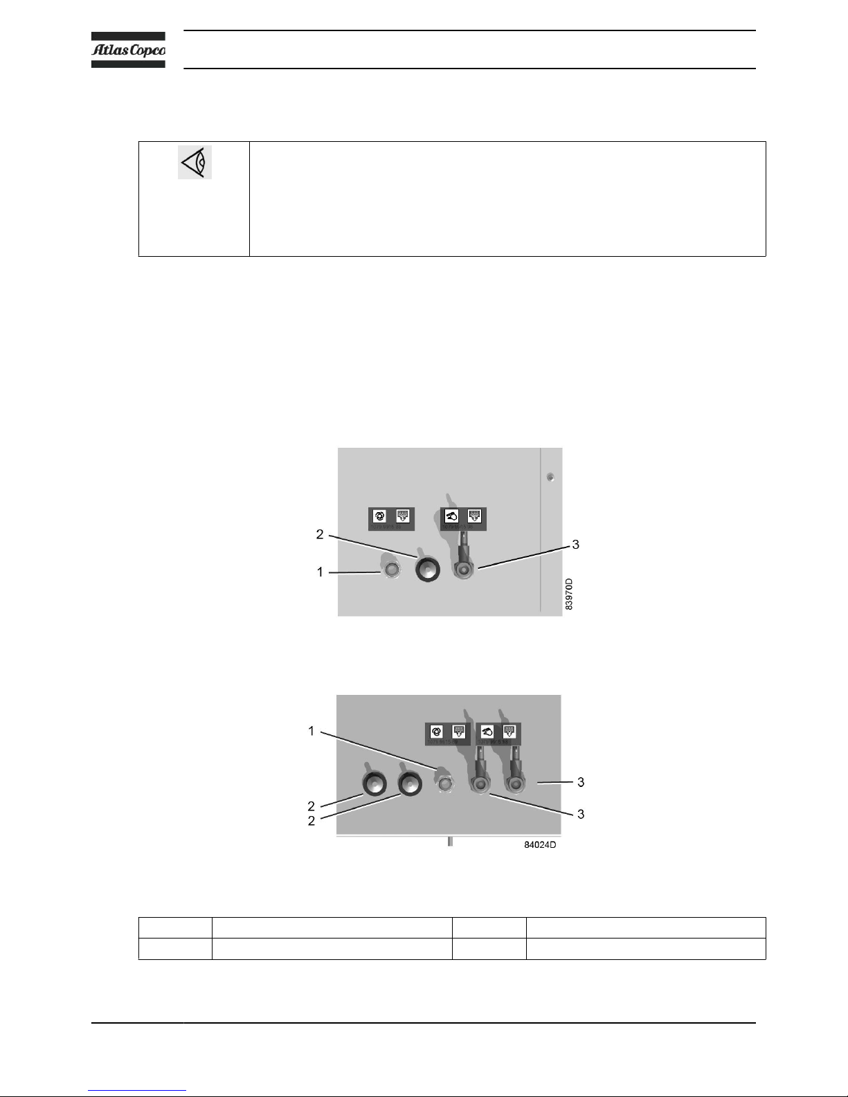
Condensate drain connections
Condensate drain connections on SFD
1 Automatic condensate drain outlet 3 Manual condensate drain valve
2 Ambient temperature sensor
Instruction book
20 2920 7140 52
Each compressor element is protected by a PT 1000 sensor (6) in the outlet pipe. The sensor is
connected to the electronic regulator.
When the maximum temperature is exceeded, the compressor element is stopped during 2
minutes before it can restart. If this happens 2 times within a time span of 2 hours, the element
will be stopped during 10 minutes. If the compressor element stops a third time within the 2 hours
time span, the element will be shut down and must be reset manually.
3.7 kW compressor module
5.5 kW compressor module
When the compressor is stopped due to overheating, the compressor will not restart
until the failure is acknowledged and the compressor is restarted manually. See also
sections Shutdown warning and Shutdown.
Instruction book
2920 7140 52 21
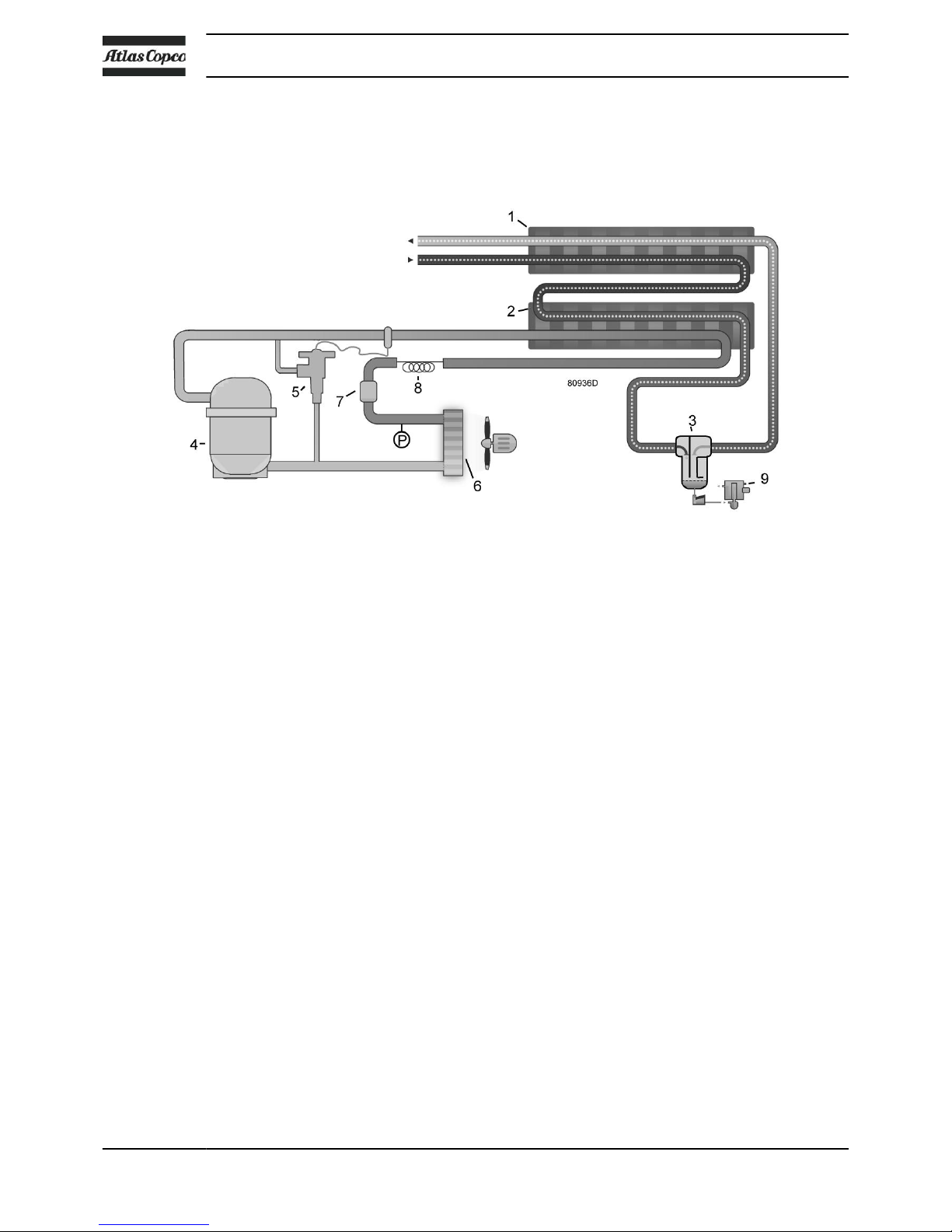
2.7 Air dryer
Flow diagram
Compressed air circuit
Compressed air enters heat exchanger (1) and is cooled by the outgoing, cold, dried air. Water in
the incoming air starts to condense. The air then flows through heat exchanger/evaporator (2)
where the refrigerant evaporates, causing the air to be cooled further to close to the evaporating
temperature of the refrigerant. More water in the air condenses. The cold air then flows through
separator (3) where all the condensate is separated from the air.
The cold, dried air flows through heat exchanger (1) where it is warmed up by the incoming air.
The condensate is automatically drained by the electronic condensate drain (9).
Refrigerant circuit
Compressor (4) delivers hot, high-pressure refrigerant gas which flows through condenser (6)
where most of the refrigerant condenses.
The liquid flows through liquid refrigerant dryer/filter (7) to capillary tube (8). The refrigerant
leaves the capillary tube at evaporating pressure.
The refrigerant enters evaporator (2) where it withdraws heat from the compressed air by further
evaporation at constant pressure. The heated refrigerant leaves the evaporator and is sucked in
by the compressor.
The condenser (6) pressure must be kept as constant as possible to obtain stable operation. Fan
control switch (P) therefore stops and starts the condenser cooling fan. If, under partial or no
load, the evaporator (2) pressure drops to approximately 2.25 bar(e) (32.63 psig), the hot gas
bypass valve (5) opens and hot, high-pressure gas is fed to the evaporator circuit to prevent the
evaporator pressure from dropping any further.
Instruction book
22 2920 7140 52
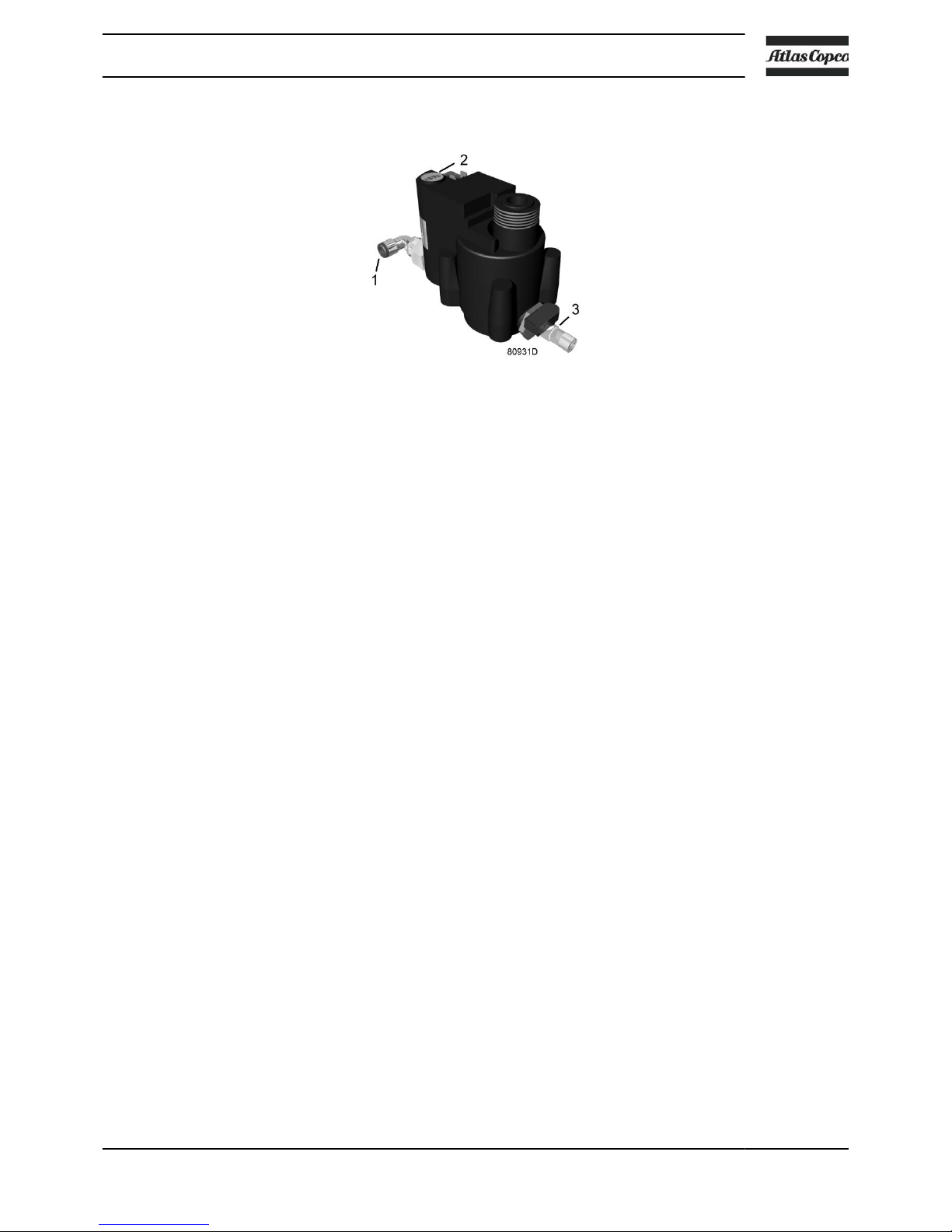
Automatic drain
The dryers are equipped with an electronic condensate drain (EWD). The condensate from the
condensate trap accumulates in a collector. When the condensate reaches a certain level, it is
discharged through the drain outlet (1).
The condensate can also be drained by pressing the test button (2).
The drain filter can be cleaned by opening the manual drain valve (3), see section Preventive
maintenance schedule.
Instruction book
2920 7140 52 23
3 Controller
3.1
General
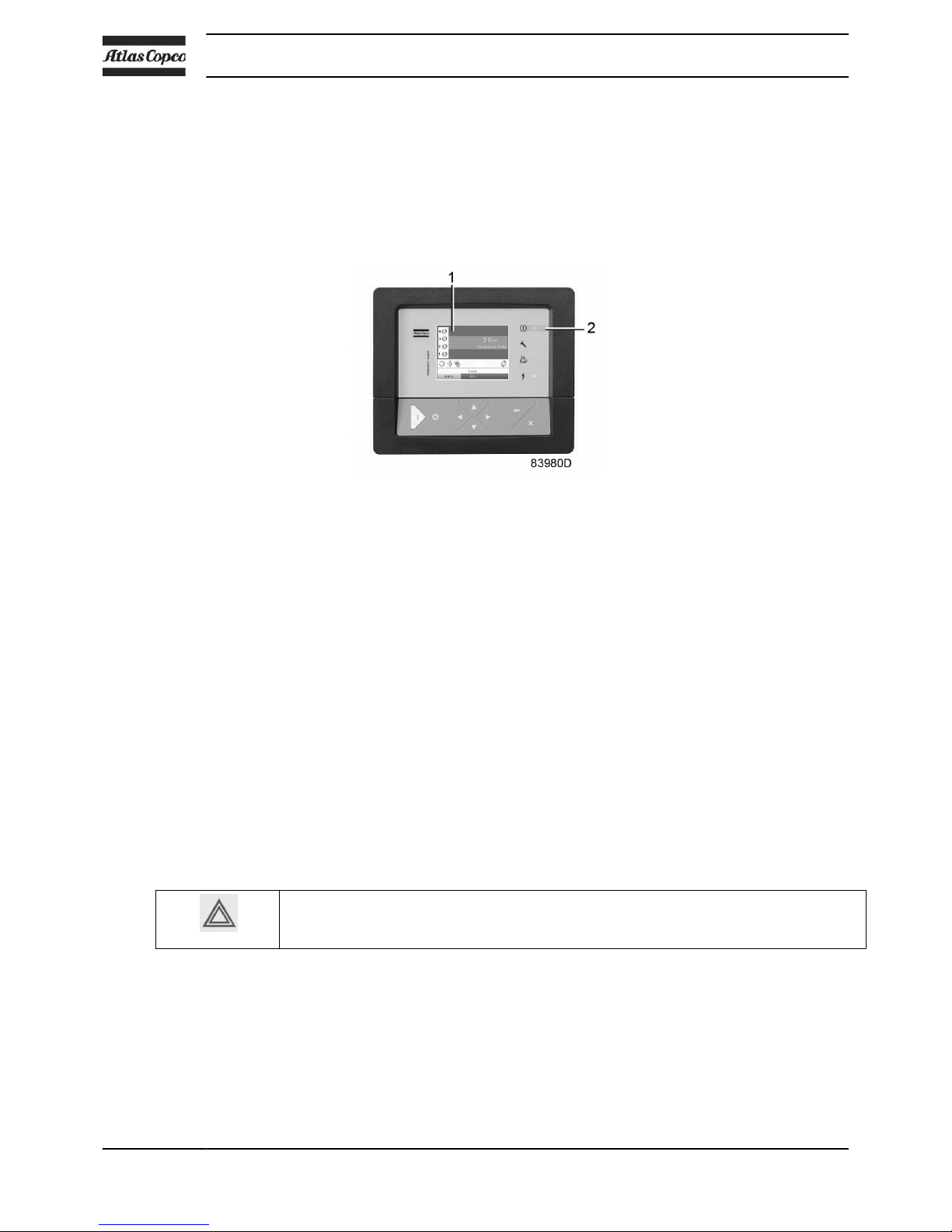
Control panel
Elektronikon® Graphic controller
Introduction
The controller has following functions:
•
Controlling the compressor
• Protecting the compressor
• Monitoring components subject to service
• Automatic restart after voltage failure (made inactive)
Automatic control of the compressor operation
The controller maintains the net pressure between programmable limits by automatically starting
and stopping one or more compressor modules. A number of programmable settings, e.g. the
starting and stopping pressures and the maximum allowed motor starting frequency and several
other parameters are hereby taken into account.
The controller stops the compressor whenever possible to reduce the power consumption and
restarts it automatically when the net pressure decreases.
A number of time based automatic start/stop commands can be programmed. Take into
account that a start command will be executed (if programmed and activated), even after
manually stopping the compressor.
Protecting the compressor
Shutdown
Several sensors are provided on the compressor. If one of the measured signals exceeds the
programmed shutdown level, the compressor will be stopped. This will be indicated on display (1)
and general alarm LED (2) will blink.
Instruction book
24 2920 7140 52
Remedy the trouble and reset the message. See also section Inputs menu.
Before remedying, consult the applicable safety precautions.
Shutdown warning / shutdown
If the compressor element temperature exceeds the factory set warning level, the compressor
element will be stopped for a short time and a warning will appear on the controller display (1)
and the general alarm LED (2) will light up.
In case of repetitive stops due to a too high temperature, a manual reset will be necessary before
restarting the compressor.
The compressor will also be stopped when the motor is overloaded.
A warning message will also appear if, on compressors with integrated dryer, the dew point
temperature is too high in relation to the ambient temperature.
Service warning
A number of service operations are grouped (called Service Plans). Each Service Plan has a
programmed time interval. If a time interval is exceeded, a message will appear on display (1) to
warn the operator to carry out the service actions belonging to that Service Plan.
The running hours will be recalculated with respect to the ambient temperature. This algorithm is
activated when the compressor is operated above 30 °C (86 °F) ambient.
Automatic restart after voltage failure
The controller has a built-in function to automatically restart the compressor when the voltage is
restored after voltage failure. For compressors leaving the factory, this function is made inactive.
If desired, the function can be activated.
Consult the Atlas Copco Customer Centre if a change is considered (password protected
function).
If the function is activated and provided the regulator was in the automatic operation
mode, the compressor will automatically restart if the supply voltage to the module is
restored within the programmed time interval.
Instruction book
2920 7140 52 25
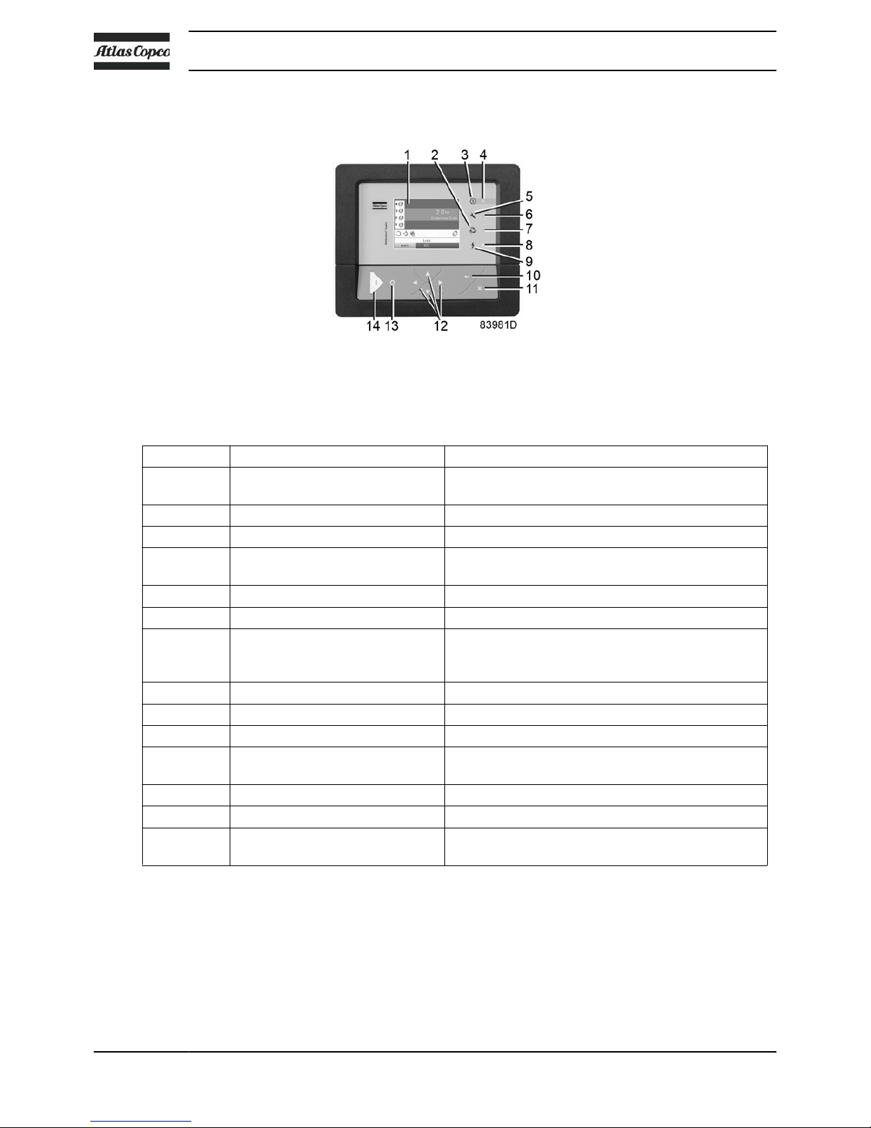
3.2 Control panel
Control panel
Parts and functions
Reference Designation Function
1 Display Shows the compressor operating condition and a
number of icons to navigate through the menu.
2 Pictograph Automatic operation
3 Pictograph General alarm
4 Alarm LED Flashes in case of a shutdown, is lit in case of a
warning condition.
5 Pictograph Service
6 Service LED Lights up if service is needed
7 Automatic operation LED Indicates that the regulator is automatically
controlling the compressor.
The compressor is stopped and restarted
8 Voltage on LED Indicates that the voltage is switched on.
9 Pictograph Voltage
10 Enter key Use this button to confirm the last action.
11 Escape key Use this button to go to previous screen or to end
the current action.
12 Scroll keys Keys to scroll through the menu.
13 Stop button Button to stop the compressor. LED (7) goes out.
14 Start button Button to start the compressor. LED (7) lights up
indicating that the controller is operative.
Instruction book
26 2920 7140 52
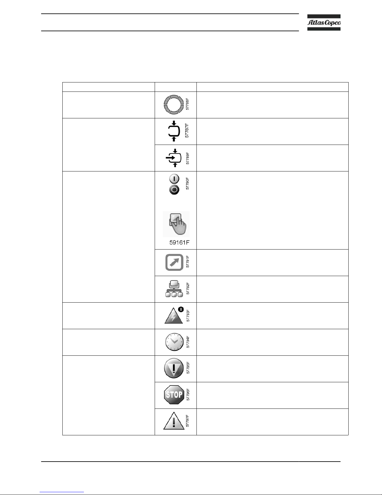
3.3 Icons used
Status icons
Name Icon Description
Stopped / Running When the compressor is stopped, the icon stands still.
When the compressor is running, the icon is rotating.
Compressor status Motor stopped
Motor running
Machine control mode
or
Local start / stop
Remote start / stop
Network control
Automatic restart after voltage
failure
Automatic restart after voltage failure is active
Week timer
Week timer is active
Active protection functions Emergency stop
Shutdown
Warning
Instruction book
2920 7140 52 27
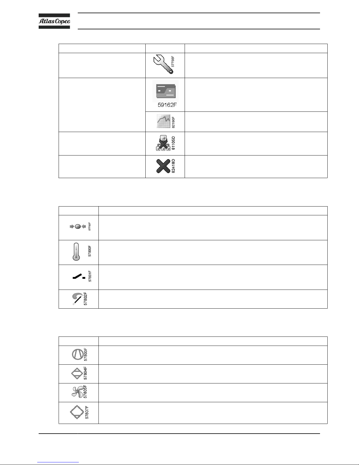
Name Icon Description
Service Service required
Main screen display Value lines display icon
Chart display icon
General icons No communication / network problem
Not valid
Input icons
Icon Description
Pressure
Temperature
Digital input
Special protection
System icons
Icon Description
Compressor element (LP, HP, ...)
Dryer
Fan
Drain
Instruction book
28 2920 7140 52
 Loading...