

Atlas Copco Secoroc GM RH Operator Instructions Manual

Secoroc Grinding Equipment
Secoroc GM RH
Operator's instructions and Spare parts list
Contents
Safety instructions
Safety instructions .............................................. 3
Technical data ...................................................... 4
General ................................................................4
Applications .........................................................4
Technical description ..........................................4
Controls and other parts ....................................5
General care instructions ...................................6
Grinding ............................................................... 7
Maintenance ........................................................ 8
Accessories and consumables ...........................9
Spare parts list ............................................................ 10
Grinding unit ..................................................... 11
Rotation head .................................................... 11
Guide unit .......................................................... 12
Arm unit ............................................................. 12
Bit holders ......................................................... 13
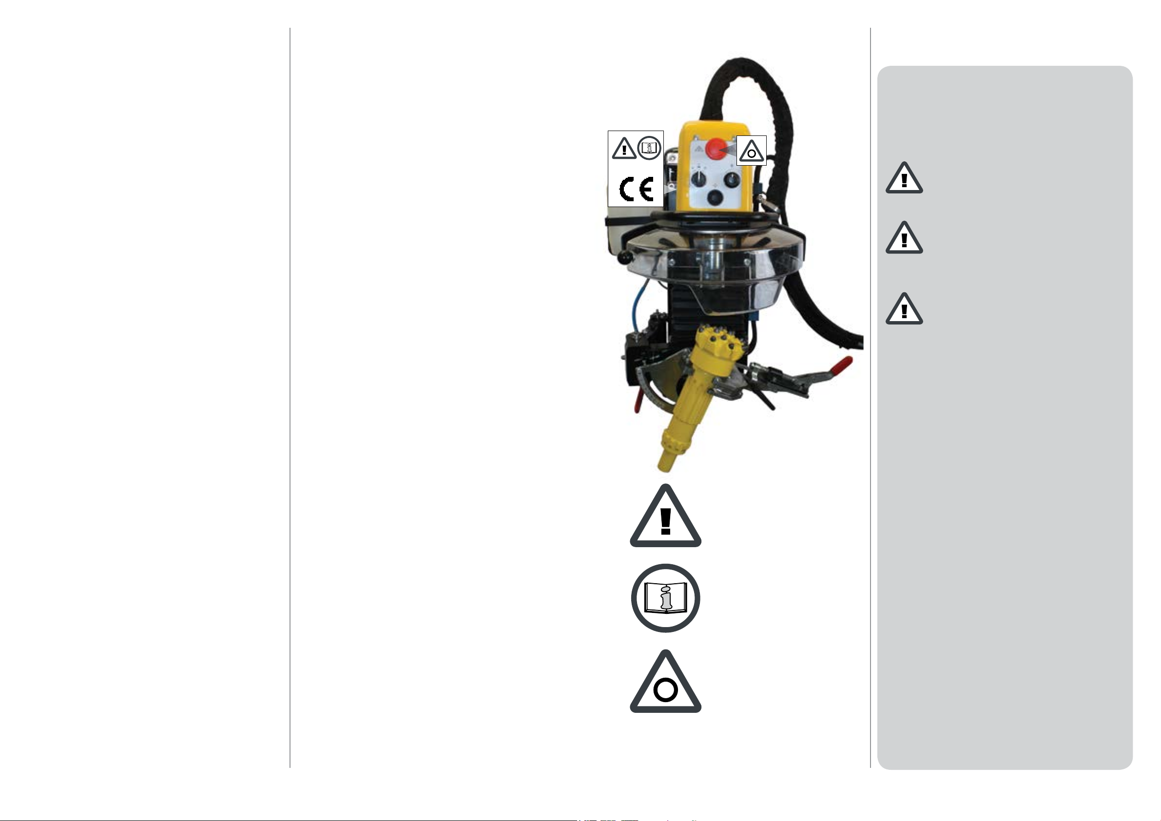
Before using the machine, read through these instruc-
tions carefully.
Important safety information is given at various points
in these instructions.
Special attention must be paid to the safety information
contained in frames and accompanied by a warning symbol
(triangle) and a “signal word“, as shown below:
DANGER
indicates an immediate risk that WILL result in serious
injury or death if the warning is not observed.
WARNING
indicates hazards or hazardous procedures which COULD
result in serious injury or death if the warning is not observed.
CAUTION
indicates hazards or hazardous procedures which COULD
result in injury or damage to equipment if the caution is not
observed.
Hydraulic unit .................................................... 14
Hydraulic diagram ............................................ 14
Electric unit ........................................................ 15
Wiring diagram ................................................. 15
Any unauthorized use or copying of all or part of the contents of
this publication is prohibited. This applies in particular to trademarks, model denominations, spare part numbers and drawings.
Subject to alteration without prior notice.
© Copyright 2000-2013
Atlas Copco Secoroc, Fagersta, Sweden
It can be dangerous to use the
machine if the care and maintenance instructions are not
followed carefully.
Before using the machine, read
the operator’s instructions carefully and then put them in a safe
place for future reference.
Emergency STOP
Always replace damaged or illegible signs
Use approved spare parts only. Any damage or malfunction that can be attributed to the use of unauthorized spare
parts is not covered by the machine warranty and invalidates product liability.
Also observe the following general safety instructions:
Make sure that there are no other personnel close to the
grinding machine while grinding is in progress.
Always wear goggles, protective clothing, steel toe safety
shoes, gloves and ear protectors during grinding. Any local
regulations must also be observed.
Wear an approved dust mask or arrange an effective
dust-extraction system. This is especially important when
grinding indoors.
The machine must not be used for any purpose other
than that for which it is intended. See “Applications“.
The machine must not be modied without the permission of the manufacturer. Modications not approved by
Atlas Copco Secoroc can incur the risk of serious injury to
yourself and others.
Before intervening in the oil or electrical systems, make
sure there is no pressure in the oil system and that the electrical system is shut down.
Beware of the risk of re and explosion that could be
initiated by sparks from the grinding work.
Before using the machine, visually check the hoses and
electric wiring for any damage. If any visible damage is
detected, replace before using machine.
Do not use the grinder when there is risk of:
seismic event, lightning or hydraulic hose burst.
32
Technical data
Specifications Tophammer Universal
Max. distance between bit
holder and grinding wheel
Drill bit diameter 35 - 127 mm 35 - 165 mm
Max. grip size n/a
Min. distance between
buttons
Rec. Oil pressure, min-max 150-210 bar 150-210 bar
Oil consumption 12 l/min 15 l/min
Cooling liquid consumption max 10 l/h max 10 l/h
Voltage +/- 24-28 VDC +/- 24-28 VDC
Current 6 A 6 A
Speed, spindle 9 500 rpm 12 000 rpm
Weight 81 kg 85 kg
Sound pressure during
grinding*
Sound power level during
grinding**
Vibration level during
grinding***
Manufactured: Atlas Copco Secoroc, Fagersta, Sweden
230 mm 230 mm
110 mm (QL6,
COP66)
3,5 mm 3,5 mm
85 dB (A) 85 dB (A)
95 dB (A 95 dB (A
< 2,5 m/s² < 2,5 m/s²
General
The Secoroc GM RH grinding machine is fully hydraulic powered and designed to be attached to a drill rig. It grinds cemented-carbide buttons and the surrounding body steel in the same
operation using a diamond-coated grinding wheel. The machine
has an automatic feeding device, which makes it simple to use.
Applications
The Secoroc GM RH is intended for grinding threaded and
tapered button bits up to 127 mm in diameter and DTH and COPROD bits up to 165 mm, and has a high grinding capacity.
Technical description
The Secoroc GM RH consists principally of the following component assemblies:
A rack with the guide and feed cylinder.
A grinding unit with the spindle and orbital rotation. The
control panel is mounted on the grinding unit.
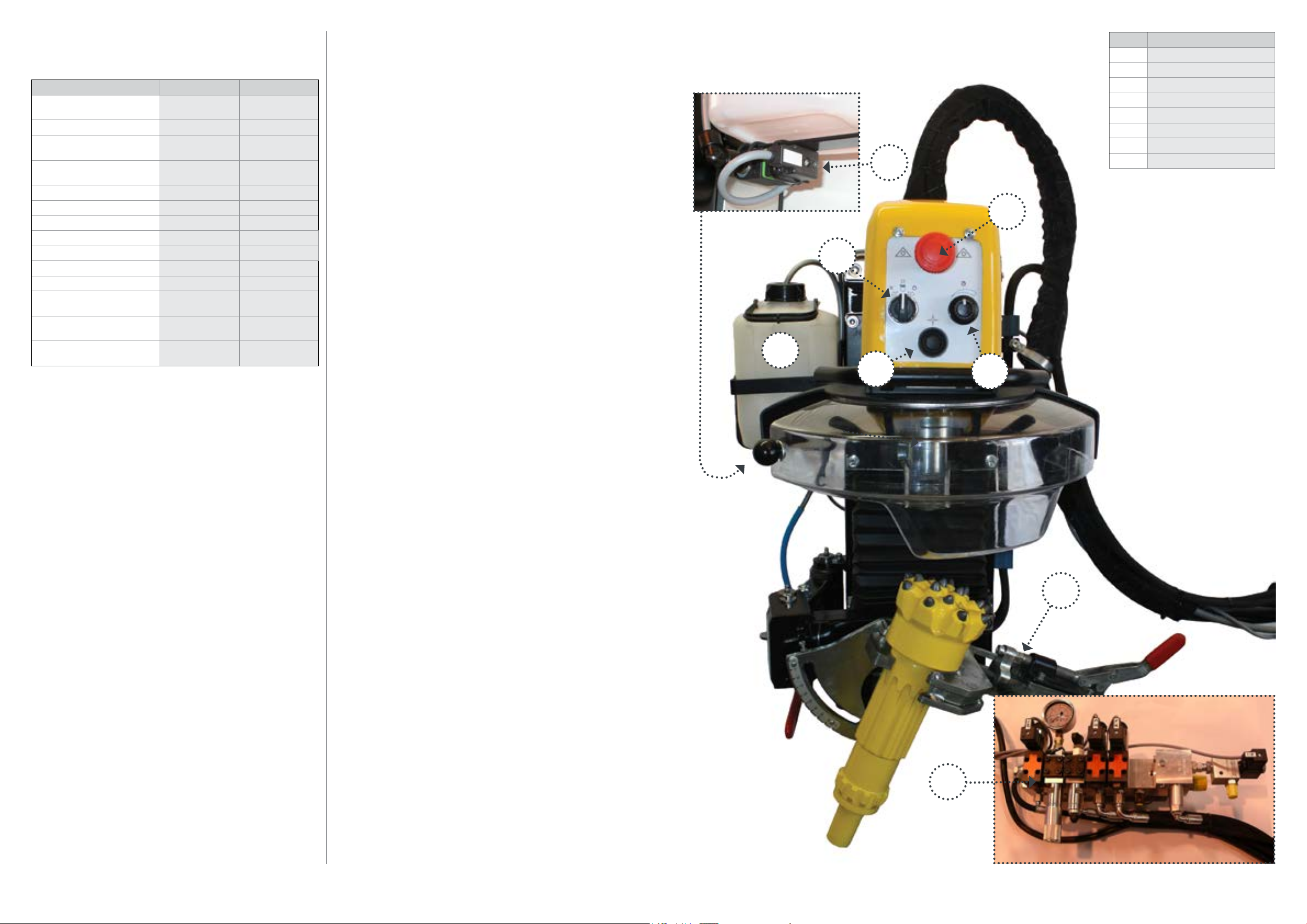
Controls and other parts
1
4
2
6
Ref.No. Description
1 Pump
2 Water tank
3 Emergency stop
4 Start/stop knob
5 Timer
6 Centring button
7 Bit holder
8 Hydraulic unit
3
5
* Equivalent continuous A-weighted sound pressure level measured at operator’s ear level during grinding. Possible spread due
to measuring method and production factors: 3 dB(A).
** Sound power level established in accordance with
EN 61029-1. Possible spread due to measuring method and
production factors: 3 dB(A). Average value for frequency range
100-6300 Hz.
*** Vibration measurement according to EN 61029-1.
Tophammer: A clamping device for threaded and tapered
bits (only for Tophammer bits).
Universal: A universal clamping device (for Tophammer-,
DTH- and COPROD bits).
A hydraulic valve unit.
A box with the electrical components.
A coolant pump with a coolant plastic can. Use water as cool-
ant medium. Add anti-freeze liquid (for example washer uid) to
prevent freezing.
A local emergency stop.
- The emergency stop function does not deactivate the drill rig,
only the grinding machine.
- When resetting the grinding machine emergency stop, the orbital movement will continue to it’s starting position.
7
8
54
 Loading...