

Atlas Copco QAS 275-325 Instruction Manual
Instruction Manual
for AC Generators
English
QAS 275-325 Volvo S2A APP

Printed matter N°
2954 3880 01
11/2010
QAS 275-325 Volvo
Instruction Manual for AC Generators
Instruction manual ..................................................................................5
Circuit diagrams .................................................................................... 91
ATLAS COPCO - PORTABLE AIR DIVISION
www.atlascopco.com

Warranty and Liability Limitation
Use only authorized parts.
Any damage or malfunction caused by the use of unauthorized parts is not covered by
Warranty or Product Liability.
The manufacturer does not accept any liability for any damage arising from modifications,
additions or conversions made without the manufacturer's approval in writing.
Neglecting maintenance or making changes to the setup of the machine can result in major
hazards, including fire risk.
While every effort has been made to ensure that the information in this manual is correct,
Atlas Copco does not assume responsibility for possible errors.
Copyright 2010, Atlas Copco Airpower n.v., Antwerp, Belgium.
Any unauthorized use or copying of the contents or any part thereof is prohibited.
This applies in particular to trademarks, model denominations, part numbers and drawings.
- 4 -

Congratulations on the purchase of your AC generator. It is a solid, safe and reliable machine, built according to the latest technology. Follow the instructions in this
booklet and we guarantee you years of troublefree operation. Please read the following instructions carefully before starting to use your machine.
While every effort has been made to ensure that the information in this manual is correct, Atlas Copco does not assume responsibility for possible errors. Atlas Copco
reserves the right to make changes without prior notice.
Contents
Safety precautions for portable
generators
......................................................6
Leading particulars .....................................13
General description ................................13
Bodywork ................................................15
Markings..................................................15
Drain plugs and filler caps.....................16
External fuel tank connection................16
Control and indicator panel Qc1002™..16
Control and indicator panel Qc2002™..26
Control and indicator panel Qc4002™..39
Output terminal board ...........................57
Dual frequency........................................58
Battery switch.........................................58
Spillage free frame.................................58
Operating instructions...............................59
Installation...............................................59
Connecting the generator......................60
Before starting........................................61
Operating Qc1002™ ...............................61
Operating Qc2002™ ...............................62
Operating Qc4002™ ...............................64
Maintenance ................................................65
Maintenance schedule ...........................65
Engine maintenance...............................67
(*) Measuring the alternator
insulation resistance...............................67
Engine fuel specifications......................67
Engine oil specifications ........................67
Engine oil level check.............................68
Engine oil and oil filter change..............68
Engine coolant specifications................69
Coolant check..........................................70
Storage of the generator...........................71
Storage....................................................71
Preparing for operation after storage ...71
Checks and trouble shooting....................72
Checking voltmeter P4 ...........................72
Checking ammeters P1, P2 and P3........72
Engine troubleshooting..........................72
Alternator troubleshooting ....................73
- 5 -
Options available for QAS 275-325
Volvo units
Circuit diagrams......................................74
Overview of the electrical options.........74
Description of the electrical options .....74
Overview of the mechanical options ....78
Desciption of the mechanical options...78
...................................................74
Technical specifications.............................79
Technical specifications for
QAS 275 units .........................................79
Technical specifications for
QAS 325 units .........................................84
Conversion list of SI units into
British units.............................................89
Dataplate .................................................89
Disposal.................................................... 90

Safety precautions for portable generators
To be read attentively and acted accordingly before towing, lifting, operating, performing maintenance or repairing the generator.
Introduction
The policy of Atlas Copco is to provide the users of their
equipment with safe, reliable and efficient products.
Factors taken into account are among others:
- the intended and predictable future use of the
products, and the environments in which they are
expected to operate,
- applicable rules, codes and regulations,
- the expected useful product life, assuming proper
service and maintenance,
- providing the manual with up-to-date information.
Before handling any product, take time to read the
relevant instruction manual. Besides giving detailed
operating instructions, it also gives specific information
about safety, preventive maintenance, etc.
Keep the manual always at the unit location, easy
accessible to the operating personnel.
See also the safety precautions of the engine and
possible other equipment, which are separately sent
along or are mentioned on the equipment or parts of the
unit.
These safety precautions are general and some
statements will therefore not always apply to a particular
unit.
Only people that have the right skills should be allowed
to operate, adjust, perform maintenance or repair on
Atlas Copco equipment. It is the responsibility of
management to appoint operators with the appropriate
training and skill for each category of job.
Skill level 1: Operator
An operator is trained in all aspects of operating the unit
with the push-buttons, and is trained to know the safety
aspects.
Skill level 2: Mechanical technician
A mechanical technician is trained to operate the unit the
same as the operator. In addition, the mechanical
technician is also trained to perform maintenance and
repair, as described in the instruction manual, and is
allowed to change settings of the control and safety
system. A mechanical technician does not work on live
electrical components.
Skill level 3: Electrical technician
An electrical technician is trained and has the same
qualifications as both the operator and the mechanical
technician. In addition, the electrical technician may
carry out electrical repairs within the various enclosures
of the unit. This includes work on live electrical
components.
Skill level 4: Specialist from the manufacturer
This is a skilled specialist sent by the manufacturer or its
agent to perform complex repairs or modifications to the
equipment.
In general it is recommended that not more than two
people operate the unit, more operators could lead to
unsafe operating conditions. Take necessary steps to
keep unauthorized persons away from the unit and
eliminate all possible sources of danger at the unit.
When handling, operating, overhauling and/or
performing maintenance or repair on Atlas Copco
equipment, the mechanics are expected to use safe
engineering practices and to observe all relevant local
safety requirements and ordinances. The following list is
a reminder of special safety directives and precautions
mainly applicable to Atlas Copco equipment.
Neglecting the safety precautions may endanger people
as well as environment and machinery:
- endanger people due to electrical, mechanical or
chemical influences,
- endanger the environment due to leakage of oil,
solvents or other substances,
- endanger the machinery due to function failures.
All responsibility for any damage or injury resulting
from neglecting these precautions or by non-observance
of ordinary caution and due care required in handling,
operating, maintenance or repair, also if not expressly
mentioned in this instruction manual, is disclaimed by
Atlas Copco.
- 6 -

The manufacturer does not accept any liability for any
damage arising from the use of non-original parts and for
modifications, additions or conversions made without
the manufacturer’s approval in writing.
If any statement in this manual does not comply with
local legislation, the stricter of the two shall be applied.
Statements in these safety precautions should not be
interpreted as suggestions, recommendations or
inducements that it should be used in violation of any
applicable laws or regulations.
General safety precautions
1 The owner is responsible for maintaining the unit in
a safe operating condition. Unit parts and
accessories must be replaced if missing or
unsuitable for safe operation.
2 The supervisor, or the responsible person, shall at
all times make sure that all instructions regarding
machinery and equipment operation and
maintenance are strictly followed and that the
machines with all accessories and safety devices, as
well as the consuming devices, are in good repair,
free of abnormal wear or abuse, and are not
tampered with.
3 Whenever there is an indication or any suspicion
that an internal part of a machine is overheated, the
machine shall be stopped but no inspection covers
shall be opened before sufficient cooling time has
elapsed; this to avoid the risk of spontaneous
ignition of oil vapour when air is admitted.
4 Normal ratings (pressures, temperatures, speeds,
etc.) shall be durably marked.
5 Operate the unit only for the intended purpose and
within its rated limits (pressure, temperature,
speeds, etc.).
6 The machinery and equipment shall be kept clean,
i.e. as free as possible from oil, dust or other
deposits.
7 To prevent an increase in working temperature,
inspect and clean heat transfer surfaces (cooler fins,
intercoolers, water jackets, etc.) regularly. See the
maintenance schedule.
8 All regulating and safety devices shall be
maintained with due care to ensure that they
function properly. They may not be put out of
action.
9 Pressure and temperature gauges shall be checked
regularly with regard to their accuracy. They shall
be replaced whenever outside acceptable tolerances.
10 Safety devices shall be tested as described in the
maintenance schedule of the instruction manual to
determine that they are in good operating condition.
11 Mind the markings and information labels on the
unit.
12 In the event the safety labels are damaged or
destroyed, they must be replaced to ensure operator
safety.
13 Keep the work area neat. Lack of order will increase
the risk of accidents.
14 When working on the unit, wear safety clothing.
Depending on the kind of activities these are: safety
glasses, ear protection, safety helmet (including
visor), safety gloves, protective clothing, safety
shoes. Do not wear the hair long and loose (protect
long hair with a hairnet), or wear loose clothing or
jewellery.
15 Take precautions against fire. Handle fuel, oil and
anti-freeze with care because they are inflammable
substances. Do not smoke or approach with naked
flame when handling such substances. Keep a fireextinguisher in the vicinity.
16a Portable generators (with earthing pin):
Earth the generator as well as the load properly.
16b Portable generators IT:
Note: This generator is built to supply a sheer
alternating current IT network.
Earth the load properly.
- 7 -

Safety during transport and installation
To lift a unit, all loose or pivoting parts, e.g. doors and
towbar, shall first be securely fastened.
Do not attach cables, chains or ropes directly to the
lifting eye; apply a crane hook or lifting shackle meeting
local safety regulations. Never allow sharp bends in
lifting cables, chains or ropes.
Helicopter lifting is not allowed.
It is strictly forbidden to dwell or stay in the risk zone
under a lifted load. Never lift the unit over people or
residential areas. Lifting acceleration and retardation
shall be kept within safe limits.
1 Before towing the unit:
- check the towbar, the brake system and the
towing eye. Also check the coupling of the
towing vehicle,
- check the towing and brake capability of the
towing vehicle,
- check that the towbar, jockey wheel or stand leg
is safely locked in the raised position,
- ascertain that the towing eye can swivel freely on
the hook,
- check that the wheels are secure and that the
tyres are in good condition and inflated correctly,
- connect the signalisation cable, check all lights
and connect the pneumatic brake couplers,
- attach the safety break-away cable or safety
chain to the towing vehicle,
- remove wheel chocks, if applied, and disengage
the parking brake.
2 To tow a unit use a towing vehicle of ample
capacity. Refer to the documentation of the towing
vehicle.
3 If the unit is to be backed up by the towing vehicle,
disengage the overrun brake mechanism (if it is not
an automatic mechanism).
4 Never exceed the maximum towing speed of the
unit (mind the local regulations).
5 Place the unit on level ground and apply the parking
brake before disconnecting the unit from the towing
vehicle. Unclip the safety break-away cable or
safety chain. If the unit has no parking brake or
jockey wheel, immobilize the unit by placing
chocks in front of and/or behind the wheels. When
the towbar can be positioned vertically, the locking
device must be applied and kept in good order.
6 To lift heavy parts, a hoist of ample capacity, tested
and approved according to local safety regulations,
shall be used.
7 Lifting hooks, eyes, shackles, etc., shall never be
bent and shall only have stress in line with their
design load axis. The capacity of a lifting device
diminishes when the lifting force is applied at an
angle to its load axis.
8 For maximum safety and efficiency of the lifting
apparatus all lifting members shall be applied as
near to perpendicular as possible. If required, a
lifting beam shall be applied between hoist and
load.
9 Never leave a load hanging on a hoist.
10 A hoist has to be installed in such a way that the
object will be lifted perpendicular. If that is not
possible, the necessary precautions must be taken to
prevent load-swinging, e.g. by using two hoists,
each at approximately the same angle not exceeding
30° from the vertical.
11 Locate the unit away from walls. Take all
precautions to ensure that hot air exhausted from the
engine and driven machine cooling systems cannot
be recirculated. If such hot air is taken in by the
engine or driven machine cooling fan, this may
cause overheating of the unit; if taken in for
combustion, the engine power will be reduced.
12 Generators shall be stalled on an even, solid floor,
in a clean location with sufficient ventilation. If the
floor is not level or can vary in inclination, consult
Atlas Copco.
13 The electrical connections shall correspond to local
codes. The machines shall be earthed and protected
against short circuits by fuses or circuit breakers.
14 Never connect the generator outlets to an
installation which is also connected to a public
mains.
15 Before connecting a load, switch off the
corresponding circuit breaker, and check whether
frequency, voltage, current and power factor
comply with the ratings of the generator.
16 Before transportation of the unit, switch off all the
circuit breakers.
- 8 -

Safety during use and operation
1 When the unit has to operate in a fire-hazardous
environment, each engine exhaust has to be
provided with a spark arrestor to trap incendiary
sparks.
2 The exhaust contains carbon monoxide which is a
lethal gas. When the unit is used in a confined
space, conduct the engine exhaust to the outside
atmosphere by a pipe of sufficient diameter; do this
in such a way that no extra back pressure is created
for the engine. If necessary, install an extractor.
Observe any existing local regulations.
Make sure that the unit has sufficient air intake for
operation. If necessary, install extra air intake ducts.
3 When operating in a dust-laden atmosphere, place
the unit so that dust is not carried towards it by the
wind. Operation in clean surroundings considerably
extends the intervals for cleaning the air intake
filters and the cores of the coolers.
4 Never remove a filler cap of the cooling water
system of a hot engine. Wait until the engine has
sufficiently cooled down.
5 Never refill fuel while the unit is running, unless
otherwise stated in the Atlas Copco Instruction
Book (AIB). Keep fuel away from hot parts such as
air outlet pipes or the engine exhaust. Do not smoke
when fuelling. When fuelling from an automatic
pump, an earthing cable should be connected to the
unit to discharge static electricity. Never spill nor
leave oil, fuel, coolant or cleansing agent in or
around the unit.
6 All doors shall be shut during operation so as not to
disturb the cooling air flow inside the bodywork
and/or render the silencing less effective. A door
should be kept open for a short period only e.g. for
inspection or adjustment.
7 Periodically carry out maintenance works according
to the maintenance schedule.
8 Stationary housing guards are provided on all
rotating or reciprocating parts not otherwise
protected and which may be hazardous to
personnel. Machinery shall never be put into
operation, when such guards have been removed,
before the guards are securely reinstalled.
9 Noise, even at reasonable levels, can cause irritation
and disturbance which, over a long period of time,
may cause severe injuries to the nervous system of
human beings.
When the sound pressure level, at any point where
personnel normally has to attend, is:
- below 70 dB(A): no action needs to be taken,
- above 70 dB(A): noise-protective devices should
be provided for people continuously being
present in the room,
- below 85 dB(A): no action needs to be taken for
occasional visitors staying a limited time only,
- above 85 dB(A): room to be classified as a noisehazardous area and an obvious warning shall be
placed permanently at each entrance to alert
people entering the room, for even relatively
short times, about the need to wear ear
protectors,
- above 95 dB(A): the warning(s) at the
entrance(s) shall be completed with the
recommendation that also occasional visitors
shall wear ear protectors,
- above 105 dB(A): special ear protectors that are
adequate for this noise level and the spectral
composition of the noise shall be provided and a
special warning to that effect shall be placed at
each entrance.
10 Insulation or safety guards of parts the temperature
of which can be in excess of 80°C (175°F) and
which may be accidentally touched by personnel
shall not be removed before the parts have cooled to
room temperature.
11 Never operate the unit in surroundings where there
is a possibility of taking in flammable or toxic
fumes.
12 If the working process produces fumes, dust or
vibration hazards, etc., take the necessary steps to
eliminate the risk of personnel injury.
13 When using compressed air or inert gas to clean
down equipment, do so with caution and use the
appropriate protection, at least safety glasses, for
the operator as well as for any bystander. Do not
apply compressed air or inert gas to your skin or
direct an air or gas stream at people. Never use it to
clean dirt from your clothes.
14 When washing parts in or with a cleaning solvent,
provide the required ventilation and use appropriate
protection such as a breathing filter, safety glasses,
rubber apron and gloves, etc.
- 9 -

15 Safety shoes should be compulsory in any
workshop and if there is a risk, however small, of
falling objects, wearing of a safety helmet should be
included.
16 If there is a risk of inhaling hazardous gases, fumes
or dust, the respiratory organs must be protected and
depending on the nature of the hazard, so must the
eyes and skin.
17 Remember that where there is visible dust, the finer,
invisible particles will almost certainly be present
too; but the fact that no dust can be seen is not a
reliable indication that dangerous, invisible dust is
not present in the air.
18 Never operate the generator in excess of its limits as
indicated in the technical specifications and avoid
long no-load sequences.
19 Never operate the generator in a humid atmosphere.
Excessive moisture causes worsening of the
generator insulation.
20 Do not open electrical cabinets, cubicles or other
equipment while voltage is supplied. If such cannot
be avoided, e.g. for measurements, tests or
adjustments, have the action carried out by a
qualified electrician only, with appropriate tools,
and ascertain that the required bodily protection
against electrical hazards is applied.
21 Never touch the power terminals during operation
of the machine.
22 Whenever an abnormal condition arises, e.g.
excessive vibration, noise, odour, etc., switch the
circuit breakers to OFF and stop the engine. Correct
the faulty condition before restarting.
23 Check the electric cables regularly. Damaged cables
and insufficient tightening of connections may
cause electric shocks. Whenever damaged wires or
dangerous conditions are observed, switch the
circuit breakers to OFF and stop the engine.
Replace the damaged wires or correct the dangerous
condition before restarting. Make sure that all
electric connections are securely tightened.
24 Avoid overloading the generator. The generator is
provided with circuit breakers for overload
protection. When a breaker has tripped, reduce the
concerned load before restarting.
25 If the generator is used as stand-by for the mains
supply, it must not be operated without control
system which automatically disconnects the
generator from the mains when the mains supply is
restored.
26 Never remove the cover of the output terminals
during operation. Before connecting or
disconnecting wires, switch off the load and the
circuit breakers, stop the machine and make sure
that the machine cannot be started inadvertently or
there is any residual voltage on the power circuit.
27 Running the generator at low load for long periods
will reduce the lifetime of the engine.
Safety during maintenance and repair
Maintenance, overhaul and repair work shall only be
carried out by adequately trained personnel; if required,
under supervision of someone qualified for the job.
1 Use only the correct tools for maintenance and
repair work, and only tools which are in good
condition.
2 Parts shall only be replaced by genuine Atlas Copco
replacement parts.
3 All maintenance work, other than routine attention,
shall only be undertaken when the unit is stopped.
Steps shall be taken to prevent inadvertent starting.
In addition, a warning sign bearing a legend such as
“work in progress; do not start” shall be attached to
the starting equipment.
On engine-driven units the battery shall be
disconnected and removed or the terminals covered
by insulating caps.
On electrically driven units the main switch shall be
locked in open position and the fuses shall be taken
out. A warning sign bearing a legend such as “work
in progress; do not supply voltage” shall be attached
to the fuse box or main switch.
4 Prior to stripping an engine or other machine or
undertaking major overhaul on it, prevent all
movable parts from rolling over or moving.
- 10 -

5 Make sure that no tools, loose parts or rags are left
in or on the machine. Never leave rags or loose
clothing near the engine air intake.
6 Never use flammable solvents for cleaning (fire-
risk).
7 Take safety precautions against toxic vapours of
cleaning liquids.
8 Never use machine parts as a climbing aid.
9 Observe scrupulous cleanliness during maintenance
and repair. Keep away dirt, cover the parts and
exposed openings with a clean cloth, paper or tape.
10 Never weld on or perform any operation involving
heat near the fuel or oil systems. Fuel and oil tanks
must be completely purged, e.g. by steam-cleaning,
before carrying out such operations. Never weld on,
or in any way modify, pressure vessels. Disconnect
the alternator cables during arc welding on the unit.
11 Support the towbar and the axle(s) securely if
working underneath the unit or when removing a
wheel. Do not rely on jacks.
12 Do not remove any of, or tamper with, the sound-
damping material. Keep the material free of dirt and
liquids such as fuel, oil and cleansing agents. If any
sound-damping material is damaged, replace it to
prevent the sound pressure level from increasing.
13 Use only lubricating oils and greases recommended
or approved by Atlas Copco or the machine
manufacturer. Ascertain that the selected lubricants
comply with all applicable safety regulations,
especially with regard to explosion or fire-risk and
the possibility of decomposition or generation of
hazardous gases. Never mix synthetic with mineral
oil.
14 Protect the engine, alternator, air intake filter,
electrical and regulating components, etc., to
prevent moisture ingress, e.g. when steam-cleaning.
15 When performing any operation involving heat,
flames or sparks on a machine, the surrounding
components shall first be screened with nonflammable material.
16 Never use a light source with open flame for
inspecting the interior of a machine.
17 When repair has been completed, the machine shall
be barred over at least one revolution for
reciprocating machines, several revolutions for
rotary ones to ensure that there is no mechanical
interference within the machine or driver. Check the
direction of rotation of electric motors when starting
up the machine initially and after any alteration to
the electrical connection(s) or switch gear, to check
that the oil pump and the fan function properly.
18 Maintenance and repair work should be recorded in
an operator’s logbook for all machinery. Frequency
and nature of repairs can reveal unsafe conditions.
19 When hot parts have to be handled, e.g. shrink
fitting, special heat-resistant gloves shall be used
and, if required, other body protection shall be
applied.
20 When using cartridge type breathing filter
equipment, ascertain that the correct type of
cartridge is used and that its useful service life is not
surpassed.
21 Make sure that oil, solvents and other substances
likely to pollute the environment are properly
disposed of.
22 Before clearing the generator for use after
maintenance or overhaul, submit it to a testrun,
check that the AC power performance is correct and
that the control and shutdown devices function
correctly.
- 11 -

Tool applications safety
Apply the proper tool for each job. With the knowledge
of correct tool use and knowing the limitations of tools,
along with some common sense, many accidents can be
prevented.
Special service tools are available for specific jobs and
should be used when recommended. The use of these
tools will save time and prevent damage to parts.
Battery safety precautions
Batteries
When servicing batteries, always wear protecting
clothing and glasses.
1 The electrolyte in batteries is a sulphuric acid
solution which is fatal if it hits your eyes, and which
can cause burns if it contacts your skin. Therefore,
be careful when handling batteries, e.g. when
checking the charge condition.
2 Install a sign prohibiting fire, open flame and
smoking at the post where batteries are being
charged.
3 When batteries are being charged, an explosive gas
mixture forms in the cells and might escape through
the vent holes in the plugs.
Thus an explosive atmosphere may form around the
battery if ventilation is poor, and can remain in and
around the battery for several hours after it has been
charged. Therefore:
- never smoke near batteries being, or having
recently been, charged,
- never break live circuits at battery terminals,
because a spark usually occurs.
4 When connecting an auxiliary battery (AB) in
parallel to the unit battery (CB) with booster cables:
connect the + pole of AB to the + pole of CB, then
connect the - pole of CB to the mass of the unit.
Disconnect in the reverse order.
- 12 -
Leading particulars
General description
The QAS 275-325 Volvo is an AC generator, built for continuous running at sites where no electricity is available or as stand-by in cases of interruption of the mains. The
generator operates at 50 Hz, 400 V - 3 phase, 50 Hz, 230 V - 3 phase and 60 Hz, 480 V - 3 phase. The QAS 275-325 Volvo generator is driven by a water-cooled diesel
engine, manufactured by VOLVO PENTA.
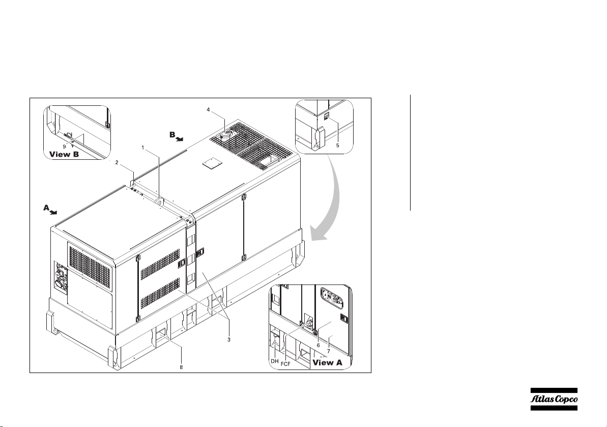
An overview of the main parts is given in the diagram below.
1 Lifting beam
2 Guiding rod
3 Side doors
4 Engine exhaust
5 Data plate
6 Door, access to control and indicator panel
7 Output terminal board
8 Hole for forklift
9 Earthing rod
DH Drain and access hole (in the frame)
FCF Filler cap fuel
- 13 -

A Alternator
AF Air filter
C Coupling
DFO Drain flexible engine oil
DFW Drain flexible cooling water
E Engine
FFan
FCO Filler cap engine oil
FCW Filler cap cooling water
FF Fuel filter
G1 Battery
ODP Oil drain pump
OF Oil filter
OLD Engine oil level dipstick
S1 Battery switch
- 14 -
Bodywork
The alternator, the engine, the cooling system, etc. are
enclosed in a sound-insulated bodywork that can be
opened by means of side doors (and service plates).
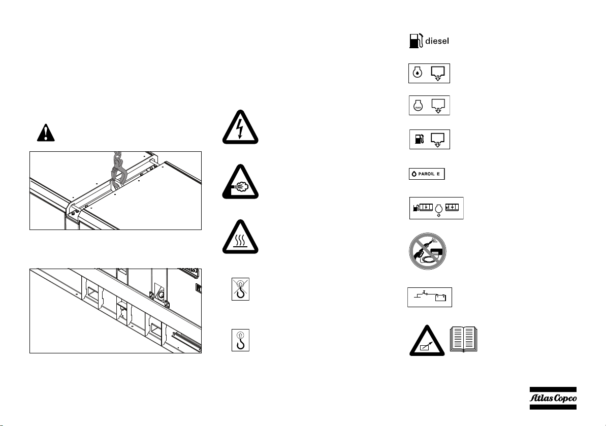
The lifting beam, to lift the generator by means of a
crane, is integrated in the bodywork and easily
accessible from the outside. The recesses in the roof
have guiding rods at both sides.
Never use the guiding rods to lift the
generator.
To be able to lift the generator by means of a forklift,
rectangular holes are provided at the bottom of the
frame.
The earthing rod, connected to the generator’s earth
terminal is located at the bottom of the frame on the
outside.
Markings
A brief description of all markings provided on the
generator is given hereafter.
Indicates that an electric voltage,
dangerous to life, is present. Never
touch the electric terminals during
operation.
Indicates that the engine exhaust is a
hot and harmful gas, which is toxic in
case of inhalation. Always make sure
that the unit is operated outside or in a
well-ventilated room.
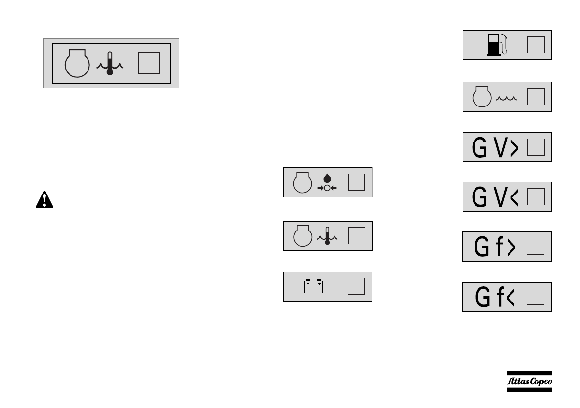
Indicates that these parts can become
very hot during operation (e.g. engine,
cooler, etc.). Always make sure that
these parts are cooled down before
touching them.
Indicates that the guiding rods may not
be used to lift the generator. Always
use the lifting rod in the roof of the
generator to lift it.
Indicates that the generator may be
refuelled with diesel fuel only.
Indicates the drain for the engine oil.
Indicates the drain for the coolant.
Indicates the drain plug for the engine
fuel.
Use PAROIL E only.
Indicates the external fueltank.
Indicates that the alternator should not
be cleaned with high pressurised
water.
Indicates the battery switch.
Indicates a lifting point of the
generator.
- 15 -
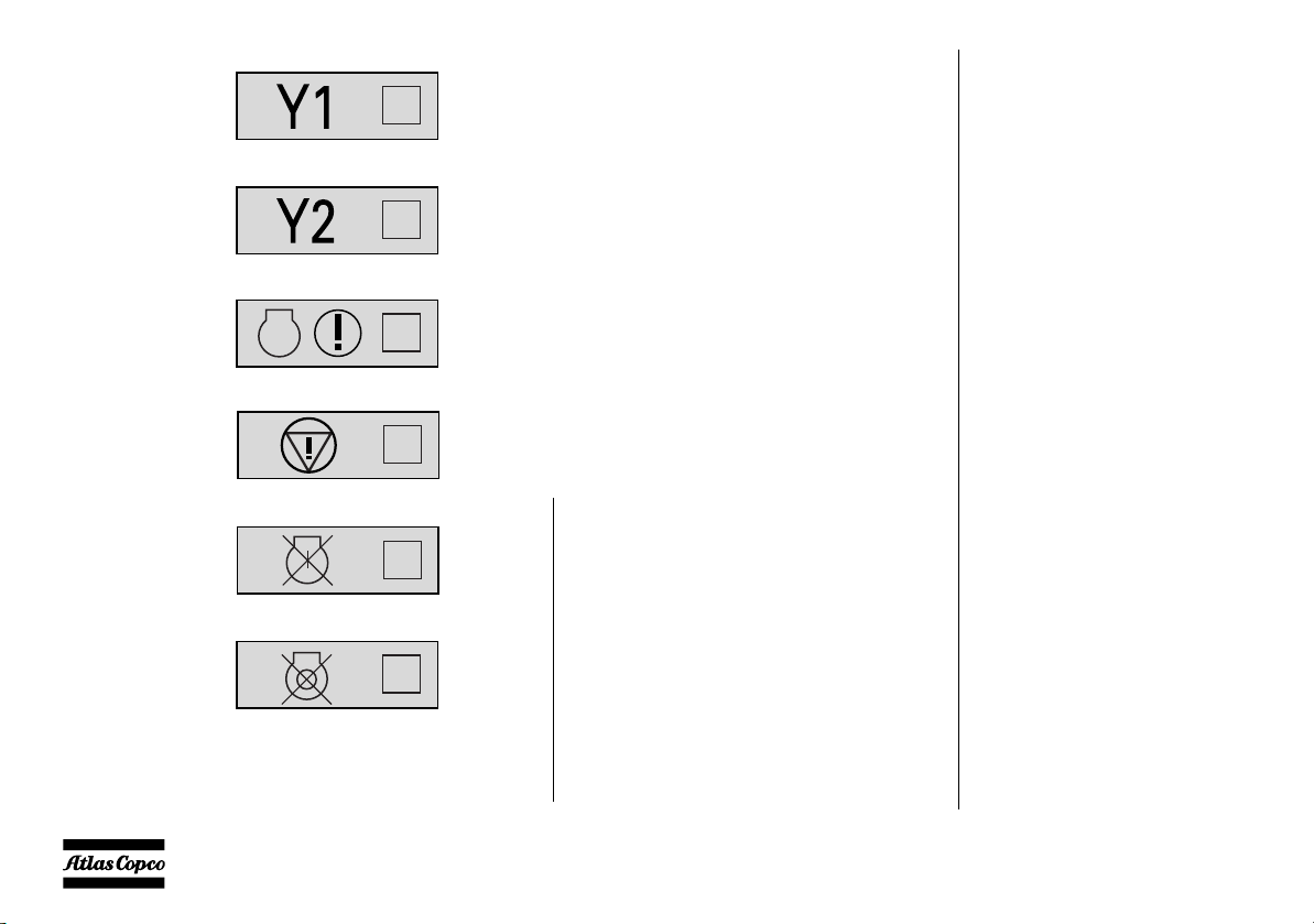
Indicates that the unit may
start automatically and that
the instruction book has to
be consulted prior to use.
Indicates the 3-way valve.
XXXXXXXXXXXXXXX
Engine oil
PAROIL E PAROIL Extra
Engine coolant PARCOOL EG
XXXXXXXXXXXX
XXXX XXXX XX
XXXXXXXXX
XXXX XXXX XX
XXXXXXXXX
XXXX XXXX XX
XX XXXXXXX
XXXX XXXX XX
XXXX XXXX XX
XX XXXXXXX
XXXX XXXX XX
XXXX XXXX XX
XX XXXXXXX
XXXX XXXX XX
XX XXXXXXX
XXXX XXXX XX
XX
XXXXXXX
XXXX XXXX XX
XX XXXXXXX
XXXX XXXX XX
XX XXXXXXX
XXXX XXXX XX
Indicates the partnumbe rs of
the different service packs
and of the engine oil. These
parts can be ordered to the
factory.
Drain plugs and filler caps
The drain holes for the engine oil, the coolant and the
plug for the fuel, are located and labelled on the
frame, the fuel drain plug at the front, the others at the
service side.
The drain flexibles for the engine oil and the engine
coolant can be brought to the outside of the generator
through the drain hole.
The drain hole can also be used to
guide external fueltank connections.
When connecting an external
fueltank, use the 3-way valves.
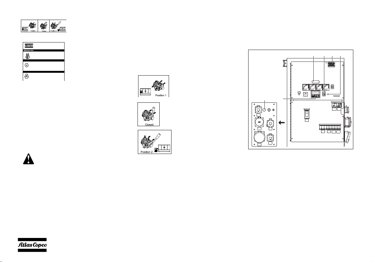
External fuel tank connection
The external fuel tank connection allows to bypass
the internal fuel tank and to connect an external fuel
tank to the unit.
Make sure to connect the fuel supply line as well as
the fuel return line. Connections to fuellines ought to
be air-tight to prevent air from entering the fuel
system.
Position 1: Indicates that the
fuel supply line to the engine is
connected to the internal
fueltank.
Position closed: Indicates that
the fuel supply line to the engine
is closed.
Position 2: Indicates that the
fuel supply line to the engine is
connected to the external
fueltank.
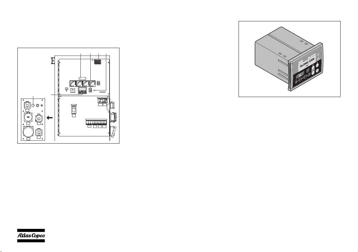
Control and indicator panel Qc1002™
General description Qc1002™ control panel
H0 S20A1X25 F10
OFF
L1L2
L1-N
L2L3 L2-N
L3-N
L3L1
S2
X2
X4
X5
X6
X3
A1 .......Qc1002™ display
F10 ......Fuse
The fuse activates when the current from the
battery to the engine control circuit exceeds
its setting. The fuse can be reset by pushing
the button.
LL LN
Q2
N13
Q1
Q3
Q4
Q6
Q5
H0 .......Panel light
- 16 -
S2 .......Emergency stop button
Qc1002 CAN
145
Push the button to stop the generator in case
of an emergency. When the button is
pressed, it must be unlocked, before the
generator can be restarted. The emergency
stop button can be secured in the locked
position with the key, to avoid unauthorized
use.
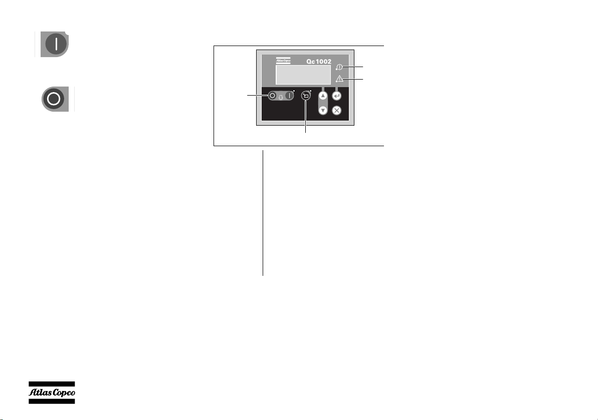
S20 ..... ON/OFF switch
Position O: No voltage is applied to the
Qc1002™ module, the generator will not
start.
Position I: Voltage is applied to the
Qc1002™ module, it is possible to start up
the generator.
X25 .....Terminal strip
Qc1002™ Module
The Qc1002™ module is located inside the control
panel. This control module will carry out all
necessary tasks to control and protect a generator,
regardless of the use of the generator.
This means that the Qc1002™ module can be used for
several applications.
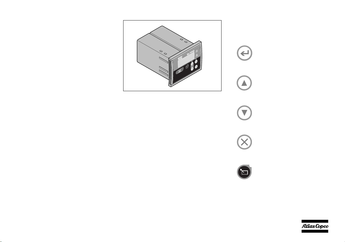
Pushbutton and LED functions
Following pushbuttons are used on
the Qc1002™
ENTER: Is used to select and
confirm changed settings in the
Parameter list.
UP: Is used to scroll through the
display information and to adjust
parameter value upwards.
DOWN: Is used to scroll through the
display information and to adjust
parameter value downwards.
BACK: Is used to leave the Alarm
pop-up window, to leave the
Parameter list and to leave menu's
without change.
REMOTE MODE: Is used to
activate the remote mode. The LED
indicates if the gen-set is put in
Remote Mode.
- 17 -
START: Is used to start the unit in
Remote
Power
Alarm
Start/Stop
Qc1002 CAN
145
Manual Mode.
STOP: Is used to stop the unit in
Manual or Remote Mode (always
with shutdown!). When the unit is
stopped with the STOP button in
Remote mode, it will automatically
go to Manual Mode.
Following LEDs are used on the
Qc1002™
Power Green LED indicates that the unit is
powered up.
Remote Green LED indicates that the Remote
Mode is selected.
Start/Stop Green LED indicates that the engine
is running.
Alarm Flashing red LED indicates that an
alarm is present. A continuous red
LED indicates that the alarm has been
acknowledged by the user. The exact
alarm is shown on the display.
Qc1002™ Menu Overview
At Qc1002™, the LCD will show following
information:
–in Normal condition (scroll through the
information using UP and DOWN):
• Status (eg: preheat, crank, run, cooldown,
extended stop time, …)
• Controller type & version
• Parameter list
•Alarm list
• LOG list
• Service Timer 1 & Service Timer 2
• Battery Voltage
• Coolant temperature
• Oil pressure
•RPM (speed)
• Fuel level
• Voltage - frequency - running hours
–in Alarm condition (scroll through the
information using UP and DOWN):
• a list of all active Alarms
It's possible to scroll through the views, using the UP
and DOWN buttons. The scrolling is continuous.
If a Special status comes up, the Status Display is
shown.
If an Alarm comes up, the Alarm Display is shown.
- 18 -

Controller type and version display
Qc1002 CAN
v1.00.0
Parameter
Alarm List
0 Alarm(s)
LOG List
Service 1
Service 2
59h
59h
25.2 VBattery
00168.1h
Alarm list display
Service timer 1 & Service timer 2
display
This view shows the controller type and the ASW
version number.
Parameter display
This view shows a number of Parameter settings and
gives access to them.
An overview is given in “Parameter list” on page 21.
This view shows the number of active alarms and
gives access to them.
An overview is given in “Alarm Display (pop-up
window)” on page 23.
LOG list display
This view shows the alarm memory and gives access
to it.
An overview is given in “LOG list” on page 25.
This view shows both Service timers. The service
timer indication is shown when service time has run
out. It can be removed by resetting the timers or
acknowledging the Service timer indication.
The service timer indications count upwards and give
an alarm when the set value is reached.
Resetting the Service Timers can be done through the
Parameter display.
Battery Voltage display
This view shows the Battery voltage and the running
hours.
- 19 -

Coolant temperature display
62˚CWater
00168.1h
3.2barOil
00168.1h
75%Fuel
00168.1h
50Hz400V
00168.1h
1500RPM
00168.1h
Fuel level display
Qc1002™ Menu Description
Status Display (pop-up window)
This view shows the Coolant temperature and the
running hours.
See also “Parameter list” on page 21 for selection
between °C and °F.
Oil pressure display
This view shows the Oil pressure and the running
hours.
See also “Parameter list” on page 21 for selection
between bar and psi.
This view shows the Fuel level and the running hours.
Voltage - frequency - running hours
display
This view shows the voltage, frequency and running
hours.
Engine speed display
This view shows the engine speed and running hours.
In case special statuses are entered, a pop-up window
will automatically be entered for as long as the status
is active.
The background screen is not updated when the status
pop-up window is active.
These special statuses are:
PREHEAT
START OFF/
EXTENDED
STOP TIMER
COOLDOWN
- 20 -

DIAGNOSTIC
If a special status has elapsed, the active view will be
entered again automatically.
If an Alarm comes up, the Alarm Display is shown.
Parameter list
The Parameter Menu's are pre-programmed!
A password will be asked for when an attempt to
change a setting is about to be done (user password =
2003).
Menu's shown on the Parameter list LCD:
– Running hours adjust
This menu is used to adjust the amount of running
hours. The running hours can only be highered,
not lowered.
– Unit Type
Unit type 2 for QAS 275-325 Volvo!
– Service Timer 2 reset
– Service Timer 1 reset
These menus are used to reset the service timers.
When a service timer alarm occurs and is
acknowledged, the service timer will be reset
automatically.
– Diagnostic Menu
This menu is used to power up the engine
electronics without starting the engine. When this
setting is switched on, electric power will be
supplied to the engine electronics after half a
minute delay. The unit can not be started as long
as this parameter is switched on.
– Unit Menu
This menu is used to select whether tempreature
and pressure should appear in °C/bar or °F/psi.
– Language selection
Icons is the default factory set language, but 6
other languages can be selected: English, French,
German, Italian, Spanish and Cyrillic (Russian).
All information in the Parameter List display is
always in English.
– Generator Underfrequency: failclass, enable,
delay, setpoint
– Generator Overfrequency: failclass, enable, delay,
setpoint
– Generator Undervoltage: failclass, enable, delay,
setpoint
– Generator Overvoltage: failclass, enable, delay,
setpoint
– Engine CAN communication
This menu is used to select the type of engine
electronics, the Qc1002™ controller should
communicate with via the Canbus.
It's possible to scroll between configuration menu's
by using the pushbuttons UP and DOWN.
Pushing the ENTER button activates the
configuration menu which is shown at the display.
- 21 -
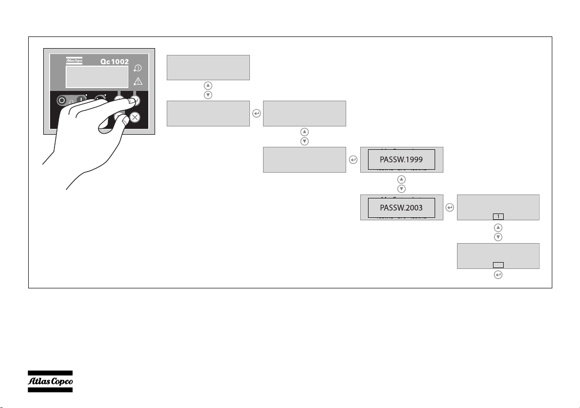
This is the described menu flow for changing the unit type:
Qc1002 CAN
145
Parameter Running time
Unit type
Unit type
Unit type
Qc1002 CAN
145
- 22 -
Alarm Display (pop-up window)
In case an Alarm occurs, a pop-up window will
automatically be displayed for as long as the alarm is
active, no matter which view is active. The flashing
red alarm LED will light up. The alarm icons will be
shown together with an acknowledgement check-box.
Push the ENTER button to acknowledge the alarm.
When the alarm has been acknowledged, a Vmarking will appear in the check-box and the red
alarm LED will light up continuously.
An alarm should always be
acknowledged before solving the
problem that causes the alarm.
The Alarm Display can always be left or entered
again by pushing the BACK button.
If more than one alarm comes up, it's possible to scroll
through the alarm messages with the UP and DOWN
pushbuttons. The newest alarm will be placed at the
bottom of the list (meaning that the older alarm stays
at the display when a newer alarm comes up).
If one or more than one alarm is present, an arrow at
the right of the display will be shown.
Following general groups of Alarms exist:
– Warning: Alarm LED lights up + Alarm pop-up
appears on the display + Alarm relay is
empowered (if configured)
– Trip of GB: ‘Warning’ actions + Generator
Contactor opens
– Trip and Stop: ‘Trip of GB’ actions + unit stops
after Cooldown
– Shutdown: ‘Trip of GB’ actions + unit stops
immediately
List of possible alarms:
LOW OIL
PRESSURE
HIGH COOLANT
TEMPERATURE
CHARGING
ALTERNATOR
LOW FUEL LEVEL
LOW COOLANT
LEVEL
GENERATOR
OVERVOLTAGE
GENERATOR
UNDERVOLTAGE
GENERATOR
OVERFREQUENCY
GENERATOR
UNDERFREQUENCY
- 23 -
SERVICE TIMER 1
SERVICE TIMER 2
ENGINE ALARM
EMERGENCY
STOP
START FAILURE
STOP FAILURE
Displaying the engine DM1 alarm
Besides some engine specific alarms shown in the
standard alarm list, also all Diagnostic messages
DM1 (active alarms) can be shown on the display.
Use the UP or DOWN buttons until DM1 is shown on
the display and press ENTER. The DM1 alarm log
will be shown on the display.
Use the UP and DOWN buttons to scroll through the
list.
The DM1 alarm log will always show the SPN code
(Diagnostics Codes) and the FMI code (Failure
Modes) of every engine failure.
For example, the error code for “Low Coolant Level
Shutdown” will be 111/01 (111 for “Coolant level”
and 01 for “Low level shutdown”).
The list below shows the most common error codes.
The DM1 alarm log for these codes will also show the
alarm text:
SPN16 "FUEL FILTER DIFF P"
pressure difference over fuel filter
SPN51 "THROTTLE POS"
throttle position
SPN52 "INTERCOOL TEMP"
intercooler temperature
SPN94 "FUEL PRESS"
fuel pressure
SPN95 "FUEL FILTER DIFF P"
pressure difference over fuel filter
SPN97 "WATER IN FUEL"
water in fuel
SPN98 "OIL LEVEL"
oil level
SPN99 "OIL FILTER DIFF P"
pressure difference over oil filter
SPN100 "OIL PRESSURE"
oil pressure
SPN101 "CRANKCASE PRESS"
crankcase pressure
SPN102 "TURBO BOOST PRESS"
turbo boost pressure
SPN104 "TURBO OIL PRESS"
turbo oil pressure
SPN105 "INTAKE MANIF TEMP"
intake manifold temperature
SPN106 "AIR INLET PRESSURE"
air inlet pressure
SPN110 "COOLANT TEMP"
coolant temperature
SPN111 "COOLANT LEVEL"
coolant level
SPN158 "BATT VOLTAGE"
battery voltage
SPN171 "AMBIENT AIR TEMP"
ambient air temperature
SPN172 "AIR IN TEMP"
air in temperature
SPN174 "FUEL TEMP"
fuel temperature
SPN175 "OIL TEMP"
oil temperature
- 24 -
SPN190 "SPEED"
Time: 00001h
EVENT LOG #04
Water
Qc1002
1
3
4
2
speed
FMI00 "HIGH LEVEL SHUTDOWN"
high level shutdown
FMI01 "LOW LEVEL SHUTDOWN"
low level shutdown
FMI15 "HIGH LEVEL WARNING"
high level warning
FMI16 "HIGH LEVEL ALARM"
high level alarm
FMI17 "LOW LEVEL WARNING"
low level warning
FMI18 "LOW LEVEL ALARM"
low level alarm
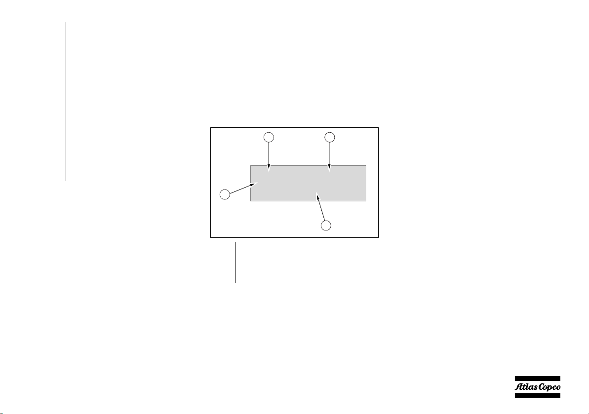
LOG list
The unit will keep an event log of the latest 30 events.
Events are:
– shutdowns
– service timer 1/2 reset
– unit type changes
Together with each event, the running hours at the
time of the event will be stored.
1 Controller type
2 Event number
3 Event
4 Running hours
Remote start operation
Installation wirings:
– X25.1 & X25.2 to be wired for the remote start
switch.
– X25.3 & X25.4 to be wired for the remote
contactor (open/close).
Fail classes
All the activated alarms of the Qc1002™ have their
own pre-defined fail class.
All alarms are enabled according to one of these three
statuses:
– disabled alarm, no supervision of alarm (OFF).
– enabled alarm, supervision of alarm all the time
(ON).
– running alarm, only supervision when the
machine is running (RUN).
- 25 -
Control and indicator panel Qc2002™
General description Qc2002™ control panel
H0 S20A1X25 F10
OFF
L1L2
L1-N
L2L3 L2-N
L3-N
L3L1
LL LN
S2
X2
X4
X5
X6
X3
A1 .......Qc2002™ display
F10...... Fuse
The fuse activates when the current from the
battery to the engine control circuit exceeds
its setting. The fuse can be reset by pushing
the button.
H0 .......Panel light
G
Q2
N13
Q1
Q3
Q4
Q6
Q5
S2 ....... Emergency stop button
Push the button to stop the generator in case
of an emergency. When the button is
pressed, it must be unlocked, before the
generator can be restarted. The emergency
stop button can be secured in the locked
position with the key, to avoid unauthorized
use.
S20 .....ON/OFF switch
Position O: No voltage is applied to the
Qc2002™ module, the generator will not
start.
Position I: Voltage is applied to the
Qc2002™ module, it is possible to start up
the generator.
X25 .....Terminal strip
Qc2002™ Module
The Qc2002™ module is located inside the control
panel. This control module will carry out all
necessary tasks to control and protect a generator,
regardless of the use of the generator.
This means that the Qc2002™ module can be used for
several applications.
- 26 -
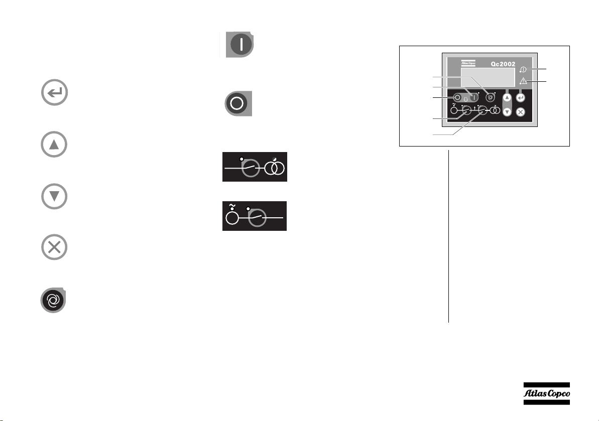
Pushbutton and LED functions
G
Qc2002 CAN
145
G
Power
Alarm
Start
Automatic
Generator
Contactor
Mains
Contactor
Stop
Following pushbuttons are used on
the Qc2002™
START: Is used to start the unit in
manual operation.
Following LEDs are used on the
Qc2002™
ENTER: Is used to select and
confirm changed settings in the
Parameter list.
UP: Is used to scroll through the
display information and to adjust
parameter value upwards.
DOWN: Is used to scroll through the
display information and to adjust
parameter value downwards.
BACK: Is used to leave the Alarm
pop-up window, to leave the
Parameter list and to leave menu's
without change.
AUTOMATIC: Is used to put the
unit in manual or automatic
operation.
STOP: Is used to stop the unit in
manual or automatic operation
(without cooldown). Wh en the unit is
stopped with the STOP button in
automatic operation, it will
automatically go to manual
operation.
MAINS CONTACTOR:
Is used to open or close the
Mains contactor, if the
Qc2002™ is in manual
operation.
GENERATOR
CONTACTOR: Is used to
open or close the Generator
contactor, if the Qc2002™
is in manual operation
- 27 -
Power Green LED indicates that the unit is
powered up.
Automatic Green LED indicates that the
Qc2002™ is in automatic operation.
Start/Stop Green LED indicates that the
Qc2002™ receives running
feedback (via the W/L input, via the
RPM value at the Canbus, or via the
AC frequency).
Generator
contactor
Green LED indicates that the
voltage and the frequency of the
alternator are within certain limits
for a certain time. It will be possible
to close the Generator Contactor
(both in Island and in AMF mode),
if the Mains contactor is open.

Mains
G L1-L2
G L2-L3
G L3-L1
400V
400V
400V
Qc2002 CAN
1.00.1
contactor
Alarm Flashing red LED indicates that an
Green LED indicates that it is
possible to close the Mains
Contactor (only in AMF mode), if
the Generator contactor is open.
alarm is present. A continuous red
LED indicates that the alarm has
been acknowledged by the use r. The
exact alarm is shown on the display.
Qc2002™ Menu Overview
At Qc2002™, the LCD will show following
information:
–in Normal condition (scroll through the
information using UP and DOWN):
• Status (eg: preheat, crank, cooldown, extended
stop time, …) (pop-up: this display is only
shown when a Special status comes up)
• Line voltages of the generator
• Controller type & version
• Parameter list
•Alarm list
• LOG list
• Service Timer 1 & Service Timer 2
• Battery Voltage
• RPM (speed)
• Coolant temperature
• Oil pressure
• Fuel level
• kWh counter
• Power factor, the frequency of the generator
and the frequency of the mains
• Line voltage, frequency and active power of
the generator
• Active, reactive and apparent power of the
generator
• Generator currents
• Phase voltages of the mains
• Line voltages of the mains
• Phase voltages of the generator
–in Alarm condition (scroll through the
information using UP and DOWN):
• a list of all active Alarms
It's possible to scroll through the views, using the UP
and DOWN buttons. The scrolling is continuous.
If a Special status comes up, the Status Display is
shown.
If an Alarm comes up, the Alarm Display is shown.
Line voltages generator display
This view shows the line voltages of the generator.
Controller type and version display
This view shows the controller type and the ASW
version number.
- 28 -

Parameter display
Parameter
Alarm List
0 Alarm(s)
LOG List
Service 1
Service 2
59h
59h
25.2 VBattery
00168.1h
0RPM
00168.1h
62˚CWater
00168.1h
LOG list display
Battery voltage display
This view shows a number of Parameter settings and
gives access to them.
An overview is given in “Parameter list” on page 31.
Alarm list display
This view shows the number of active alarms and
gives access to them.
An overview is given in “Alarm Display (pop-up
window)” on page 36.
This view shows the alarm memory and gives access
to it.
An overview is given in “LOG list” on page 39.
Service timer 1 & Service timer 2
display
This view shows both Service timers. The service
timer indication is shown when service time has run
out. It can be removed by resetting the timers or
acknowledging the Service timer indication.
The service timer indications count upwards and give
an alarm when the set value is reached.
Resetting the Service Timers can be done through the
Parameter display.
This view shows the Battery voltage and the running
hours.
RPM display
This view shows the engine speed and the running
hours.
Coolant temperature display
This view shows the Coolant temperature and the
running hours.
See also “Parameter list” on page 31 for selection
between °C and °F.
- 29 -

Oil pressure display
3.2barOil
00168.1h
75%Fuel
00168.1h
E
4860kWh
PF
GfL1
Mf L1
0.00
50Hz
50Hz
G L1-L2
G f L1
P
400V
50Hz
80kW
P
Q
S
80kW
0kVAr
80kVA
G I1
G I2
G I3
100A
100A
100A
kWh counter display
One line voltage - frequency - active
power display
This view shows the Oil pressure and the running
hours.
See also “Parameter list” on page 31 for selection
between bar and psi.
Fuel level display
This view shows the Fuel level and the running hours.
This view shows the kWh counter.
Power factor - frequency generator frequency mains display
This view shows the PF, the frequency of the
generator and the frequency of the mains (M f L1:
only in AMF mode).
This view shows one line voltage, frequency and
active power of the generator.
Active - reactive - apparent power
display
This view shows the active, reactive and apparent
power of the generator.
Generator current display
This view shows the generator current.
- 30 -
 Loading...