

Atlas Copco PowerMACS 4000 User Manual

User guide
PowerMACS 4000
Atlas Copco Tools and Assembly Systems
9836 3521 01
2010-11
Edition 10.3.0


Contents
Contents
1 Introduction ....................................................................................................................................... 15
1.1 Introduction - Overview ....................................................................................................................... 15
1.1.1 ToolsTalk PowerMACS, the friendly user interface ................................................................. 16
1.1.2 Intelligent tightening controllers, TCs ....................................................................................... 16
1.2 Tightening and Gauging ....................................................................................................................... 18
1.2.1 Gauging Functions .................................................................................................................... 18
1.2.2 Gauging Applications ................................................................................................................ 18
1.2.2.1 Torque To Turn Gauging Application ....................................................................... 19
1.2.2.2 Valve Lash Gauging Application ............................................................................... 20
1.3 Installing ToolsTalk PowerMACS ....................................................................................................... 21
2 System Architecture .......................................................................................................................... 23
2.1 System Architecture - Overview .......................................................................................................... 23
2.2 System Structure ................................................................................................................................... 24
2.3 Hardware Structure ............................................................................................................................... 26
2.3.1 Tightening Controller ................................................................................................................ 27
2.3.1.1 PTC Description......................................................................................................... 30
2.3.1.2 TC Description ........................................................................................................... 32
2.3.1.3 The TC HMI Menu System ....................................................................................... 34
2.3.2 Version conflict message........................................................................................................... 38
2.3.3 Console Computer (CC) ............................................................................................................ 38
2.3.4 Ethernet ..................................................................................................................................... 39
2.3.5 Peripheral Devices..................................................................................................................... 40
2.4 Automatic update of TC, Servo and Spindle ........................................................................................ 41
2.4.1 Automatic update Overview ...................................................................................................... 41
2.4.2 General function ........................................................................................................................ 41
2.4.3 Replacement of the System TC and Backup TC ....................................................................... 43
2.4.4 Replacement of TC3 – TCn....................................................................................................... 43
2.4.5 Updating a system with new software ....................................................................................... 43
2.4.6 Troubleshooting ........................................................................................................................ 43
2.4.7 Automatic Update of Servo software ........................................................................................ 44
2.4.8 Automatic Update of Spindle software ..................................................................................... 45
3 Basic Functions .................................................................................................................................. 47
3.1 Basic Functions - Overview ................................................................................................................. 47
3.2 Windows ............................................................................................................................................... 48
3.3 Help ...................................................................................................................................................... 51
3.4 The File menu ....................................................................................................................................... 52
3.5 How to Start up ..................................................................................................................................... 54
3.6 Viewing ................................................................................................................................................ 57
9836 3521 01 3

Contents
3.6.1 Assembly Overview .................................................................................................................. 57
3.6.1.1 Station Views ................................................................................................ ............. 60
3.6.2 System Map ............................................................................................................................... 61
3.6.3 View Cycle Data ....................................................................................................................... 64
3.6.4 View Statistics ................................................................................................ ........................... 66
3.6.5 View Trace ................................................................................................................................ 68
3.6.5.1 Select which trace to display ...................................................................................... 69
3.6.5.2 View of trace curves .................................................................................................. 72
3.6.5.3 Select Trace ................................................................................................................ 80
3.6.6 View Tightening Path ................................................................................................................ 81
3.6.7 View Event Log ........................................................................................................................ 82
3.6.8 View I/O signals ........................................................................................................................ 85
3.7 Reporter ................................................................................................................................................ 86
3.7.1 Predefined reporter settings ....................................................................................................... 86
3.7.2 New reporter .............................................................................................................................. 87
3.7.3 Remove reporter ........................................................................................................................ 90
3.7.4 Edit reporter .............................................................................................................................. 91
3.7.4.1 Adding Cycle Data Variables .................................................................................... 93
3.7.4.2 Layout of Cycle Data ................................................................................................. 95
3.7.4.3 Cycle Data layout example ........................................................................................ 98
3.7.4.4 Reporter Preview ..................................................................................................... 103
3.7.4.5 Advanced Event settings .......................................................................................... 104
3.7.4.6 Advanced CD settings .............................................................................................. 104
3.8 Security ............................................................................................................................................... 106
3.8.1 Registering groups................................................................................................................... 106
3.8.2 Registering users ..................................................................................................................... 107
3.8.3 Login and Logout .................................................................................................................... 108
3.9 Printing ............................................................................................................................................... 110
4 Set Up and Maintenance ................................................................................................................. 111
4.1 Set Up and Maintenance - Overview .................................................................................................. 111
4.2 Setups and How to handle them ......................................................................................................... 112
4.2.1 Backwards compatibility ......................................................................................................... 113
4.2.1.1 PLC conversion ........................................................................................................ 114
4.2.1.2 Compatibility between PM4000 Tightening and Gauging ................................ ....... 115
4.2.1.3 Upgrade of PLC environment .................................................................................. 115
4.3 Set up of a new system ....................................................................................................................... 116
4.3.1 Creating a new system using the Set Up Wizard ..................................................................... 116
4.4 System Map ................................................................................................................................ ........ 124
4.4.1 Logical view ............................................................................................................................ 125
4.4.1.1 System node ............................................................................................................. 126
4.4.1.2 Station node ............................................................................................................. 126
4 9836 3521 01

Contents
4.4.1.3 Bolt node .................................................................................................................. 128
4.4.1.4 Programs node ......................................................................................................... 128
4.4.1.5 Reporters node ......................................................................................................... 129
4.4.2 Hardware node ........................................................................................................................ 130
4.4.2.1 TC node .................................................................................................................... 131
4.4.2.2 Spindle node............................................................................................................. 133
4.4.2.3 Other device nodes ................................................................................................... 134
4.5 Station Set Up ..................................................................................................................................... 135
4.5.1 Advanced Station Settings....................................................................................................... 137
4.5.1.1 Work piece identifier ............................................................................................... 138
4.5.1.2 Multiple identifiers ................................................................................................ ... 138
4.5.1.3 PLC Event handling ................................................................................................ . 142
4.5.1.4 Conversion table ...................................................................................................... 142
4.6 Spindle Set Up .................................................................................................................................... 145
4.6.1 General page ............................................................................................................................ 145
4.6.2 Calibration page ...................................................................................................................... 146
4.6.3 Application page ..................................................................................................................... 147
4.6.3.1 Application External Equipment .............................................................................. 148
4.6.4 Angle Channels page ............................................................................................................... 149
4.6.4.1 Angle Double Transducer Check ............................................................................. 149
4.6.5 Torque Channels page ............................................................................................................. 151
4.6.5.1 Torque Double Transducer Check .......................................................................... 151
4.6.6 Diagnostic page ....................................................................................................................... 153
4.6.6.1 Static Zero Offset ..................................................................................................... 153
4.6.6.2 Dynamic Zero Offset and Angle Count ................................................................... 154
4.6.6.3 Flying Zero Offset ................................................................................................ .... 154
4.6.6.4 Order of execution ................................................................................................... 155
4.6.7 Motortune page ....................................................................................................................... 156
4.6.8 Automatic transducer protections ............................................................................................ 157
4.7 I/O ....................................................................................................................................................... 158
4.7.1 Local I/O ................................................................................................................................. 161
4.8 ID device Set Up ................................................................................................................................ 162
4.9 Assembly Overview Set Up ............................................................................................................... 163
4.10 PLC Parameters Set Up ...................................................................................................................... 167
4.11 SRAM ................................................................................................................................................. 168
4.12 Options ............................................................................................................................................... 169
4.12.1 Set Customer step names ......................................................................................................... 171
4.12.2 Set Customer error codes ........................................................................................................ 172
4.13 Setup Problems ................................................................................................................................... 174
4.14 Table Export and Import ..................................................................................................................... 175
4.15 Table Copy ......................................................................................................................................... 177
9836 3521 01 5

Contents
4.16 Handling of the setup in the target system .......................................................................................... 178
4.16.1 Backup of the setup ................................................................................................................. 178
4.16.2 Replacement of TCs ................................................................................................................ 180
4.17 Maintenance ....................................................................................................................................... 181
4.17.1 Select Target System ............................................................................................................... 184
4.17.2 Test Bolts ................................................................................................................................ 186
4.17.3 Calibration procedures in PowerMACS .................................................................................. 190
4.17.3.1 General ................................................................................................................... 190
4.17.3.2 Torque .................................................................................................................... 192
4.17.3.3 Angle ................................................................................................ ...................... 194
4.17.3.4 Wind Up Coefficient .............................................................................................. 195
4.17.3.5 Current (torque) ..................................................................................................... 197
4.17.4 Event Statistics ........................................................................................................................ 198
4.17.5 Service Log ............................................................................................................................. 199
4.17.6 Replace ID String .................................................................................................................... 200
4.17.7 Configure Target System......................................................................................................... 201
4.17.7.1 Advanced mode ..................................................................................................... 202
4.17.7.2 Restart of TC’s after download .............................................................................. 203
4.17.7.3 Information fields ................................ ................................................................ ... 203
4.17.7.4 Prepare TC for download of software .................................................................... 207
4.17.7.5 Change Net Data .................................................................................................... 209
4.17.8 Clear data ................................................................................................................................ 210
4.17.9 Compare programs .................................................................................................................. 211
4.17.10 Check for System Conflicts ................................................................................................ 213
4.17.11 TC Crash Log ..................................................................................................................... 214
5 PLC ................................................................................................................................................... 215
5.1 PLC - Overview .................................................................................................................................. 215
5.2 General ............................................................................................................................................... 216
5.3 System Globals ................................................................................................................................... 218
5.3.1 Station variables ...................................................................................................................... 218
5.3.1.1 Loosening cycles ...................................................................................................... 225
5.3.2 Bolt variables .......................................................................................................................... 231
5.3.3 ID device variables .................................................................................................................. 235
5.3.4 Multiple identifier variables .................................................................................................... 236
5.3.5 GM DeviceNet variables ......................................................................................................... 238
5.3.6 DC PLUS variables ................................................................................................................. 240
5.3.7 Globals .................................................................................................................................... 243
5.3.8 Bolt specific commands .......................................................................................................... 244
5.3.9 Device commands ................................................................................................................... 247
5.4 Programming the PLC ........................................................................................................................ 249
5.5 PLC Console ................................ ................................ ................................................................ ....... 254
6 9836 3521 01

Contents
5.6 PLC Parameters .................................................................................................................................. 256
5.7 Display PLC Status ............................................................................................................................. 257
6 Tightening......................................................................................................................................... 258
6.1 Tightening - Overview........................................................................................................................ 258
6.2 Create a new Tightening Program ...................................................................................................... 259
6.3 The Tightening Program form ............................................................................................................ 260
6.3.1 Tightening Program step operations ........................................................................................ 262
6.4 The Mode Table form ......................................................................................................................... 264
6.5 Tightening Program ............................................................................................................................ 266
6.5.1 Program Properties .................................................................................................................. 268
6.5.1.1 Program Common properties ................................................................................... 268
6.5.1.2 Program User variables ............................................................................................ 268
6.5.1.3 Program Settings ...................................................................................................... 270
6.5.2 Step – Control ......................................................................................................................... 273
6.5.2.1 DT - Run until Dyna-TorkTM ................................................................................... 274
6.5.2.2 DT2 - Run until Dyna-TorkTM, method 2................................................................. 276
6.5.2.3 DT3 - Run until Dyna-TorkTM, method 3................................................................. 277
6.5.2.4 T - Run until Torque ................................................................................................ 278
6.5.2.5 TC - Run until Torque with Current Control ........................................................... 279
6.5.2.6 AO - Run until Angle with overshoot compensation ............................................... 280
6.5.2.7 A - Run until Angle .................................................................................................. 282
6.5.2.8 Y1 - Run until Yield point, method 1 ...................................................................... 283
6.5.2.9 Y2 - Run until Yield point, method 2 ...................................................................... 284
6.5.2.10 LT - Loosen until torque ........................................................................................ 285
6.5.2.11 RA - Release angle ................................................................................................. 287
6.5.2.12 PA - Run until Projected angle ............................................................................... 289
6.5.2.13 TD - Run until Torque has decreased..................................................................... 290
6.5.2.14 TI - Run until Time ................................................................................................ 291
6.5.2.15 E1 - Run Engage method 1 .................................................................................... 291
6.5.2.16 E2 - Run Engage method 2 .................................................................................... 291
6.5.2.17 NS - Run until next step ......................................................................................... 291
6.5.2.18 GS - Run Gear Shift ............................................................................................... 292
6.5.2.19 PLC - Run PLC step............................................................................................... 292
6.5.2.20 JOG - Run until digital input goes high / low ........................................................ 293
6.5.2.21 W - Wait ................................................................................................................. 293
6.5.2.22 TA – Run Torque-Angle with no stop ................................................................... 294
6.5.2.23 SR – Socket Release .............................................................................................. 300
6.5.2.24 ADT-Angle Delta Torque ...................................................................................... 301
6.5.2.25 SG - Snug Gradient ................................................................................................ 303
6.5.2.26 D - Diagnostic Step ................................ ................................................................ 304
6.5.2.27 BCT – Backlash correction (only available for Gauging) ...................................... 305
9836 3521 01 7

Contents
6.5.2.28 POS - Run to Position (only available for Gauging) .............................................. 305
6.5.3 Step – Restriction .................................................................................................................... 307
6.5.3.1 Fail Safe Torque ....................................................................................................... 308
6.5.3.2 Fail Safe Time .......................................................................................................... 309
6.5.3.3 Fail Safe Angle ........................................................................................................ 310
6.5.3.4 Min Torque Restriction ............................................................................................ 311
6.5.3.5 Gradient ................................................................................................................... 313
6.5.3.6 Cross Thread and Gradient ...................................................................................... 315
6.5.3.7 Torque Profile .......................................................................................................... 316
6.5.3.8 Angle Difference ...................................................................................................... 318
6.5.3.9 Torque Difference .................................................................................................... 319
6.5.4 Step – Check ........................................................................................................................... 320
6.5.4.1 Result values from checks ........................................................................................ 321
6.5.4.2 Check peak torque ................................................................................................ .... 322
6.5.4.3 Check torque in angle window ................................................................................. 324
6.5.4.4 Check torque in time window .................................................................................. 325
6.5.4.5 Check mean torque .................................................................................................. 326
6.5.4.6 Check angle .............................................................................................................. 327
6.5.4.7 Check Post view Torque .......................................................................................... 329
6.5.4.8 Check T/T3 (Current as Torque) .............................................................................. 331
6.5.4.9 Check shut off torque ............................................................................................... 332
6.5.4.10 Check torque rate ................................................................................................... 333
6.5.4.11 Check Zero Crossing (only available for Gauging) .............................................. 336
6.5.4.12 Check time ............................................................................................................. 338
6.5.4.13 Check Yield Point Angle ....................................................................................... 338
6.5.4.14 Check Stick Slip ..................................................................................................... 340
6.5.4.15 Delta T (only available for Gauging) ..................................................................... 342
6.5.4.16 Low Spot Torque (only available for Gauging) ..................................................... 343
6.5.4.17 Check Position (only available for Gauging) ......................................................... 343
6.5.4.18 Check Backlash angle (only available for Gauging) .............................................. 344
6.5.4.19 Check external input (only available for Gauging) ................................................ 344
6.5.5 Step – Rejects .......................................................................................................................... 345
6.5.5.1 Checking the bolt status ........................................................................................... 346
6.5.5.2 Deciding what to do ................................................................................................. 347
6.5.5.3 Configuring Reject Management ............................................................................. 350
6.5.5.4 Advanced RM Actions ............................................................................................. 352
6.5.5.5 Cycle RM ................................................................................................................. 353
6.5.5.6 Reject management states ........................................................................................ 355
6.5.5.7 Reject management examples .................................................................................. 361
6.5.6 Step – Ramps & Other ............................................................................................................ 363
6.5.6.1 Ramps & Other – Ramps ......................................................................................... 364
8 9836 3521 01

Contents
6.5.6.2 Ramps & Other – Other ........................................................................................... 365
6.5.6.3 Ramps & Other – Store Position (only available for Gauging) ................................ 366
6.5.6.4 Ramps & Other – Signals at step start and end (only available for Gauging) .......... 367
6.5.7 Zones (only available for Gauging) ......................................................................................... 368
6.6 Bolt Monitoring .................................................................................................................................. 369
6.6.1 Monitoring Check – Final Peak Torque .................................................................................. 372
6.6.2 Monitoring Check – Angle ...................................................................................................... 373
6.6.3 Monitoring Check – Torque Rate ............................................................................................ 376
6.6.4 Monitoring Check – Monitoring Yield point torque and angle ............................................... 379
6.7 Result variables .................................................................................................................................. 382
6.7.1 Statuses .................................................................................................................................... 382
6.7.2 Station level result variables.................................................................................................... 383
6.7.3 Bolt level result variables ........................................................................................................ 385
6.7.3.1 Errors ....................................................................................................................... 390
6.7.3.2 Warnings .................................................................................................................. 394
6.7.4 Step level result variables ........................................................................................................ 395
6.8 Servo and spindle protections ............................................................................................................. 399
6.8.1 Stall protection ........................................................................................................................ 399
6.8.2 How to avoid the problems ..................................................................................................... 399
7 SPC and Statistics ............................................................................................................................ 401
7.1 SPC - Overview .................................................................................................................................. 401
7.2 SPC, Statistical Process Control ......................................................................................................... 402
7.2.1 Data Collection ........................................................................................................................ 402
7.2.2 Calculations for subgroups ...................................................................................................... 403
7.2.3 Calculations and checks .......................................................................................................... 403
7.2.4 SPC constants .......................................................................................................................... 407
7.3 SPC set up .......................................................................................................................................... 408
7.4 Shift Reports and Shift Set Up............................................................................................................ 410
7.4.1 Shift Set Up ............................................................................................................................. 411
8 Peripheral Devices ........................................................................................................................... 413
8.1 Peripheral Devices - Overview ........................................................................................................... 413
8.2 Add a device ................................................................ ................................................................ ....... 415
8.3 Status of a device ................................................................................................................................ 417
8.4 Standard Accessory Devices............................................................................................................... 418
8.4.1 Stacklight................................................................................................................................. 418
8.4.2 Indicator Box ........................................................................................................................... 419
8.4.3 Operator Panel ................................................................ ................................ ......................... 421
8.5 I/O Device .......................................................................................................................................... 423
8.6 Printer on TC ...................................................................................................................................... 424
8.7 Printer or File on CC .......................................................................................................................... 424
8.8 PLC ..................................................................................................................................................... 425
8.9 ID device ............................................................................................................................................ 429
9836 3521 01 9

Contents
8.10 ToolsNet ............................................................................................................................................. 436
8.11 Ethernet Protocols .............................................................................................................................. 439
8.12 Fieldbus Interface ............................................................................................................................... 480
8.9.1 Type specific parameters ......................................................................................................... 430
8.9.1.1 Barcode scanner ....................................................................................................... 430
8.9.1.2 Pepperl + Fuchs escort memory ............................................................................... 431
8.9.1.3 Allen Bradley escort memory .................................................................................. 432
8.9.1.4 Omron escort memory ............................................................................................. 433
8.9.1.5 Euchner card reader ................................................................................................. 435
8.11.1 Open Protocol .......................................................................................................................... 442
8.11.1.1 Automatic/manual mode ........................................................................................ 443
8.11.1.2 Supported message types ....................................................................................... 445
8.11.1.3 TC Status Record Formats ..................................................................................... 448
8.11.1.4 TC Result Record Formats ..................................................................................... 449
8.11.2 DaimlerChrysler PFCS ................................................................................................ ............ 451
8.11.2.1 Supported message types ....................................................................................... 452
8.11.2.2 PFD Result Record Formats................................................................................... 452
8.11.3 FSH ......................................................................................................................................... 453
8.11.3.1 Supported message types ....................................................................................... 454
8.11.3.2 TC Result Record Formats ..................................................................................... 455
8.11.4 DC PLUS ................................................................................................................................ 456
8.11.4.1 Parameters for PDT ................................................................................................ 457
8.11.4.2 Parameters for PQD ............................................................................................... 459
8.11.4.3 Handling of PN, KN and LI, in protocol version PDT ........................................... 461
8.11.4.4 Handling of QO and FP ......................................................................................... 462
8.11.4.5 SAW / WIS ............................................................................................................ 463
8.11.4.6 SPS ......................................................................................................................... 465
8.11.4.7 VBA ....................................................................................................................... 466
8.11.4.8 SSE......................................................................................................................... 467
8.11.4.9 TC Result Formats for PDT ................................................................................... 468
8.11.4.10 TC Result Format for PQD .................................................................................. 470
8.11.4.11 Selecting the data to report ................................................................................... 472
8.11.4.12 Selecting the data to report ................................................................................... 472
8.11.5 I-P.M. ...................................................................................................................................... 473
8.11.5.1 Mapping of data ..................................................................................................... 473
8.11.5.2 Value sent as Maintenance Sequence (AFO-number)............................................ 475
8.11.5.3 Possible error codes ............................................................................................... 476
8.11.5.4 Characteristic Identifications ................................................................................. 477
8.11.5.5 Parameter Identifications ....................................................................................... 477
8.11.6 Audi XML ............................................................................................................................... 478
8.12.1 Access to PLC data ................................................................................................................. 485
10 9836 3521 01

Contents
8.12.1.1 PLC Areas .............................................................................................................. 487
8.12.1.2 Complex data types ................................................................................................ 488
8.12.1.3 Set up shared variables ........................................................................................... 491
8.12.1.4 Fieldbus form ......................................................................................................... 495
8.12.2 Access to Process data ............................................................................................................. 498
8.12.2.1 Using the extended format ..................................................................................... 504
8.12.3 Fieldbus specific Information .................................................................................................. 506
8.12.3.1 DeviceNet .............................................................................................................. 506
8.12.3.2 Profibus DP and DP-V1 ......................................................................................... 510
8.12.3.3 ProfiNet IO............................................................................................................. 514
8.12.3.4 Modbus TCP .......................................................................................................... 518
8.12.3.5 Ethernet/IP ............................................................................................................. 523
8.12.3.6 CC-Link ................................................................................................................. 526
8.13 Serial Communication ........................................................................................................................ 529
8.13.1 Accesses from External communication device ...................................................................... 530
8.13.2 Access to PLC data ................................................................................................................. 532
8.13.3 Access to Process data ............................................................................................................. 534
8.13.4 Serial Communication Protocol Information .......................................................................... 534
8.13.4.1 JBUS ...................................................................................................................... 536
8.13.4.2 Siemens 3964R ...................................................................................................... 537
8.13.4.3 Telemechanique UNI-TE ....................................................................................... 538
8.13.4.4 SATT Comli........................................................................................................... 540
8.13.4.5 Allen-Bradley Data Highway (Plus) ...................................................................... 541
8.14 API, Application Programmers Interface ........................................................................................... 542
8.14.1 Subscriptions ........................................................................................................................... 546
8.14.2 Object model ........................................................................................................................... 547
8.14.3 Enumerators exported by the API ........................................................................................... 548
8.14.4 Api object ................................................................................................................................ 550
8.14.4.1 Properties ............................................................................................................... 550
8.14.4.2 GetPLCBoolEx ...................................................................................................... 551
8.14.4.3 SetPLCBoolEx ....................................................................................................... 551
8.14.4.4 GetPLCByteEx ...................................................................................................... 552
8.14.4.5 SetPLCByteEx ....................................................................................................... 552
8.14.4.6 GetPLCIntEx .......................................................................................................... 553
8.14.4.7 SetPLCIntEx .......................................................................................................... 553
8.14.4.8 GetPLCRealEx ....................................................................................................... 554
8.14.4.9 SetPLCRealEx ....................................................................................................... 554
8.14.4.10 GetPLCStringEx .................................................................................................. 555
8.14.4.11 SetPLCStringEx ................................................................................................... 555
8.14.4.12 GetPLCBool ......................................................................................................... 556
8.14.4.13 SetPLCBool ......................................................................................................... 556
9836 3521 01 11

Contents
8.14.4.14 GetPLCByte ......................................................................................................... 557
8.14.4.15 SetPLCByte.......................................................................................................... 557
8.14.4.16 GetPLCInt ............................................................................................................ 558
8.14.4.17 SetPLCInt ............................................................................................................. 558
8.14.4.18 GetPLCReal ......................................................................................................... 559
8.14.4.19 SetPLCReal .......................................................................................................... 559
8.14.4.20 GetPLCString ....................................................................................................... 560
8.14.4.21 SetPLCString ....................................................................................................... 560
8.14.4.22 GetCycleData ....................................................................................................... 561
8.14.4.23 GetCycleDataBin ................................................................................................. 561
8.14.4.24 GetLastCycleData ................................................................................................ 562
8.14.4.25 GetLastCycleDataBin .......................................................................................... 562
8.14.4.26 GetCycleDataById ............................................................................................... 562
8.14.4.27 SubscribeCD ........................................................................................................ 563
8.14.4.28 RecNewCD .......................................................................................................... 563
8.14.4.29 FlushCDQueue ..................................................................................................... 563
8.14.4.30 RewindCDQueue ................................................................................................. 563
8.14.4.31 GetEvent .............................................................................................................. 564
8.14.4.32 GetEventEx ................................ ................................................................ .......... 565
8.14.4.33 GetEventObj ........................................................................................................ 565
8.14.4.34 SubscribeEvent .................................................................................................... 566
8.14.4.35 RecNewEvent ...................................................................................................... 566
8.14.4.36 FlushEventQueue ................................ ................................................................ . 566
8.14.4.37 RewindEventQueue ............................................................................................. 566
8.14.4.38 GetTrace ............................................................................................................... 567
8.14.4.39 GetTraceEx .......................................................................................................... 567
8.14.4.40 GetLastTrace ........................................................................................................ 567
8.14.4.41 SubscribeTrace ..................................................................................................... 568
8.14.4.42 RecNewTrace ....................................................................................................... 568
8.14.4.43 FlushTraceQueue ................................................................................................. 568
8.14.4.44 RewindTraceQueue .............................................................................................. 569
8.14.4.45 SubscribeStStatus ................................................................................................. 569
8.14.4.46 RecNewStStatus ................................................................................................... 569
8.14.4.47 GetSetup ............................................................................................................... 570
8.14.4.48 SetSetup ............................................................................................................... 570
8.14.4.49 GetSetupItem ....................................................................................................... 571
8.14.4.50 SetSetupItem ........................................................................................................ 571
8.14.4.51 GetSystemDesc .................................................................................................... 572
8.14.4.52 GetStationDesc .................................................................................................... 572
8.14.4.53 GetDateAndTime ................................ ................................................................ . 573
8.14.4.54 SetDateAndTime .................................................................................................. 573
12 9836 3521 01

Contents
8.14.4.55 GetTime ............................................................................................................... 574
8.14.4.56 SetTime ................................................................................................................ 574
8.14.5 System object .......................................................................................................................... 575
8.14.5.1 Properties ............................................................................................................... 575
8.14.6 Stations object (collection) ...................................................................................................... 576
8.14.6.1 Properties ............................................................................................................... 576
8.14.6.2 Item ........................................................................................................................ 576
8.14.6.3 Exists ...................................................................................................................... 577
8.14.7 Station object ........................................................................................................................... 578
8.14.7.1 Properties ............................................................................................................... 578
8.14.8 Bolts object (collection) .......................................................................................................... 579
8.14.8.1 Properties ............................................................................................................... 579
8.14.8.2 Item ........................................................................................................................ 579
8.14.8.3 Exists ...................................................................................................................... 580
8.14.9 Bolt object ............................................................................................................................... 581
8.14.9.1 Properties ............................................................................................................... 581
8.14.10 TraceData object ................................................................................................................ 582
8.14.10.1 Properties ............................................................................................................. 582
8.14.11 Channels object (collection) ................................ ................................ ............................... 583
8.14.11.1 Properties ............................................................................................................. 583
8.14.11.2 Item ...................................................................................................................... 583
8.14.11.3 Exists .................................................................................................................... 584
8.14.12 Channel object .................................................................................................................... 585
8.14.12.1 Properties ............................................................................................................. 585
8.14.12.2 GetSampleValueNo ............................................................................................. 585
8.14.12.3 GetSampleValueTime .......................................................................................... 585
8.14.12.4 GetSampleValues ................................................................................................. 586
8.14.13 StepBounds object (collection) .......................................................................................... 587
8.14.13.1 Properties ............................................................................................................. 587
8.14.13.2 Item ...................................................................................................................... 587
8.14.13.3 Exists .................................................................................................................... 588
8.14.14 StepBound object ............................................................................................................... 589
8.14.14.1 Properties ............................................................................................................. 589
8.14.15 EventData object ................................................................................................................ 590
8.14.15.1 Properties ............................................................................................................. 590
8.14.16 How to use the API ............................................................................................................ 591
8.15 GM DeviceNet .................................................................................................................................... 596
8.15.1 Interface definition input ......................................................................................................... 598
8.15.2 Interface definition output ....................................................................................................... 600
8.15.2.1 Indication schema .................................................................................................. 601
8.16 ACTA 3000 ........................................................................................................................................ 604
9836 3521 01 13

Contents
8.17 Process data ........................................................................................................................................ 606
8.17.1 Data types ................................................................................................................................ 608
8.17.2 Layout of Cycle data in Process data ...................................................................................... 608
8.17.3 Layout of Events in Process data ............................................................................................ 609
8.17.4 Layout of Traces in Process data ............................................................................................. 610
8.17.5 Layout of Setup Item Descriptions .......................................................................................... 611
8.17.5.1 Bolt......................................................................................................................... 612
8.17.5.2 Spindle, Parameters ................................................................................................ 613
8.17.5.3 Spindle, Channel data ............................................................................................ 614
8.17.5.4 Program, General data ............................................................................................ 615
8.17.5.5 Program, Trace data ............................................................................................... 616
8.17.5.6 Program, Monitoring data ...................................................................................... 617
8.17.5.7 Sequence and Program, Step, Control data ............................................................ 618
8.17.5.8 Sequence and Program, Step, Speed data .............................................................. 618
8.17.5.9 Sequence and Program, Step, Speed, Ramp down data ......................................... 619
8.17.5.10 Sequence and Program, Step, Other data ............................................................. 620
8.17.5.11 Sequence and Program, Step, Surveillance data .................................................. 621
8.17.6 Layout of Setups...................................................................................................................... 621
9 Specification ..................................................................................................................................... 623
9.1 Specification ................................................................ ................................................................ ....... 623
9.2 Requirements ToolsTalk PC ............................................................................................................... 624
10 Appendix........................................................................................................................................... 625
10.1 List of events ...................................................................................................................................... 625
10.2 ToolsTalk PowerMACS command line .............................................................................................. 653
10.3 Cycle Data Storage ............................................................................................................................. 654
10.3.1 Store 5000 Cycle Data ............................................................................................................. 654
10.3.1.1 Storing and retrieving cycle data ............................................................................ 655
10.4 Configuration of the Conversion Box ................................................................................................. 657
10.5 Fatal Software Errors .......................................................................................................................... 660
11 References......................................................................................................................................... 663
11.1 References to external documents ...................................................................................................... 663
12 Glossary of Terms ............................................................................................................................ 665
12.1 Glossary .............................................................................................................................................. 665
14 9836 3521 01
Introduction
1 Introduction
1.1 Introduction - Overview
The PowerMACS 4000 system is the seventh generation of tightening systems from Atlas Copco Tools
and Assembly Systems. It is the perfect solution for all tightening applications in your assembly plant,
however complex.
Building on the successfull PowerMACS concept the PowerMACS 4000 delivers even more performance
and benefits to customers by increased intelligence in tightening controllers and simplified configuration
through the new ToolsTalk PowerMACS software.
PowerMACS 4000 supports all known tightening and process monitoring methods and builds further on
the proven PowerMACS concept to deliver even more performance using the new intelligent QST
spindles.
PowerMACS 4000 is not only the most productive, cost-effective and user-friendly tightening system on
the market today, it also offers an impressive new level of installation flexibility.
9836 3521 01 15

Introduction
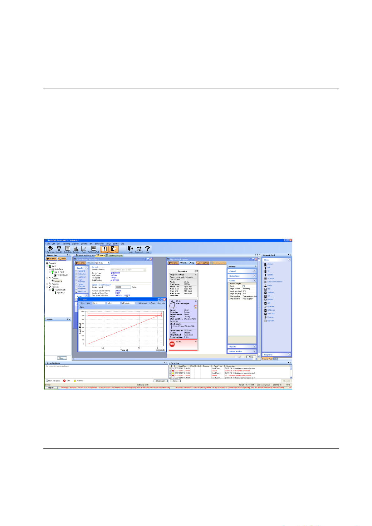
1.1.1 ToolsTalk PowerMACS, the friendly user interface
The new improved ToolsTalk PowerMACS (TTPM) builds on the experiences from the earlier WinTC and
with increased simplicity and flexibility make the user experience more rewarding without loosing any
functionality.
Simplicity has been greatly increased by the introduction of the Basic and Advanced concepts into
ToolsTalk PowerMACS, most functionality is hidden for inexperienced users but available at a mouse-click
for more those who feel they need the extra functionality.
Increased user friendliness by drag & drop functionality.
Full reporting ToolsTalk PowerMACS offers full reporting of tightening results, set values and limits. An
easily adapted annunciator shows the tightening results in read-at-a-glance graphics. The combined
SystemMap shows the tightening status of the bolts and the status of all equipped hardware. The system
provides reports for any chosen parameters, trace curves, and advanced SPC and log files.
User guides Accessible via Hyperlinks, the software includes SetUp Wizards, Tutorials, Tightening
Templates which guide you through the most common tightening sequences, Spare Parts Lists with
drawings and article numbers, service, fault-finding and FAQ functions, and a complete on-line manual.
If you need to configure the system for Ethernet or Fieldbus communication, the PowerMACS 4000 Set
Up Wizards make the task simple.
API for easy access ToolsTalk PowerMACS includes the popular Application Program Interface (API)
enabling the engineer to access data from the Tightening Controller. For example: read and write PLC,
cycle and trace data and store cycle data to media. All internal and external communications are via
Ethernet TCP/IP thin wire 100 Mbit/s.
PowerMACS 4000 can be tailored to any assembly process. A built-in PLC (IEC 61131-3), fully
programmable using the ToolsTalk interface, supports various in-station control requirements.
1.1.2 Intelligent tightening controllers, TCs
PowerMACS 4000 is modular in concept, utilizing the new improved intelligent Tightening Controller (TC)
with state-of-the-art software and a wide range of peripheral support and communication possibilities. The
TC is designed for IP43 and is easy to integrate into a production line as a stand-alone unit or integrated
in a panel.
Even more expanded capacity than it‟s predecessor it is an attractive piece of industrial design, the
PowerMACS 4000 TC is equipped with an impressive amount of memory, more than enough to handle
the Real- Time Operative System, Application Programs and the PLC program.
Tightening controllers are now separated in the Primary Tightening Controller (TC) featuring more
connectability and external communication possibilities and the more basic tightening controller (TC).
One Primary TC (PTC) is configured as a System TC and the rest as Spindle TCs. In a system all Spindle
TCs can be replaced without needing to download the setup once again. One system can include a
maximum of 15 stations. Up to 50 TC's can be connected in one system, controlling 50 nut runners.
16 9836 3521 01

Introduction
Full interchangeability means fewer spare parts are required, maintenance time is reduced and availability
is increased.
All common interfaces All PTC's are designed to interface with Ethernet, the most common Fieldbuses,
and industrial PLCs. The Application Program Interface (API) ensures easy external access to the system.
Peripherals simply added A wide range of peripherals can be connected to the PowerMACS 4000 TC
including printers, bar code readers, operator table, operator annunciators, etc.
Flexible installation The plug-and-play modular design of the TC means maximum installation flexibility.
Series communication in line control and data collection enables the PowerMACS TC's to be discreetly
integrated into the production line by the connection of two cables. The appropriate reporting system and
suitable operator interface can be mounted next to the work area.
9836 3521 01 17

Introduction
1.2 Tightening and Gauging
There are two types of PM4000 products:
PM4000 Tightening
PM4000 Gauging
PM4000 Tightening contains all functions needed for normal tightening of bolts. It can read and write
Tightening setups on disk or a TC. It cannot read or write a Gauging setup.
PM4000 Gauging has all the functions of PM4000 Tightening but also additional functions for gauging
applications. It can read a Tightening setup from file and convert it to a Gauging setup but not vice versa.
1.2.1 Gauging Functions
The following functions are only avaliable if you run PM4000 Gauging:
Step BCT
Step Run to Position
Step Wait, PLC signal addition
Check Delta T
Check Low Spot
Check Pos
Check Peak T, additions
Zones (within step)
Store positions
Backlash compensation
1.2.2 Gauging Applications
PM4000 Gauging can be used for applications where turning and measuring of torque and angle with high
precision is needed. Examples:
Torque To Turn
Valve lash
Indexer
Hub nuts
18 9836 3521 01
Introduction
1
2
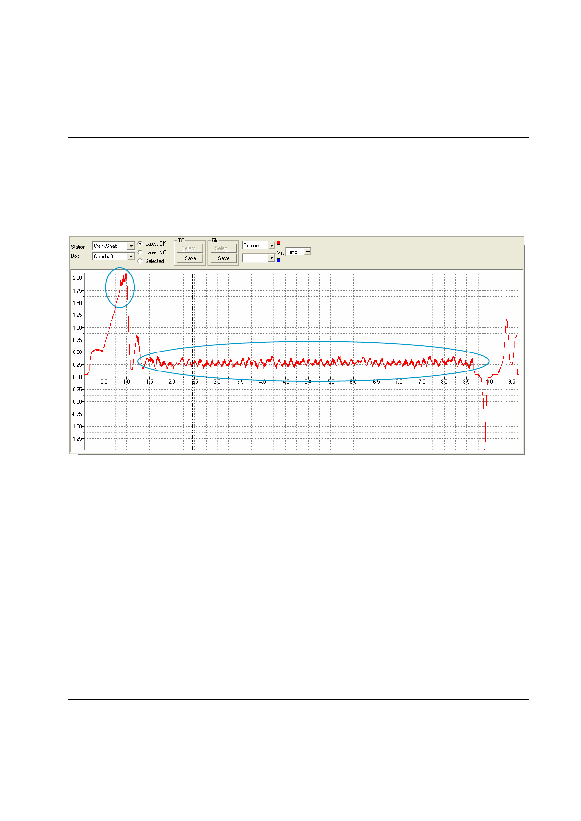
1.2.2.1 Torque To Turn Gauging Application
An example of a Torque To Turn application is when an engine manufacturer wants to rotate the crank or
cam shaft under controlled conditions for the first time. Metal chips, burrs, sharp edges (spot distortions)
may cause excessive drag and eventually lead to early bearing shell failure and warranty repairs.
With PM4000 Gauging it is easy to create a program that rotates the shaft 360 or 720 degrees and
continuously monitor the torque and angle.
The curve present torque vs. time. There are two critical points.
1. Break-Away
2. Low Torque Rotation Test
To check break-away the torque is gently increased without rotation. If the torque reaches a preset limit
before any rotation starts the test stops immediately, preventing any damage.
If the break-away torque is within limits the rotation starts and the torque is monitored for the full rotation at
slow speed. Any friction out of limit indicates mechanical problems that should be corrected.
The combination of the two tests will show up any mechanical problems at a very early stage, before the
motor has been built into e.g. a vehicle. This eliminates the risk that the motor later experience expensive
service warranties.
9836 3521 01 19

Introduction
1.2.2.2 Valve Lash Gauging Application
In a Valve Lash application a bolt and a nut should be rotated and locked to each other to achieve a
specific valve lash. This can be done with a special coaxial spindle, e.g. QMX 42-2RT.
It is easy to create a program that operates the two spindles in a controlled way to make up perfectly
adjusted valve lash.
20 9836 3521 01
Introduction
1.3 Installing ToolsTalk PowerMACS
You can install ToolsTalk PowerMACS from CD or from a hard disk. To install PM4000 Tightening you
excecute the file “PM4000 10.X.X ToolsTalk.exe” located in the folder ToolsTalk. PM4000 Gauging is
installed with the file “PM4000 10.X.X ToolsTalk Gauging.exe” located in the folder ToolsTalk Gauging.
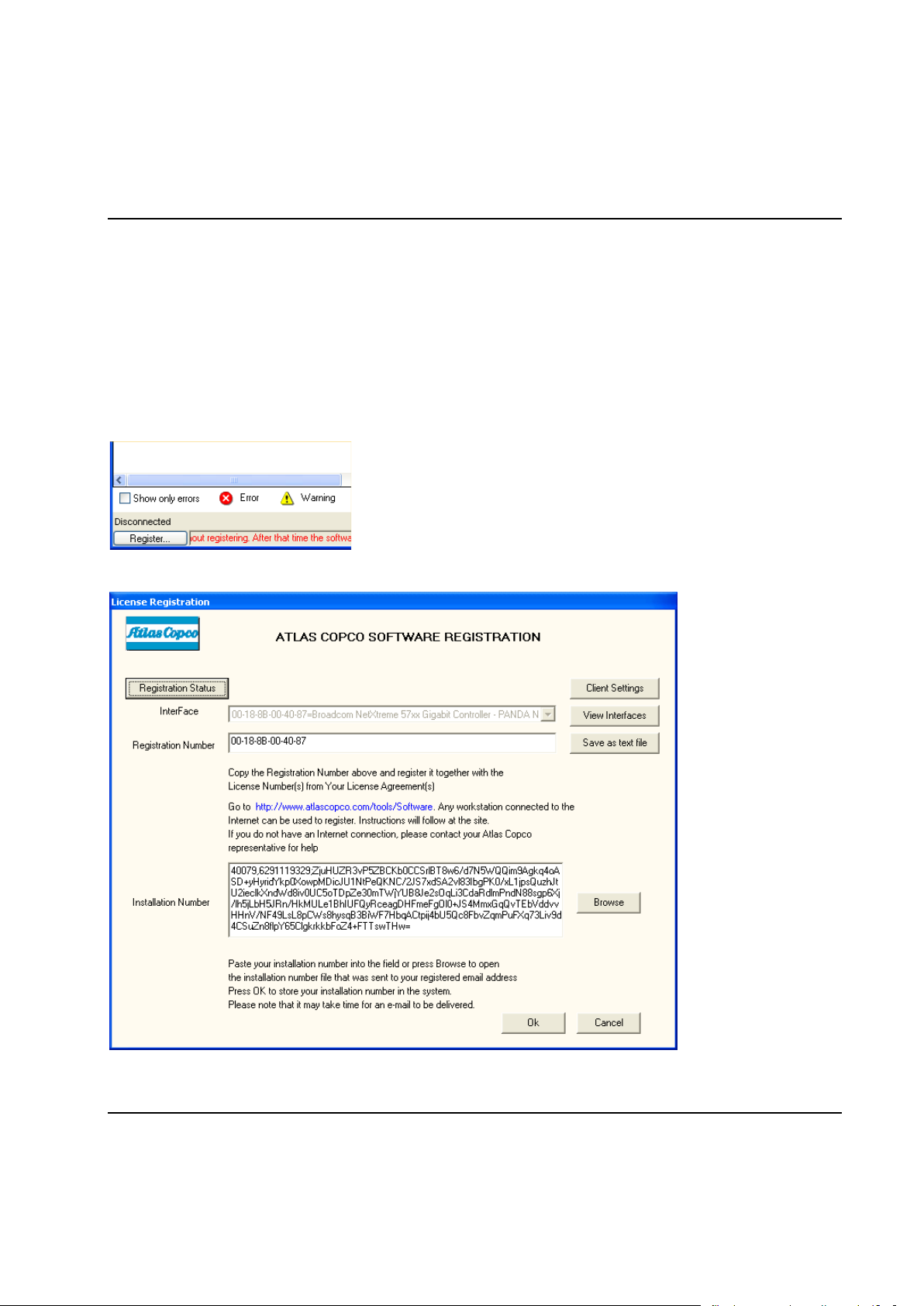
After installing ToolsTalk PowerMACS you have up to 90 days to register it.
Register buttons are found at the bottom left part of the window for an unregistered ToolsTalk, and in the
Help-About window.
To register, press a Register button to invoke the below form, and follow the instructions.
9836 3521 01 21
Introduction
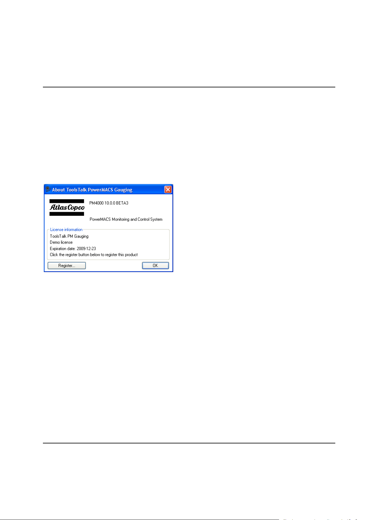
When registering please note that there are two types of products:
PM4000 Tightening
PM4000 Gauging
The license only covers one of the products. For more information on differences between these products
see Tightening and Gauging.
Until registered ToolsTalk PowerMACS will display an extra status bar at the bottom of the main window
showing you the number of days left of the evaluation period. When this time expires the application will
no longer be possible to start and is automatically shut down if it is running.
22 9836 3521 01

System Architecture
2 System Architecture
2.1 System Architecture - Overview
This section describes the architecture of the PowerMACS 4000 system. It includes the descriptions of the
hardware components, including computers and devices, the structures of the system, station and
spindles.
9836 3521 01 23
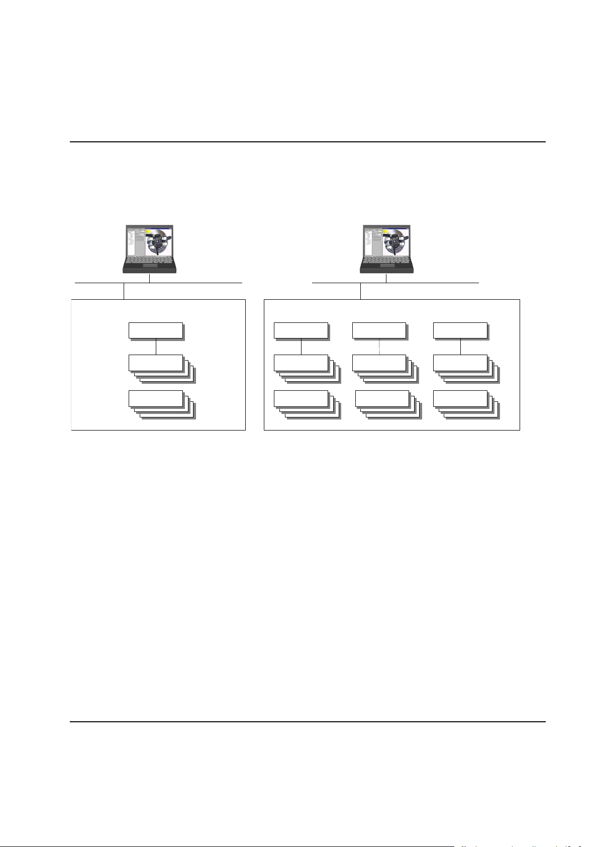
System Architecture
A one station PowerMACS System
Bolt
Station
Spindle
A three station PowerMACS System
Bolt
Station
Bolt
Station
Bolt
Station
Spindle
Spindle
Spindle
2.2 System Structure
A PowerMACS System consists of one or more stations where each station may control one or more
bolts.
System
A system comprises one or more Tightening Controllers linked together. A system works autonomously,
performing the programmed tightening task(s).
ToolsTalk PowerMACS can only connect to one PowerMACS system at the time. This means that the
user cannot edit or display data from two or more systems simultaneously while using one ToolsTalk. If
you need to display data from two or more stations at the same time you must design them in one system.
Multiple PowerMACS systems may be networked together in a single facility but are limited by the number
of available IP addresses. There is no limitation when networking is not used.
One system can contain up to 50 Tightening Controllers and up to 50 Spindles.
Station
Within a system you can have up to 15 stations and 100 Bolts totally. One station can control up to 50
bolts but there must be no more than 100 Bolts in a system. The Station has a PLC to control the
tightening cycles and interface with automation controllers. Cycle data is generated for each Station
consisting of the result of all bolts controlled by the Station.
Bolt
A Bolt is the object that will be tightened by the system. A spindle does the actual tightening.
24 9836 3521 01

System Architecture
Spindle
A Spindle performs the actual tightening task. One Spindle can be used to tighten several Bolts and it
normally comprises of:
Motor
Intelligent CPU with complete measuring system
One or more torque sensors
One or more angle sensors
ToolsTalk
ToolsTalk PowerMACS is a Windows application used to set up a PowerMACS 4000 system. It is not
needed for automatic running, but it can optionally be used to monitor the system and to collect and
display various data.
ToolsTalk PowerMACS can be used for multiple systems, if they are hooked up on the same computer
network, but only one system at a time can be accessed.
9836 3521 01 25
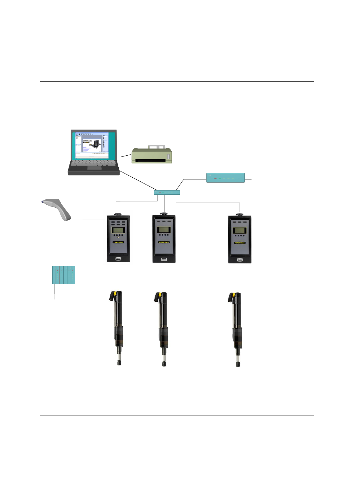
System Architecture
............
TC 1 (primary) TC 2 (secondary) ...... TC n (secondary)
..Sp n
Factory
Network
Ethernet
Field bus
Serial bus
I/O bus
Hub
Router
I/O-module
Peripheral
Peripheral
Console with ToolsTalk
2.3 Hardware Structure
The figure below describes the hardware structure of a PowerMACS 4000 system, i.e. how hardware
components are used.
26 9836 3521 01

System Architecture
2.3.1 Tightening Controller
A Tightening Controller (TC) takes care of various tasks around tightening: driving and controlling a
spindle, measuring and storing angle and torque, running PLC, etc. Each TC contains all functions
necessary to monitor and control one (1) spindle.
Two different Tightening Controllers exist, the PTC is intended to run as a System TC and Station TC. The
PTC has more external interfaces (sockets) than the standard TC.
The System TC is the TC that communicates directly with ToolsTalk PowerMACS. It is on this TC that the
setup, downloaded from ToolsTalk PowerMACS, is stored and is responsible for starting the system when
powered on, or after downloading a new setup.
A single TC belongs to one system only. The System TC, and the setup downloaded to it, defines the
system. When the System TC starts up, either at power on or after receiving a new setup, it will try to
attach to the Spindle TCs it needs. It will assume that IP-address of the Spindle TCs are consecutive to its
own IP-address. That is, if the System TC has address 192.168.0.1 TC 2 should have 192.168.0.2, TC 3
192.168.0.3, and so on.
A Spindle TC will only accept the request of the first System TC that attach to it after a cold start. It will
then remember the IP-address of the System TC and refuse requests from a System TC having another
IP-address until cold started again. See chapter: Configure Target System for more information on how to
configure a TC as a System TC and set its IP-address. Chapter: Configure Target System describes a tool
for detecting overlapping systems, that is, several System TCs trying to use the same Spindle TC.
Spindle TCs can be replaced while the system is operational, without requiring the setup to be
downloaded to the new TC before starting it again. They will fetch their part of the setup from the System
unit when activated.
For security and redundancy a back up copy of the setup is maintained on the second TC in a
PowerMACS 4000 system. This means that the System TC in a system can be replaced without requiring
the setup to be downloaded to the new System TC before starting the system again. See chapter:
Handling of the setup in the target system for details.
Should both the System TC and TC 2 be found nonfunctional and must be replaced then the setup must
be downloaded from a backup media using ToolsTalk PowerMACS. You should therefore always keep
backups of your setups in a safe place.
Note! After replacing the System TC you are strongly recommended to cold start the complete
system.
All TCs in a system, System TCs as well as Spindle TCs, must use the same TC System Software
version in order to function properly. There are several methods to verify that this is the case for all TCs in
a system. The TCs themselves checks for version conflicts at start up and indicates this using the display
on the their front (see chapter: Version conflict message) and ToolsTalk PowerMACS has several forms
that can be used for the same purpose (see chapter: Configure Target System and Check for System
Conflicts).
9836 3521 01 27
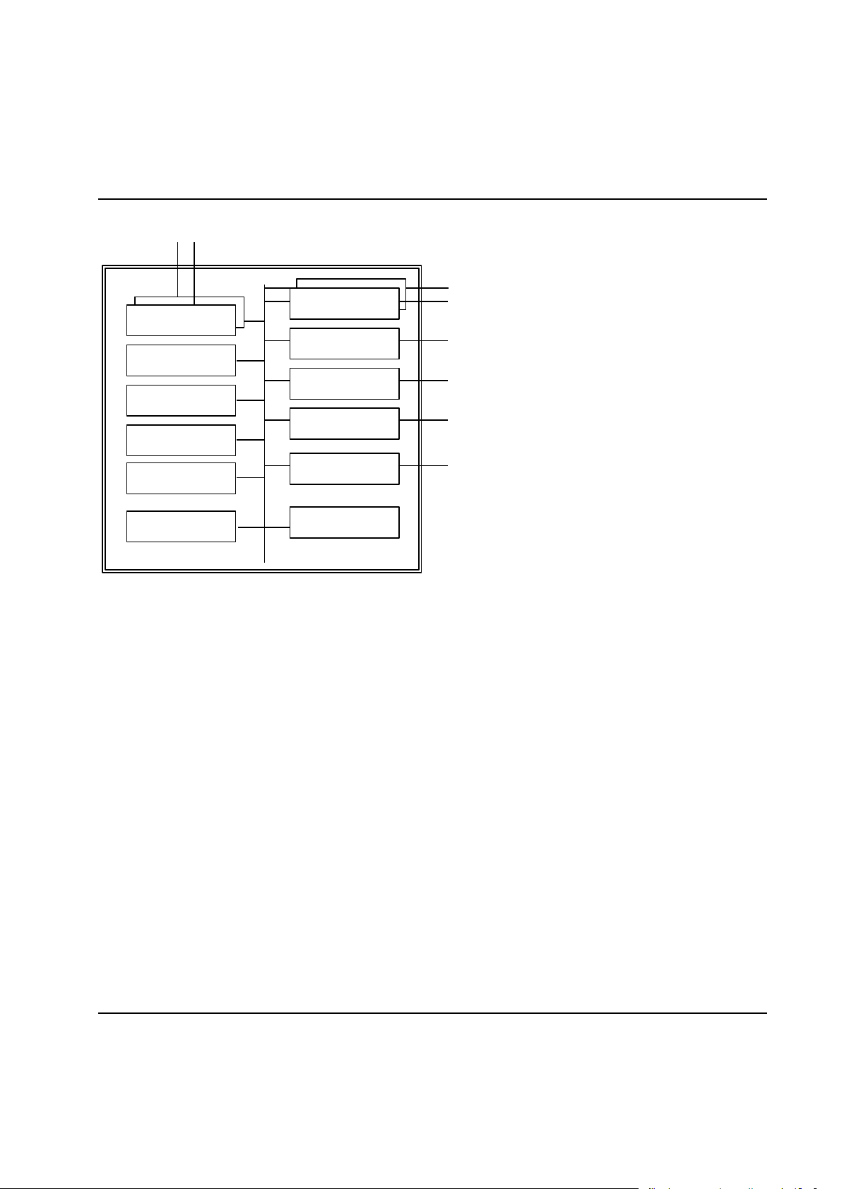
System Architecture
Flash-PROM
RAM
CPU
Local I/O
ST bus
Serial
MACS I/O
Emerg. Stop
SRAM
Ethernet
Battery
RTC
The TC board has the following layout:
28 9836 3521 01

System Architecture
Item
Function
Use
Ethernet
Ethernet interfaces
For communication with other TCs. In System TC:s the
second Ethernet interface is used for communication
with the Consol Computer (ToolsTalk PowerMACS),
100 MBits
CPU
Central Processing Unit
PowerPC 880, 120 MHz
RAM
Random Access Memory
For storage of program and data when executing, 32
MB
Flash-PROM
Programmable Read Only
Memory of Flash type
For storage of boot and application software.
SRAM
Static RAM with battery
backup
For storage of set-ups, traces, cycle data etc.
2 MB
ST bus
St bus (2 ch)
ST bus 1 is for communication with the drive and the
spindle, located in the tool connector. ST bus 2 is for
communication with ST based accessories.
Emerg. stop
Emergency Stop
Class 3 Emergency Stop, breaks the gate drive
voltage.
Local DI
Digital input
Opto Isolated Digital Input
Local DO
Digital Output
Relay Outputs
Serial
Serial interface
Interface to serial devices, 3 channels RS232, 1
channel RS422, 2 channels RS485
MACS I/O
CAN bus interface
Opto Isolated interface to MACS I/O and other
accesories
AnyBus
FieldBus interfaces
Interface to superior devices
Battery
RAM-backup
Expected life length >10 years
RTC
Real Time Clock
Battery backed Real Time Clock
9836 3521 01 29
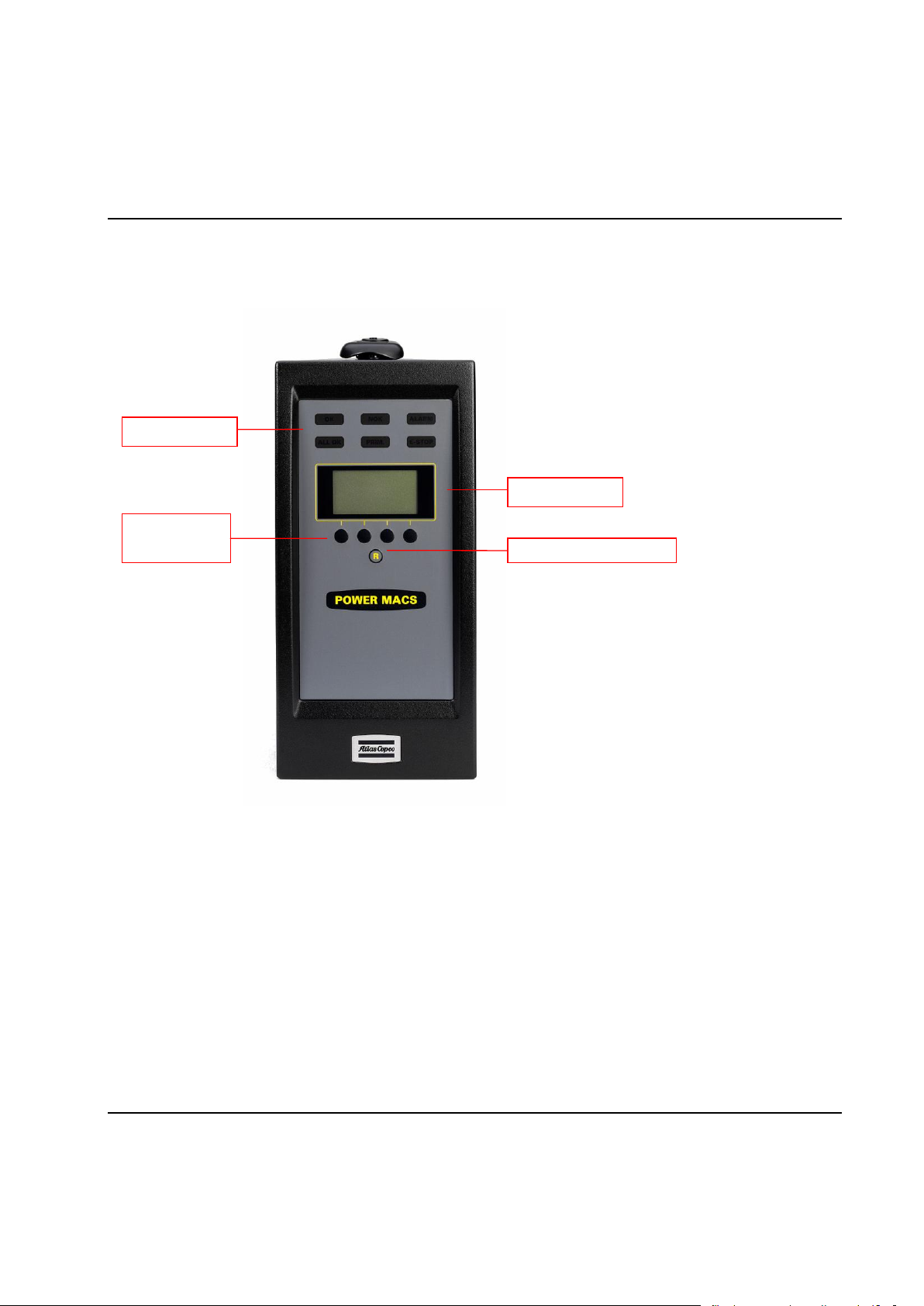
System Architecture
LEDs
HMI
Soft buttons
Reset emergency stop
HMI Display
2.3.1.1 PTC Description
All indicators are located on the front of the PTC:
The following LED indicators can be found on top of the PTC and are common with the LEDs found on
regular TCs.
OK is lit green when last cycle (tightening) performed by the PTC was OK.
NOK is lit red when last cycle (tightening) performed by the PTC was NOK.
ALARM is lit red when a servo or spindle hardware or system error has been detected on the PTC.
To acknowledge the alarm the PLC variable RESET can be used, an attempt to acknowledge the
alarm is also performed automaticly at each cycle start.
The second row of LED indicators can only be found on the PTC.
ALL OK is PTC specific and indicates that the cycle (tightening) for all bolts for the station was OK.
PRIM. Indicates that the PTC is also the System TC for a system.
E-STOP is lit when the station controlled by the PTC is emergency stopped.
30 9836 3521 01
 Loading...