

Atlas Copco Power Focus 4000, Power Focus 3000, Power Focus 3100, Power Focus 3102 User Manual
User guide
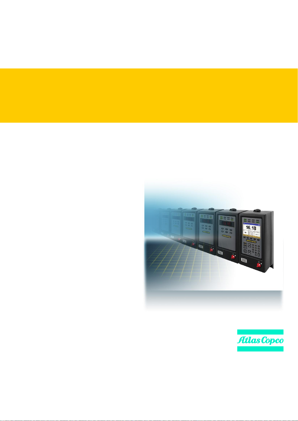
Power Focus
Atlas Copco Industrial Technique AB
9836 3123 01
Software release W10.9 SR3
Edition 18.2
2013-03

Copyright Atlas Copco Tools and Assembly Systems
Note! This manual can be altered without further notice.
For further information log in to Atlas Copco www.atlascopco.com

Contents
Contents
Contents ......................................................................................................................... 3
1 General safety instructions ................................................................................ 11
1.1 Work area .............................................................................................................. 11
1.2 Electrical safety ...................................................................................................... 11
1.3 Personal safety ...................................................................................................... 12
1.4 Service ................................................................................................................... 13
2 Introduction ......................................................................................................... 15
2.1 Revision history ...................................................................................................... 15
2.2 Abbreviations ......................................................................................................... 15
3 Introduction to Power Focus .............................................................................. 17
3.1 PF 4000 ................................................................................................................. 18
3.2 PF 3000/3100/3102 ................................................................................................ 19
3.3 RBU ....................................................................................................................... 20
3.4 ToolsTalk PF .......................................................................................................... 20
3.5 Communication ...................................................................................................... 20
3.6 Tensor tools ........................................................................................................... 22
3.6.1 Tool accessories ...................................................................................................... 23
3.7 Hardware accessories ............................................................................................ 25
3.8 Software accessories ............................................................................................. 27
3.8.1 ATS .......................................................................................................................... 27
3.8.2 ACTA 4000 .............................................................................................................. 28
4 Connecting devices ............................................................................................ 29
4.1 PF connections ...................................................................................................... 29
4.2 RBU ....................................................................................................................... 30
4.2.1 MAC-address ........................................................................................................... 30
4.2.2 PF start-up instructions ............................................................................................ 30
4.3 Tool connection and start-up .................................................................................. 31
4.3.1 Tools with cable connection .................................................................................... 31
4.3.2 Tensor STB.............................................................................................................. 32
4.3.3 Start-up instruction for open-end tools .................................................................... 32
4.3.4 Wireless tools .......................................................................................................... 33
4.3.5 ST GPIO connection ................................................................................................ 33
4.3.6 ST-selector connection ............................................................................................ 34
4.4 Printer .................................................................................................................... 35
4.5 Serial connection .................................................................................................... 35
4.5.1 Serial RS232 #1 ...................................................................................................... 35
4.5.2 Serial RS232 #2 ...................................................................................................... 36
4.6 Ethernet TCP/IP ..................................................................................................... 36
9836 3123 01 3 (428)

Contents
4.7 Digital inputs ........................................................................................................... 36
4.8 Digital outputs (relays) ............................................................................................ 37
4.9 24 VDC output ........................................................................................................ 38
4.10 I/O Bus ................................................................................................................... 38
4.11 Remote start connector .......................................................................................... 39
4.12 Main power connector ............................................................................................ 40
5 PF user interface ................................................................................................. 41
5.1 PF Graph ................................................................................................................ 41
5.1.1 Front panel .............................................................................................................. 41
5.1.2 Display .................................................................................................................... 43
5.1.3 Programming PF Graph .......................................................................................... 44
5.2 PF Compact............................................................................................................ 49
5.2.1 Front panel .............................................................................................................. 49
5.2.2 Display .................................................................................................................... 50
5.2.3 Indicator lights ......................................................................................................... 51
5.2.4 Keypad .................................................................................................................... 52
6 Getting started with ToolsTalk PF ..................................................................... 55
6.1 Installing ToolsTalk PF ........................................................................................... 55
6.2 ToolsTalk overview ................................................................................................. 56
6.2.1 Menu list .................................................................................................................. 56
6.2.2 Selection panel ....................................................................................................... 59
6.2.3 Toolbar .................................................................................................................... 60
6.2.4 PF Map ................................................................................................................... 62
6.3 Configuring ToolsTalk settings ................................................................................ 63
6.3.1 Communication ....................................................................................................... 63
6.3.2 Application .............................................................................................................. 65
6.3.3 Printout .................................................................................................................... 66
6.3.4 PF List ..................................................................................................................... 67
6.4 Connecting a PF ..................................................................................................... 68
6.4.1 Ethernet connection ................................................................................................ 68
6.4.2 Serial connection .................................................................................................... 68
6.4.3 USB connection ...................................................................................................... 69
6.4.4 To connect .............................................................................................................. 70
6.4.5 To disconnect ......................................................................................................... 70
6.4.6 Cordless tools ......................................................................................................... 70
6.5 Storing programming on file .................................................................................... 70
6.5.1 Store PF to file ........................................................................................................ 71
6.5.2 Read PF from file .................................................................................................... 72
6.6 Offline ..................................................................................................................... 73
6.6.1 Configuring a tool offline ......................................................................................... 74
7 Pset....................................................................................................................... 75
7.1 Create new Pset/Open Pset ................................................................................... 76
7.2 Autoset ................................................................................................................... 77
4 (428) 9836 3123 01

Contents
7.3 Quick programming ................................................................................................ 78
7.4 Programming help .................................................................................................. 79
7.5 Programming ......................................................................................................... 80
7.6 Control strategies ................................................................................................... 84
7.6.1 Tq con ...................................................................................................................... 84
7.6.2 Tq con/ang mon ....................................................................................................... 85
7.6.3 Ang con/tq mon ....................................................................................................... 85
7.6.4 Tq con/ang con (AND) / (OR) .................................................................................. 86
7.6.5 Reverse ang ............................................................................................................ 87
7.6.6 Rotate spindle forward/reverse................................................................................ 88
7.6.7 Click wrench ............................................................................................................ 88
7.6.8 Home position forward and reverse ........................................................................ 89
7.6.9 Yield control (Yield) ................................................................................................. 90
7.6.10 Yield/Tq con (OR) .................................................................................................... 90
7.6.11 DS con ..................................................................................................................... 91
7.6.12 DS con/tq mon ......................................................................................................... 92
7.6.13 Snug gradient .......................................................................................................... 93
7.6.14 PVT comp with snug ................................................................................................ 94
7.7 Tightening strategies .............................................................................................. 95
7.7.1 One stage ................................................................................................................ 96
7.7.2 Two stage ................................................................................................................ 96
7.7.3 Quick step ................................................................................................................ 97
7.7.4 Ergo ramp ................................................................................................................ 98
7.7.5 Additional control options ........................................................................................ 98
7.7.6 Rehit detection ......................................................................................................... 99
7.8 Programming + ...................................................................................................... 99
7.8.1 Current monitoring ................................................................................................. 100
7.8.2 PVT selftap ............................................................................................................ 101
7.8.3 PVT monitoring ...................................................................................................... 102
7.8.4 PVT compensate ................................................................................................... 104
7.8.5 Options .................................................................................................................. 105
7.8.6 Gradient monitoring ............................................................................................... 106
7.8.7 Yield control ........................................................................................................... 107
7.8.8 Post view torque .................................................................................................... 109
7.9 Pset setup ............................................................................................................ 110
7.10 Statistic programming ........................................................................................... 112
7.11 Running a Pset..................................................................................................... 112
8 Multistage .......................................................................................................... 113
8.1 Create new Multistage/Open Multistage ............................................................... 114
9 Job ...................................................................................................................... 117
9.1 Job concepts ........................................................................................................ 117
9.2 Job configuration ................................................................................................ .. 119
9.2.1 Creating a Job group ............................................................................................. 119
9836 3123 01 5 (428)

Contents
9.2.2 Creating a new Job ............................................................................................... 120
9.2.3 Select Job ............................................................................................................. 122
9.3 Functions in the Job monitor ................................................................................. 124
9.4 Unlock the tool ................................................................ ...................................... 125
10 Controller ........................................................................................................... 126
10.1 Information ........................................................................................................... 126
10.2 Configuration ........................................................................................................ 128
10.3 Network ................................................................................................................ 130
10.3.1 Cell and Net configuration .................................................................................... 132
10.4 COM ports ............................................................................................................ 136
10.5 Display.................................................................................................................. 137
10.6 Memory ................................................................................................................ 138
10.7 Accessibility .......................................................................................................... 141
11 Tool..................................................................................................................... 143
11.1 Tool information .................................................................................................... 143
11.2 Tool configuration ................................................................................................. 145
11.2.1 Tool start and Accessory bus ............................................................................... 145
11.2.2 Sound and buzzer ................................................................................................. 147
11.2.3 Tool function buttons ............................................................................................ 149
11.2.4 Blue LED ............................................................................................................... 151
11.2.5 Tool illuminator and lights ..................................................................................... 152
11.2.6 Radio and Connection .......................................................................................... 153
11.3 Tool diagnostic ..................................................................................................... 154
11.3.1 Sensor tracking ..................................................................................................... 155
11.3.1 Transducer calibration .......................................................................................... 155
11.4 Tool maintenance ................................................................................................. 157
11.4.1 Calibration and Service ......................................................................................... 158
11.4.2 Open-end tuning ................................................................................................... 158
11.4.3 Wear indicator ....................................................................................................... 160
11.4.4 ACTA .................................................................................................................... 160
11.4.5 Motor tuning .......................................................................................................... 161
11.4.6 Disconnect tool ..................................................................................................... 162
11.4.7 Hot swap ............................................................................................................... 164
11.5 Tool lock functionality ........................................................................................... 164
11.5.1 Locking of tools from an external source in time critical applications ................... 164
11.5.2 Intentional locking of tools .................................................................................... 165
11.5.3 Definition of a locked tool ...................................................................................... 165
11.5.4 Tool locking event codes ...................................................................................... 165
12 Accessories ....................................................................................................... 167
12.1 Digital I/O .............................................................................................................. 167
12.2 I/O bus .................................................................................................................. 170
12.3 Tool bus ................................................................................................................ 175
6 (428) 9836 3123 01

Contents
12.4 Printer .................................................................................................................. 178
13 Sync ................................................................................................................... 181
13.1 Sync prerequisites and limitations ........................................................................ 182
13.2 Hardware configuration ........................................................................................ 183
13.3 Sync configuration ................................................................................................ 184
13.3.1 Sync members configuration ................................................................................. 184
13.3.2 Sync reference configuration ................................................................................. 185
13.4 Troubleshooting ................................................................................................... 187
14 Identifier ............................................................................................................. 189
14.1 Identifier concepts ................................................................................................ 189
14.2 Identifier prerequisites and details ........................................................................ 190
14.3 Configuration of identifier functions ...................................................................... 192
14.3.1 Configuring identifiers ............................................................................................ 193
14.3.2 Configuring a work order ....................................................................................... 195
14.3.3 Configuring result parts ......................................................................................... 196
14.3.4 Additional identifier functions ................................................................................. 197
15 Fieldbus ............................................................................................................. 199
15.1 General setup ...................................................................................................... 200
15.1.1 Parameters in General setup ................................................................................. 201
15.1.2 View fieldbus information ....................................................................................... 203
15.2 From PF setup and to PF setup ........................................................................... 204
15.2.1 Fieldbus modes ..................................................................................................... 205
15.3 Storing fieldbus configuration ............................................................................... 206
15.4 Disable fieldbus carried signals ............................................................................ 206
15.5 Fieldbus data format ............................................................................................ 207
15.5.1 Bitmap select (Endian mode) ................................................................................ 207
15.5.2 Fieldbus data types ............................................................................................... 207
15.6 Fieldbus selector configuration ............................................................................. 212
15.7 Select Pset from fieldbus and set batch size ........................................................ 213
15.8 Fieldbus information ............................................................................................. 214
15.8.1 ProfiBus-DP ........................................................................................................... 214
15.8.2 DeviceNet .............................................................................................................. 218
15.8.3 InterBus/InterBus2MB ........................................................................................... 223
15.8.4 ModBusPlus........................................................................................................... 227
15.8.5 Ethernet/IP ............................................................................................................. 231
15.8.6 Modbus/TCP .......................................................................................................... 233
15.8.7 ControlNet .............................................................................................................. 234
15.8.8 Profinet .................................................................................................................. 236
15.8.9 FL-Net .................................................................................................................... 238
15.8.10 CC-Link .................................................................................................................. 239
16 Logic Configurator ............................................................................................ 245
16.1 Process description (an example) ........................................................................ 246
9836 3123 01 7 (428)

Contents
16.2 Logic operators and function blocks ...................................................................... 247
16.2.1 Logic gates............................................................................................................ 247
16.2.2 Function blocks ..................................................................................................... 248
16.3 Logic Configurator setup ....................................................................................... 251
16.3.1 Simulation ............................................................................................................. 256
17 Monitors ............................................................................................................. 259
17.1 Result Monitor ...................................................................................................... 260
17.2 Job Monitor ........................................................................................................... 262
17.3 Operator Monitor .................................................................................................. 263
17.3.1 Picture Monitor ...................................................................................................... 266
17.4 Identifier Monitor ................................................................................................... 267
17.5 Get all results ........................................................................................................ 268
18 Trace................................................................................................................... 271
18.1 The trace window ................................................................................................. 271
19 Statistics ............................................................................................................ 275
19.1 Statistic alarm ....................................................................................................... 276
19.2 Trend deviation alarm ........................................................................................... 277
19.3 Calculation of UCL and LCL ................................................................................. 277
19.4 Calculation of mean values ................................................................................... 277
19.5 Calculation formulas ............................................................................................. 278
19.6 Constants for calculation of SPC variables ........................................................... 280
20 Quick reference guide....................................................................................... 281
20.1 Tq con .................................................................................................................. 282
20.1.1 One stage ............................................................................................................. 282
20.1.2 Two stage ............................................................................................................. 283
20.1.3 Quick step ............................................................................................................. 284
20.1.4 Ergo ramp ............................................................................................................. 285
20.2 Tq con/ang mon .................................................................................................... 286
20.2.1 One stage ............................................................................................................. 286
20.2.2 Two stage ............................................................................................................. 287
20.2.3 Quick step ............................................................................................................. 288
20.2.4 Ergo ramp ............................................................................................................. 289
20.3 Tq con/ang con (AND) and Tq con/ang con (OR) ................................................. 290
20.3.1 One stage ............................................................................................................. 290
20.3.2 Two stage ............................................................................................................. 291
20.3.3 Quick step ............................................................................................................. 292
20.3.4 Ergo ramp ............................................................................................................. 293
20.4 Ang con/tq mon .................................................................................................... 294
20.4.1 One stage ............................................................................................................. 294
20.4.2 Two stage ............................................................................................................. 295
20.4.3 Quick step ............................................................................................................. 296
20.4.4 Ergo ramp ............................................................................................................. 297
8 (428) 9836 3123 01

Contents
20.5 Reverse ang ......................................................................................................... 298
20.6 Rotate spindle forward and Rotate spindle reverse .............................................. 299
20.7 Home position forward and reverse ...................................................................... 300
20.8 DS con ................................................................................................................. 301
20.8.1 One stage .............................................................................................................. 301
20.8.2 Two stage .............................................................................................................. 301
20.8.3 Quick step .............................................................................................................. 302
20.8.4 Ergo ramp .............................................................................................................. 303
20.9 Snug gradient ....................................................................................................... 304
20.9.1 One stage .............................................................................................................. 304
20.9.2 Two stage .............................................................................................................. 305
20.9.3 Quick step .............................................................................................................. 306
21 Digital I/O and fieldbus items ........................................................................... 307
21.1 Digital output (relay) and fieldbus items from PF .................................................. 307
21.2 Digital input and fieldbus items to PF ................................................................... 328
22 Parameter list .................................................................................................... 341
22.1 Pset ...................................................................................................................... 341
22.1.1 Programming ......................................................................................................... 341
22.1.2 Programming + ...................................................................................................... 346
22.1.3 Pset setup .............................................................................................................. 350
22.1.4 Statistic programming ............................................................................................ 350
22.2 Multistage ............................................................................................................. 353
22.2.1 Setup ..................................................................................................................... 353
22.2.2 Multistage programming ........................................................................................ 354
22.3 Job ....................................................................................................................... 356
22.3.1 Setup ..................................................................................................................... 356
22.3.2 Programming ......................................................................................................... 357
22.4 Controller ............................................................................................................. 360
22.4.1 Information ............................................................................................................. 360
22.4.2 Configuration ......................................................................................................... 361
22.4.3 Network .................................................................................................................. 362
22.4.4 COM ports ............................................................................................................. 364
22.4.5 Display ................................................................................................................... 364
22.4.6 Memory .................................................................................................................. 365
22.4.7 Accessibility ........................................................................................................... 366
22.5 Tool ...................................................................................................................... 366
22.5.1 Information ............................................................................................................. 366
22.5.2 Configuration ......................................................................................................... 367
22.5.3 Diagnostic .............................................................................................................. 371
22.5.4 Maintenance .......................................................................................................... 371
22.5.5 Buzzer configuration .............................................................................................. 374
22.5.6 Sound configuration ............................................................................................... 374
22.6 Accessories .......................................................................................................... 375
9836 3123 01 9 (428)

Contents
22.6.1 Digital I/O .............................................................................................................. 375
22.6.2 I/O bus .................................................................................................................. 376
22.6.3 Tool bus ................................................................................................................ 377
22.6.4 Printer ................................................................................................................... 377
22.7 Sync ..................................................................................................................... 377
22.7.1 Programming ........................................................................................................ 377
22.8 Identifier ................................................................................................................ 378
22.8.1 Identifier setup ...................................................................................................... 378
22.9 Fieldbus ................................................................................................................ 379
23 Event codes ....................................................................................................... 383
23.1 Event code list ................................................................ ...................................... 385
23.1.1 E001-E099 Rundown failures ............................................................................... 386
23.1.2 E100-E199 Event related errors ........................................................................... 387
23.1.3 E200-E299 User input events ............................................................................... 398
23.1.4 E300-E399 Statistical events ................................................................................ 401
23.1.5 E400-E499 Communication events ...................................................................... 405
23.1.6 E500-E599 Hardware events (tools) .................................................................... 409
23.1.7 E600-E699 Hardware events................................................................................ 415
23.1.8 E700-E799 Hardware events................................................................................ 416
23.1.9 E800-E899 Software events ................................................................................. 418
23.1.10 E900-E999 Events MMI ........................................................................................ 421
24 Index ................................................................................................................... 422
10 (428) 9836 3123 01

General safety instructions
Ensure that you read and understand all instructions. Failure to follow all the instructions listed below may
result in electric shock, fire and/or serious personal injury. All locally legislated safety regulations with
regard to installation, operation and maintenance must be adhered to at all times. Refer installation and
servicing to qualified personnel only.
Keep the work area clear and well illuminated. Cluttered benches and unlit areas invite accidents.
Do not operate power tools in explosive atmospheres, such as in the presence of flammable liquids, gases, or
dust. Power tools create sparks, which may ignite dust or fumes.
Keep bystanders, children, and visitors at a safe distance while operating a power tool. Distractions may
cause you to lose control.
Earthed tools must be plugged into a socket that has been properly installed and earthed according to
appropriate regulations. Never remove the earth pin or modify the plug in any way. Do not use any adapter
plugs. Check with a qualified electrician if you are in any doubt as to whether the outlet is properly earthed.
Should the tools suffer electronic malfunction or breakdown, the earth provides a low resistance path to
carry electricity away from the user. Applicable only to Class I (earthed) tools.
This apparatus must be earthed.
A Power Focus (PF) cannot be fitted with a galvanic isolated voltage as this would inhibit the function of
the Ground Fault Interrupter (GFI). The test button on the GFI also activates the GFI in instances where a
PF is equipped with an isolated transformer. Test the earth fault protector by pressing the test button located
on the rear panel of PF.
Test the earth protector every month by pressing the test button. Should the earth fault protector disconnect
the system, be sure to find the primary reason before you resume operation.
Avoid physical contact with grounded surfaces such as pipes, radiators, ovens and refrigerators. There is an
1 General safety instructions
1.1 Work area
1.2 Electrical safety
9836 3123 01 11 (428)

General safety instructions
increased risk of electric shock if your body is grounded.
Do not expose power tools to rain or wet conditions. Water entering a power tool will increase the risk of
electric shock. This instruction does not apply to tools classified as watertight or splash proof.
For minimum electrical interference, locate the controller as far as possible from sources of electrical noise,
e.g. arc welding equipment etc.
Do not abuse the power lead. Never use the power lead to carry the tool or to pull the plug from a socket.
Keep the power lead away from heat, oil, sharp edges or moving parts. Replace damaged leads immediately.
Damaged leads increase the risk of electric shock.
Stay alert, watch what you are doing and use common sense when operating a power tool. Do not use a tool
while tired or under the influence of drugs, alcohol, or medication. A momentary lapse in concentration
whilst operating power tools may result in serious personal injury.
Dress properly. Do not wear loose clothing or jewelry. Tie long hair back. Keep your hair, clothing, and
gloves away from moving parts. Loose clothes, jewelry, or long hair can become caught in moving parts.
Avoid accidental starting. Ensure switches are in the off position before plugging in. Carrying a tool with
your finger on the switch or plugging in a tool that has the switch set to “On” is inviting an accident.
Remove adjusting keys or switches before turning the tool on. A wrench or a key that is left attached to a
rotating part of the tool could lead to personal injury.
Do not overreach. Keep proper footing and balance at all times. Proper footing and balance enables better
control of the tool in unexpected situations.
Use clamps or other practical means to secure and support the work piece to a stable platform. Holding the
work by hand or against your body is unstable and may lead to loss of control.
Do not force the tool. Use the correct Atlas Copco Tensor tool for your application. The correct tool will do
the Job better and more safely in a manner for which it was designed.
Do not use a tool if the switch does not work. Any tool that cannot be controlled by the switch is dangerous
and must be repaired.
Disconnect the plug from the power source before making any adjustments, changing accessories, or storing
the tool. Such preventive safety measures reduce the risk of the tool starting accidentally. The mains plug is
considered to be a disconnecting device. Disconnect the tool from the mains by removing the plug from the
socket in order to cut the power.
Store tools out of the reach of children and other untrained persons when not in use. Tools are dangerous in
1.3 Personal safety
12 (428) 9836 3123 01

General safety instructions
the hands of untrained users.
Check for misalignment, obstruction of moving parts, damage, and any other condition that may affect tool
operation. If damaged, have the tool serviced before using. Poorly maintained tools cause many accidents.
Only use accessories that are recommended by the manufacturer for your model. Accessories that may be
suitable for one tool may become hazardous when used on another tool.
Tools should only be serviced by qualified repair personnel. Service or maintenance performed by
unqualified personnel could expose users to serious personal injury.
When servicing a tool, only use original replacement parts. Use of unauthorized parts or failure to follow
maintenance instructions may lead to electric shock or personal injury.
Always refer to the Product Information for PF4000 (9836 3113 00) and Product Information for PF3000 (9836 2156
01) for spare parts and instructions, and Atlas Copco spare part list for the tool used.
There is a risk of explosion if batteries are incorrectly replaced. Replace only with the same
or equivalent type recommended by the equipment manufacturer. Discard used batteries in
accordance with the manufacturer's instructions.
1.4 Service
9836 3123 01 13 (428)


Introduction
Abbreviation
Description
R
The center line
X
The mean
X
The mean of the average
<= =>
Arrow (button)
Sigma (standard deviation)
α
Alpha (often a symbol for angle)
µ
Mu (the values of the mean)
%
Percent
A
Ampere
AC
Alternating Current
ACK
Acknowledged
Admin
Administration
Ang con
Angle control
Ang mon
Angle monitoring
bits/s
Bits per second
Abbreviation
Description
CAN
Controller Area Network
CC
Control Card
CCW
Counter-Clockwise
CD
Compact Disc
Ch
Channel
CL
Clear (button)
Config
Configuration
CW
Clockwise
DC
Direct Current
Deg
Degrees
Deg C
Degrees centigrade
DigIn
Digital Input
DigOut
Digital Output (relay)
DSP
Digital Signal Processor
ft.lb
Foot-pound
GFI
Ground Fault Interrupter
HW
Hardware
2 Introduction
This manual describes the Power Focus (PF) controller and how to configure it using ToolsTalk PF.
The first sections describe PF with hardware and software accessories, how to connect, and the user
interface.
The main part of the user guide describes how to use the ToolsTalk PF software to configure PF.
The last part of the user guide lists the parameters and event codes used in PF.
2.1 Revision history
Apart from editorial updates, this manual has been revised as follows.
Updates to reflect functional changes: Contact Atlas Copco for a release description for the current
release.
2.2 Abbreviations
9836 3123 01 15 (428)

Introduction
Abbreviation
Description
Hz
Hertz (unit of frequency)
I/O
Input/Output
ID
Identification
in.lb
Inch-pound
IR
Infra-Red
IRC
Industrial Radio Communication
kpm
Kilo pound meter
LCD
Liquid Crystal Display
LED
Light Emitting Diode
LCK
Tool Locked
LCL
Lower Control Limit
MC
Motor Card
ms
millisecond
n
Number (of values)
Nm
Newton meter
No.
Number
NOK
Not approved (tightenings)
nxOK
Number of approved (tightenings)
OK
Approved (tightenings)
PF
Power Focus
PFNR
Power Focus Not Ready (PF not ready)
PLC
Programmable Logic Controller
PROG
Program (button)
Pset
Parameter set
PVT
Prevailing Torque
Abbreviation
Description
R chart
Range chart
RAM
Random Access Memory
RAS
Remote Access Server
RBU
Rapid Backup Memory
rpm
Revolutions per minute
RS232
Serial communication link
S4/S7/S9
Motor sizes in Tensor S tools
sec
second
SPC
Statistic Parameter Control
STAT
Statistic (button)
SW
Software
TNR
Tool not ready
Tq
Torque
Tq con
Torque control
Tq mon
Torque monitoring
TTPF
Tools Talk Power Focus (SW)
UCL
Upper Control Limit
UTL
Upper Tolerance Limit
V
Volt
VIN
Vehicle Identification Number
X-bar
The mean
X-bar-bar
The average of means
z
subgroup size, group size
16 (428) 9836 3123 01
Introduction to Power Focus
This manual handles the ToolsTalk PF but is also applicable for Power Focus Graph. When
programming on a Power Focus Graph display, we refer to the corresponding section in
ToolsTalk PF.
3 Introduction to Power Focus
Power Focus is the latest generation of control and monitoring systems for advanced tightening
technology. The system is designed for the modern assembly industry with high demands and stringent
quality and efficiency requirements, and offers full modularity through the combination of hardware and
software.
This section includes an overview of the system, and a brief description of the options and accessories. For
more information about the available system parts and their functionality, contact your Atlas Copco
representative and consult the relevant user guide or catalog.
9836 3123 01 17 (428)

Introduction to Power Focus
PF 4000 Graph has an easy-to-read LCD color display.
Statistical data is collected, analyzed and presented on the
screen. Changes and trends in the assembly process are
indicated by diagnostics and statistical alarms, such as SPC
monitor charts and capability (Cpk) alarms. Alpha-numeric
keys allow on-unit setup and easy checking of traces and
statistics. PF 4000 Graph model has a very compact design,
and a standardized mounting plate ensures easy installation
at every workstation.
Completing the range, PF 4000 Compact has a basic operator
interface with six-button keyboard and LED display. Preprogrammed using ToolsTalk PF and with a PC as the
interface, it offers the same functionality as the Graph
model.
PF 4000 Compact
PF 4000 Graph
For technical data, dimensions drawings, connections and spare parts list,
see Product Information for PF4000 (9836 3113 00)
3.1 PF 4000
PF 4000 is a new generation of control systems suitable for most Tensor tools. Unlike its predecessor,
PF 3100, PF 4000 is available in one model with two versions (Compact and Graph) that can handle all
torque levels.
Advanced control functions built into Power Focus 4000 prevent the operator from deviating from the
required process. When it receives assembly information, the programmed Job function automatically
selects the correct tightening sequence and parameters. When combined with barcode scanning for
component identification, the Job function offers traceable, zero-fault process control.
The controller is equipped with a USB connector for laptop access. It is located on the front of the unit for
maximum accessibility. Communication is also possible over serial RS232, Ethernet TCP/IP and various
fieldbus types.
18 (428) 9836 3123 01
Introduction to Power Focus
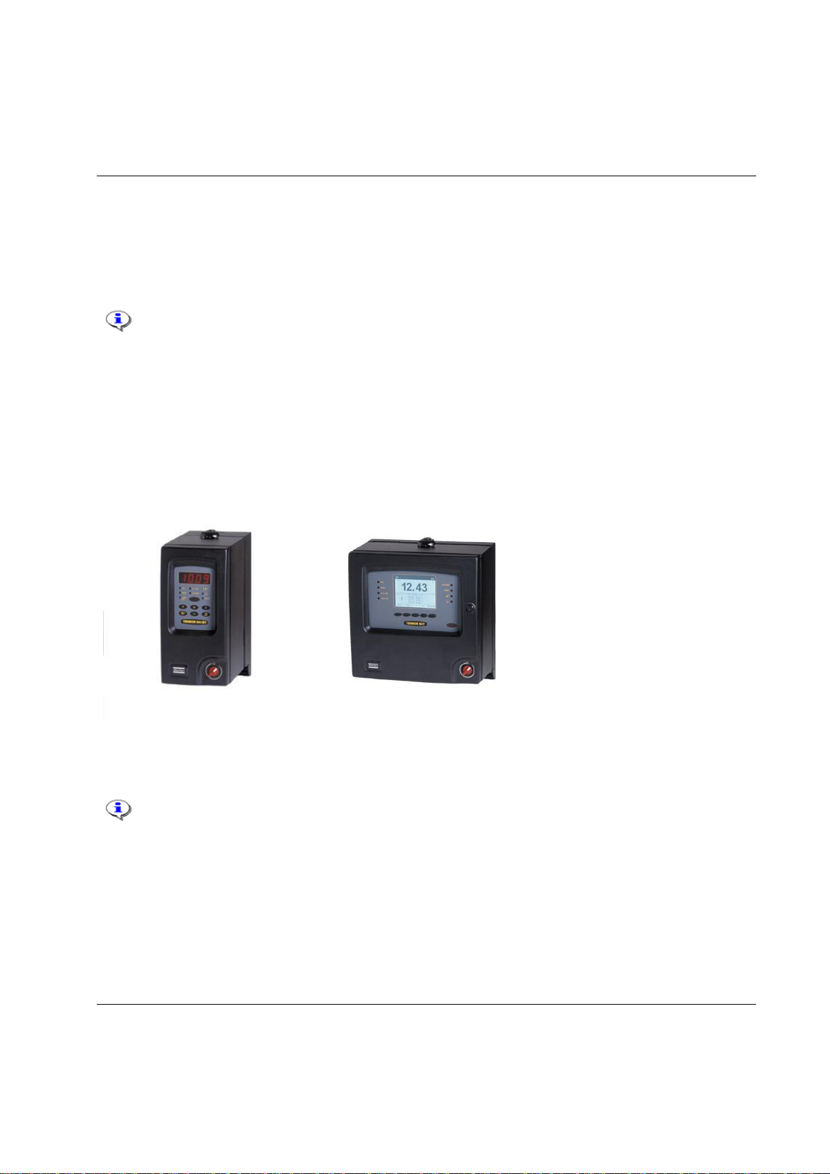
The PF 3000 is a control system for Atlas Copco Tensor S and DS tools. PF 3100 is a control system for
Atlas Copco Tensor ST tools (including functionality for S and DS tools). PF 3102 is the control system
for Atlas Copco Tensor SL tools.
Tensor STB tools require a communication kit to work with Power Focus 3100. The kit
consists of a serial port adapter (access point); cable connector (supplies the serial port
adapter with power).
Two different hardware units are available, Graph and Compact.
PF 3000 Compact offers minimum hardware expenditure and is easily stackable for multiple tool
configurations. PF 3000 Graph models offer full stand-alone programming via an integrated keyboard and
large display located on the front panel of the unit. PF Graph can also be used as a terminal for one or
more PF Compact controllers.
PF 3000 Compact
PF 3000 Graph
For technical data, dimensions drawings, connections and spare part list, see Product
Information for PF3000 (9836 2156 01).
For PF 3102 controllers (SL tool drivers) only the Compact model is available.
3.2 PF 3000/3100/3102
9836 3123 01 19 (428)

Introduction to Power Focus
RBU (Rapid Backup Unit) unlocks a specified level of functionality and acts as a back-
up unit for the configuration of PF. There are different types of RBU; Gold, Silver,
Bronze, X (for ETX tool functionality) and DS (for Tensor DS tool functionality). The
RBU Gold unlocks the full capacity and functionality of the Power Focus. Combine the
RBU giving the required functionality with the chosen hardware.
For a list of the current RBU functionality, contact your Atlas Copco representative.
When an RBU is plugged in to an empty PF, the RBU configuration is transferred to the controller. This
allows the quick installation and replacement of controllers on the assembly line.
ToolsTalk PF, a PC software package developed by Atlas Copco, offers easy and user-friendly
programming and real time monitoring of Power Focus units. ToolsTalk PF is based on extensive
experience and thorough analysis of existing manufacturing industry needs.
ToolsTalk PF can be installed on standard PCs running Windows XP, Windows 7 (32-bit), or Windows 7
(64-bit)
1
and communicates with PF via the serial port or via Ethernet TCP/IP. The real time monitoring
functions include access to Cpk, Traces, Operator monitor, etc.
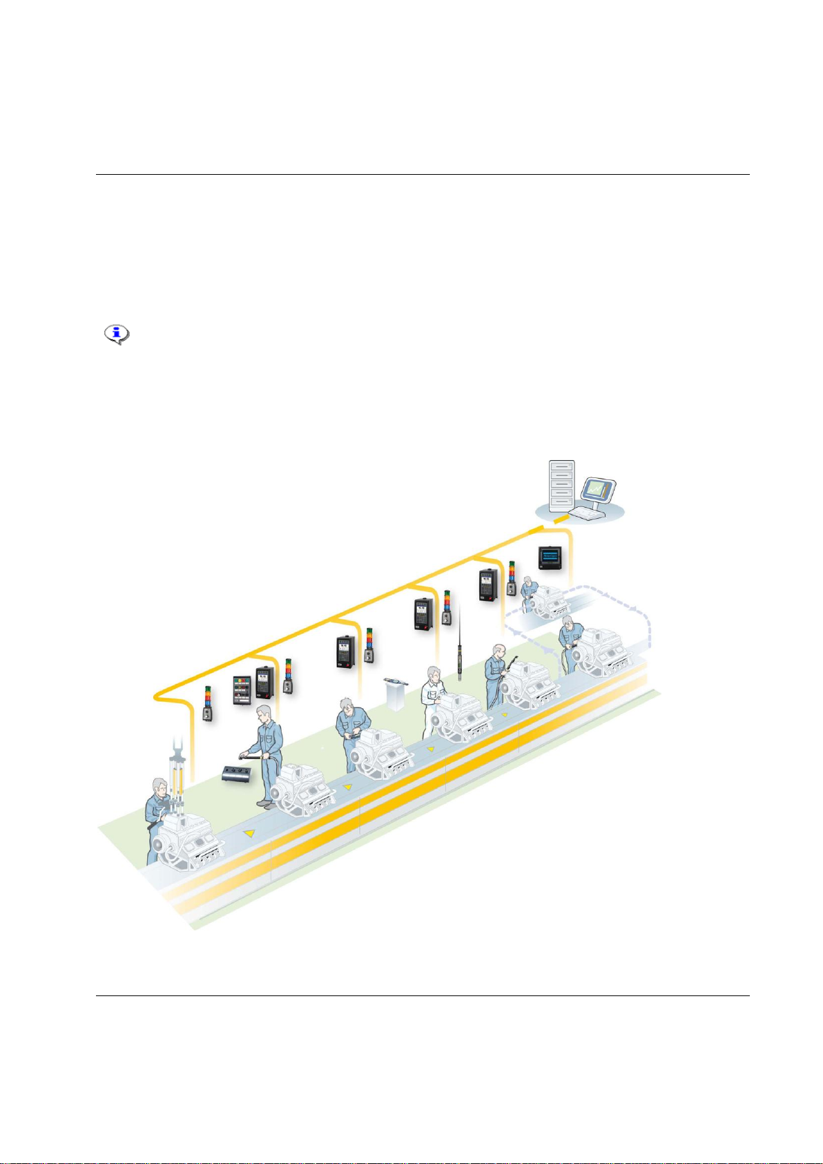
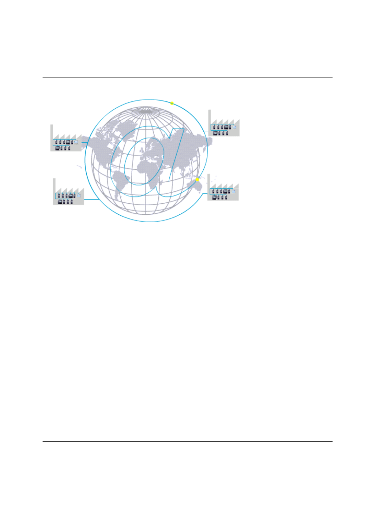
Built-in communication provides efficient use of modern communication technologies with Atlas Copco
products. The Power Focus system can be built to suit the user’s needs, from a simple system offering
many functions, to a complete factory system. Using open standards like TCP/IP, it is possible to connect
and communicate with external systems and allows global communication.
1
3.3 RBU
3.4 ToolsTalk PF
3.5 Communication
Windows is a registered trademark of Microsoft Corporation in the United States and other countries.
20 (428) 9836 3123 01
Introduction to Power Focus
Communicate with one PF at a time via the serial connection or with a complete network of PF units via
the built-in TCP/IP connection.
Power Focus communicates with a range of accessories via the internal I/O bus. PF units and accessories
can be combined according to the customer’s requirements.
The Power Focus can be configured to communicate via the most common buses on the market; ProfiBus,
DeviceNet, InterBus, etc. Real time communication is done over a proprietary I/O bus for tool
synchronization. Several outputs can be activated for communication with PLC’s and other external
equipment. Each PF has four relay contacts, four optic isolated inputs and a 24 V DC / 1 A internal power
supply for external control circuits. All inputs and outputs can be configured using the ToolsTalk PF
software. The number of digital inputs and outputs can be increased using an I/O Expander on the I/O
bus.
With Power Focus, full networking capability is available in the controller as an integrated function, in
relation to both hardware and software. ToolsNet is Windows NT compatible, which offers easy to use,
effective database and data collection functions, using standard databases like SQL, Oracle and Microsoft
Access. PF can be connected to a network for central programming and data collection using ToolsNet.
With the modular concept, the Power Focus is the building block used to create complete and cost
efficient solutions that satisfy the various needs of modern industrial assembly operations.
9836 3123 01 21 (428)

Introduction to Power Focus
Tensor STB communicates with the tightening controller systems through wireless digital communication,
built on IRC (Industrial Radio Communication) technique.
Tensor ST tools communicate with controllers through digital communication, allowing new tool features
and greater flexibility due to not so many wires and leads. Compared with a Tensor S tool, it is also
lighter with improved accessibility.
Tensor SL is a range of low torque transducerized tools based on Tensor ST technology.
Tensor S tools are available in different configurations and motor types. Fixtured applications can easily
be installed and integrated with standard Atlas Copco components.
The ultra-compact ETX tool is designed for fixtured applications.
Atlas Copco’s Tensor DS tools have no transducer. Instead of receiving an electrical signal from a strain
gauge, the tool derives the torque from several relevant parameters, such as voltage, speed, temperature
and current.
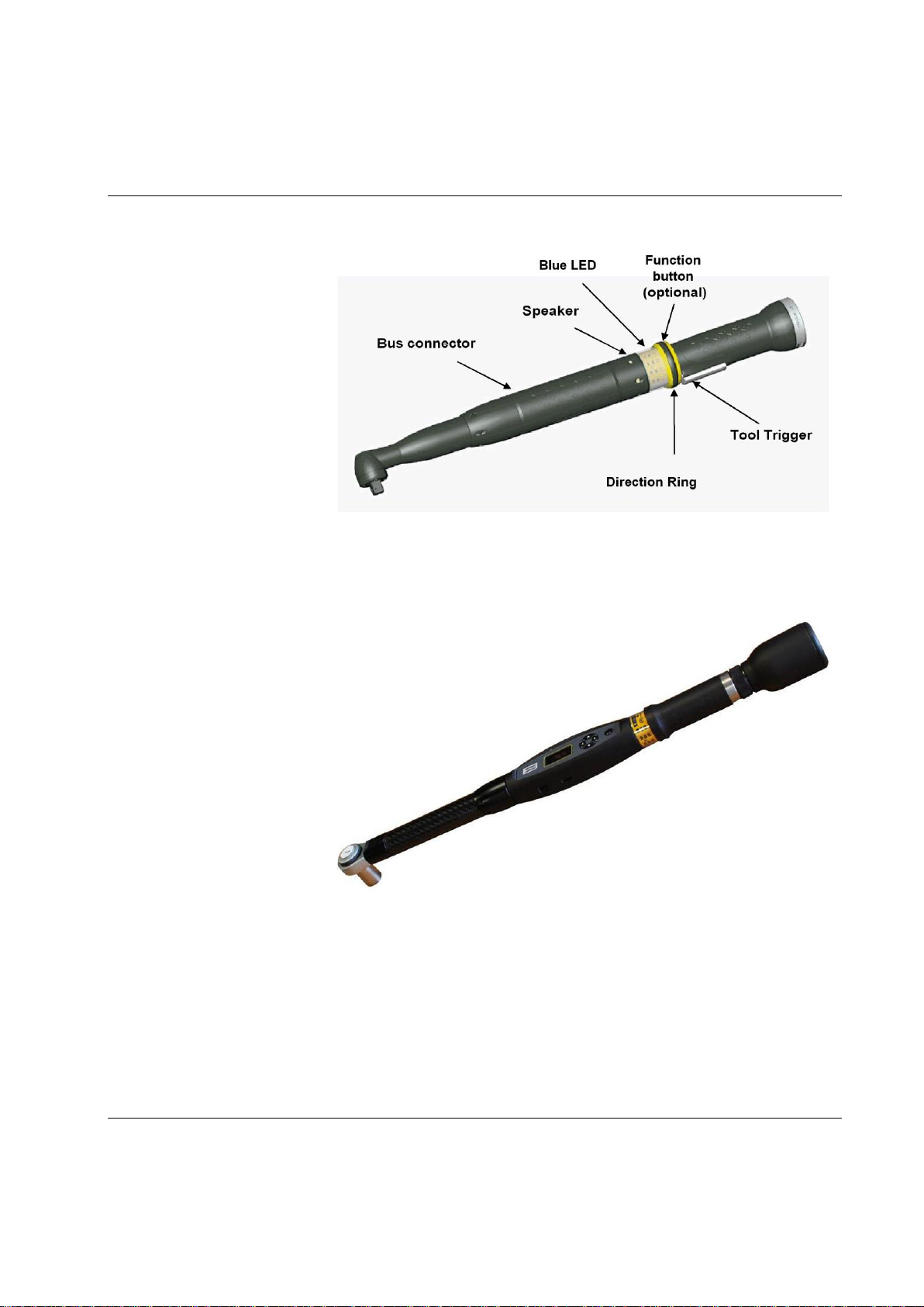
An open-end tool (or tube nut tool) is a
Tensor tool equipped with an openended head. It is used to tighten nuts
on tubes and similar applications. The
open-end is available for several, but
not all, tools.
Open-end tools can only be
used with lock-off lever for
personal safety reasons.
3.6 Tensor tools
This is a brief overview of Atlas Copco Tensor tools and tool accessories. See tool specific information for
a complete list of tools and options for each tool.
22 (428) 9836 3123 01
Introduction to Power Focus
Tool parts
Figure shows Tensor ST.
STwrench is a torque wrench
that can be controlled by the
Power Focus. The STwrench
communicates with the
tightening controller systems
through wireless digital
communication, built on IRC
(Industrial Radio
Communication) technique.
3.6.1 Tool accessories
See Atlas Copco tool specific information for a list of options for each tool.
9836 3123 01 23 (428)

Introduction to Power Focus
ST scanner is placed on the tool and works as a barcode reader. For more information
about the function of identifiers, see section Identifier.
GPIO (General purpose I/O) is a digital input and output connector. The four buttons
combined with four LED’s can each be configured as a digital input and/or digital
output.
ST selector has two different modes, mode 1 and mode 2. In Mode 1, the selector only
utilizes the tool accessory bus as GPIO. This mode only supports a maximum of 15 Psets
(1-15). In Mode 2, the selector takes full advantage of the bus capabilities.
For more information about the ST selector, see section ST-selector connection.
TLS ST Tag is an external positioning unit for positioning of the tool in the surroundings.
The unit also has a 7-color LCD indicator for sending status messages to the operator.
24 (428) 9836 3123 01
Introduction to Power Focus
The Power Focus concept features a number of accessories that simplify the guidance and follow-up of
performed tightenings. The accessory functions can be set up using ToolsTalk PF or a PF Graph unit.
The benefit of using serial bus-based accessories (I/O bus) is that they can be connected in series, from
accessory to accessory rather than hard wiring each accessory to the Power Focus. This arrangement
increases flexibility and quick installation.
Power Focus uses 24 V DC, 1 A to power the bus, which is also used to power external I/O's. If more
current is needed, the bus must be powered externally. Every device has a 24 V DC input for this
purpose.
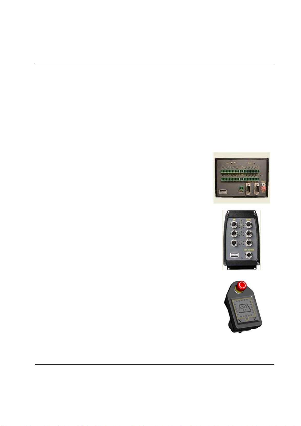
I/O Expander enables the connection of several inputs and relays when more
than those built-in are required. There are 8 inputs and 8 relays with the same
functionality as the four built-in I/O's. Each input and relay can be configured
individually.
I/O Expander, sealed
The sealed I/O Expander is designed for more demanding environments than
I/O Expander. It will add eight digital inputs as well as four digital and four
relay outputs to your system.
Indicator Box is a flexible display indicator used together with our Start
handle for indication of status signals from the controller. The box can easily
be connected to the Power Focus with premade cablings.
3.7 Hardware accessories
9836 3123 01 25 (428)
Introduction to Power Focus
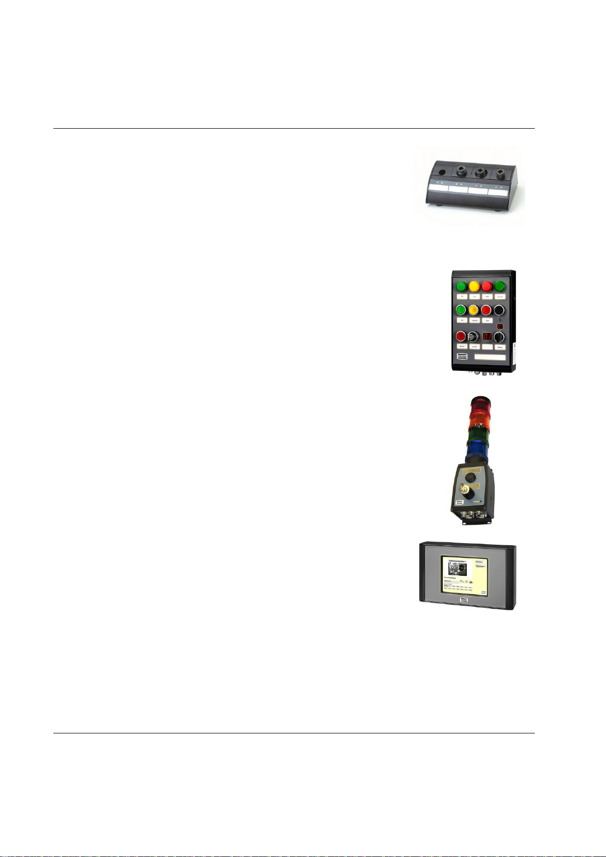
Socket Selector is a socket tray with LED’s that can be used to guide the user
through, for example, a Job sequence. When using more than one Pset it is
very convenient to use a selector. When a socket is lifted, the corresponding
Pset will be selected.
The Socket Selector is available with four or eight sockets, and
communicates on the I/O bus.
Operator Panel is an external device for PF. It is a general purpose lamp- and
switchbox, replacing the customer specials that are made today. The Operator Panel
communicates directly with Power Focus and the device configuration is made in
ToolsTalk PF.
Stacklight ESL-04 is a flexible light and switch device designed to interface with
controllers equipped with an I/O Bus.
Stacklight DSL-03 is a simple and customizable light and switch device, designed to
interface with controllers equipped with Internal I/O connectors instead of I/O-bus.
The stacklight comes with features such as buzzer, rotating light etc.
MiniDisplay is a compact remote interface. It runs the Operator Guidance
application program to give the operator visual support. It is equipped with a
touch-screen and is fully configurable. The MiniDisplay is connected through
Ethernet and does not support I/O-bus communication.
26 (428) 9836 3123 01

Introduction to Power Focus
ToolsNet works together with the controllers and the selected database, MS SQL Server or Oracle to
collect, store and visualize all historic tightening-related data. ToolsNet allows the user to get reports on
shifts, lines, individual vehicles or controllers for process improvement purposes. All the reports can
easily be exported to Excel.
ToolsNet can be used as a standalone product or together with the other modules from the ATS.
Factory Overview is the portal to the tightening process. It visualizes the whole process and makes it
possible to monitor all tightening applications from one central place. Factory Overview can be used both
as a standalone product and together with the other modules from the ATS.
Event Monitor offers real-time event reporting from the controllers in a centralized and filtered format.
Event Monitor can be used both as a standalone product and together with the other modules
from the ATS.
3.8 Software accessories
3.8.1 ATS
The ATS (Assembly Tools Software) works together with PF to complete the tightening process. The
following software products are part of ATS.
ToolsNet
Factory Overview
Event Monitor
Open Protocol
The PF open protocol can be run using Ethernet or serial communication. It is a full duplex protocol,
which means that data can be exchanged in both directions simultaneously. Every communication partner
must be able to operate a send and receive facility simultaneously.
The torque controller is the server and the station computer the client. The torque controller can accept up
to 5 connections at a time. The protocol used is TCP/IP.
9836 3123 01 27 (428)

Introduction to Power Focus
An ACTA 4000 performs a full range of functions, from simple torque checks
to advanced graphic tightening analysis. It comes in different models and it is
easy to upgrade.
ACTA 4000 measures torque, angle, and pulses and facilitates the conduction
of statistical analyses of the tightening process. An ACTA 4000, together
with the ToolsTalk QAT PC utility, is a complete SPC tool.
3.8.2 ACTA 4000
28 (428) 9836 3123 01
Connecting devices
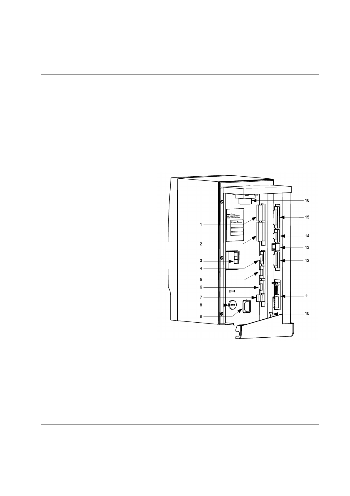
Backplane connections
1
Digital input + internal 24 V DC
2
Relays
3
Ground Fault Interrupter (GFI)
4
Serial #1 (RS 232) to MC-card
5
I/O Bus #1
6
I/O Bus #2
7
Remote start
8
Main fuse
9
Main fuse power connector
10
Ground connection
11
Fieldbus card (optional)
12
RBU
13
Ethernet
14
Serial #2 (RS232) to CC-card
15
Printer
16
Tool output
In addition to backplane connections,
PF4000 has a USB connection on the
front underside.
4 Connecting devices
This section describes the connections on PF backplane. It also describes the start-up process for PF and
for the tools.
4.1 PF connections
9836 3123 01 29 (428)

Connecting devices
Make sure that the power is switched off when connecting and disconnecting the RBU.
Cell network connection requires PF units with identical RBU types inserted.
The RBU serial number is also part of the Power Focus Ethernet MAC address.
When changing RBU type it is only possible to load the configuration from the RBU.
4.2 RBU
Connect the RBU to the 15-pin connector on the back panel of the Power Focus (see figure below).
The RBU unlocks the software and works as a backup memory for the Power Focus setup data.
The pin configuration is propriety information for Atlas Copco. This connector cannot be used for other
purposes.
Connector: 15-pin D-sub female.
Function: For connection of Atlas Copco RBU.
4.2.1 MAC-address
Power Focus Ethernet address is 00-50-D6 -XX-YY-ZZ (from serial RBU).
Example: RBU with serial number C00015767:
00015767 (decimal) → 003D97 (hexadecimal)
003D97 (hexadecimal) → 00-50-D6-00-3D-97 (MAC address)
4.2.2 PF start-up instructions
At start-up, the Power Focus checks for differences between the controller and RBU configurations. If an
inconsistency is detected the user is prompted to select either the controller or RBU configuration. This
makes it possible to move/copy configurations between PF units by using the RBU. The user is also given
the possibility to clear both configurations.
Press the plus (+) or minus (-) key on PF Compact front panel to toggle between the selections. Confirm
selection with the enter key. Press the corresponding soft key to make a selection on PF Graph.
The table describes the selections available and how to choose configuration. If the Power Focus and RBU
are incompatible for other reasons than a configuration mismatch (e.g. they have an older software
version), either PF or the RBU is considered as NOK.
30 (428) 9836 3123 01
 Loading...