

Atlas Copco PN 3500, PN 3500 X Repair Instructions
1
PAGE
Repair Instructions No.179.11/97
PN 3500 / PN 3500 X
Special Tools
Required
■
Forcing disks 4931 599 021
■
Special pliers 4931 599 057
■
(Dis-) Assembly tool 4931 5990 84
■
Sleeve 4931 599 038
■
Screw locking device Omnifit 80 4931 945 651
Important!
■
Before beginning the maintenance work, perform an initial check with a high voltage test according
to VDE (see chapter Electrical and Mechanical Test Instructions).
■
Before all repair work, pull the power plug from the socket!
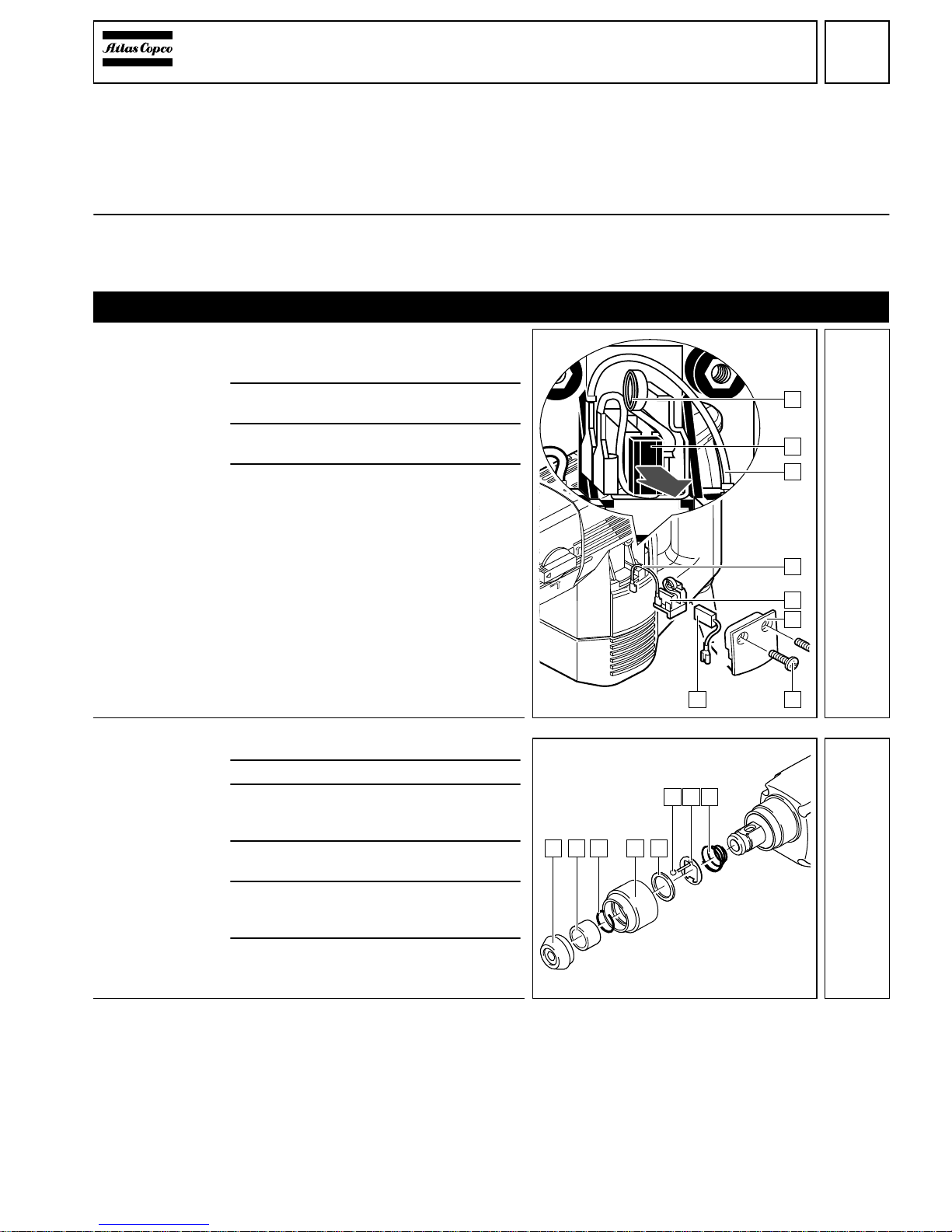
Disassembly
Removing the
carbon brushes
1
Loosen the two screws (6) on both sides
and remove the respective service covers (5).
2
Remove the cables (3) and pull the brush
holders (4) from the housing.
3
Put the springs (1) aside (see illustration)
and pull out the carbon brushes (2).
4
Pull the carbon brush cables together with
the carbon brushes (2) from the housing.
Only applicable
for PN 3500:
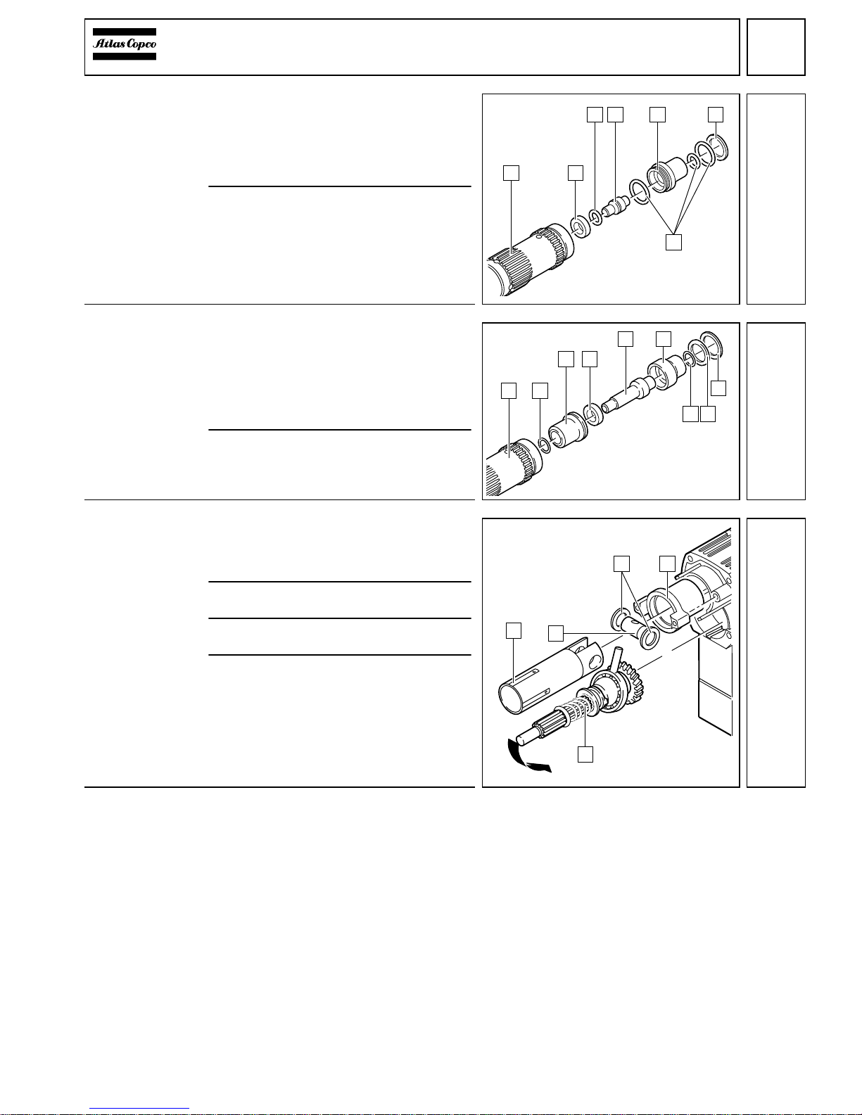
Dismantling the
SDS-Plus-reception
1
Remove the rubber cap (1).
2
Remove the spacer (2).
3
Depress the sliding sleeve (4) and lever
off the locking ring (3) with aid of a screwdriver.
4
Remove the sliding sleeve (4) and the retaining ring (5).
5
Depress the retaining disk (7) and press
out the ball (6) with aid of a screwdriver or
remove it with a magnet.
6
Remove the retaining disk (7) and the
spring (8).
1
2
3
4
5
6
3
2
1
1 2 3 5
6 7 8
4
2
2
PAGE
Repair Instructions No.179.11/97
PN 3500 / PN 3500 X
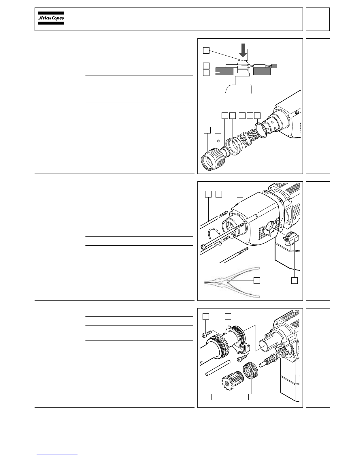
Only applicable
for PN 3500 X:
Dismantling the
FIXTEC-reception
1
Removing the locking sleeve (2):
☞
Fix the locking sleeve (2) in a pullingoff device (3) and press it out. At the
same time, press down the spindle (1)
with a suitable sleeve.
2
To remove the balls (4) (six pieces):
☞
Depress the seal ring (6) and remove
the balls with aid of a magnet.
3
Remove the remaining parts:
- seal ring (6)
- outer spring (7)
- ejector ring (5)
- inner spring (8) and
- washer (9).
Detaching the
gear housing
1
Switch the lever (4) to the "0"-position and
break it off with aid of pliers. The lever (4)
gets destroyed.
☞
Should this not be possible, fix the lever (4) in a vice and break it off by moving the machine to and fro. Remove
any broken part from inside the machine.
2
Remove the four housing screws (1).
3
Only applicable for PHE 3500 X:
Open the locking ring (2) on the spindle
with aid of special pliers (5) (service tool)
and remove it together with the gear housing (3).
Removing the
spindle
1
Remove the two screws (1).
2
Remove the straight pin (5).
3
Remove the planetary gear (4) and the
ring gear (3).
4
Remove the complete spindle sleeve (2)
from the cylinder.
1
2
3
5 6 7 8 9
42
2
1 3
5
2
4
3
1 2
5 4 3
4
3
PAGE
Repair Instructions No.179.11/97
PN 3500 / PN 3500 X
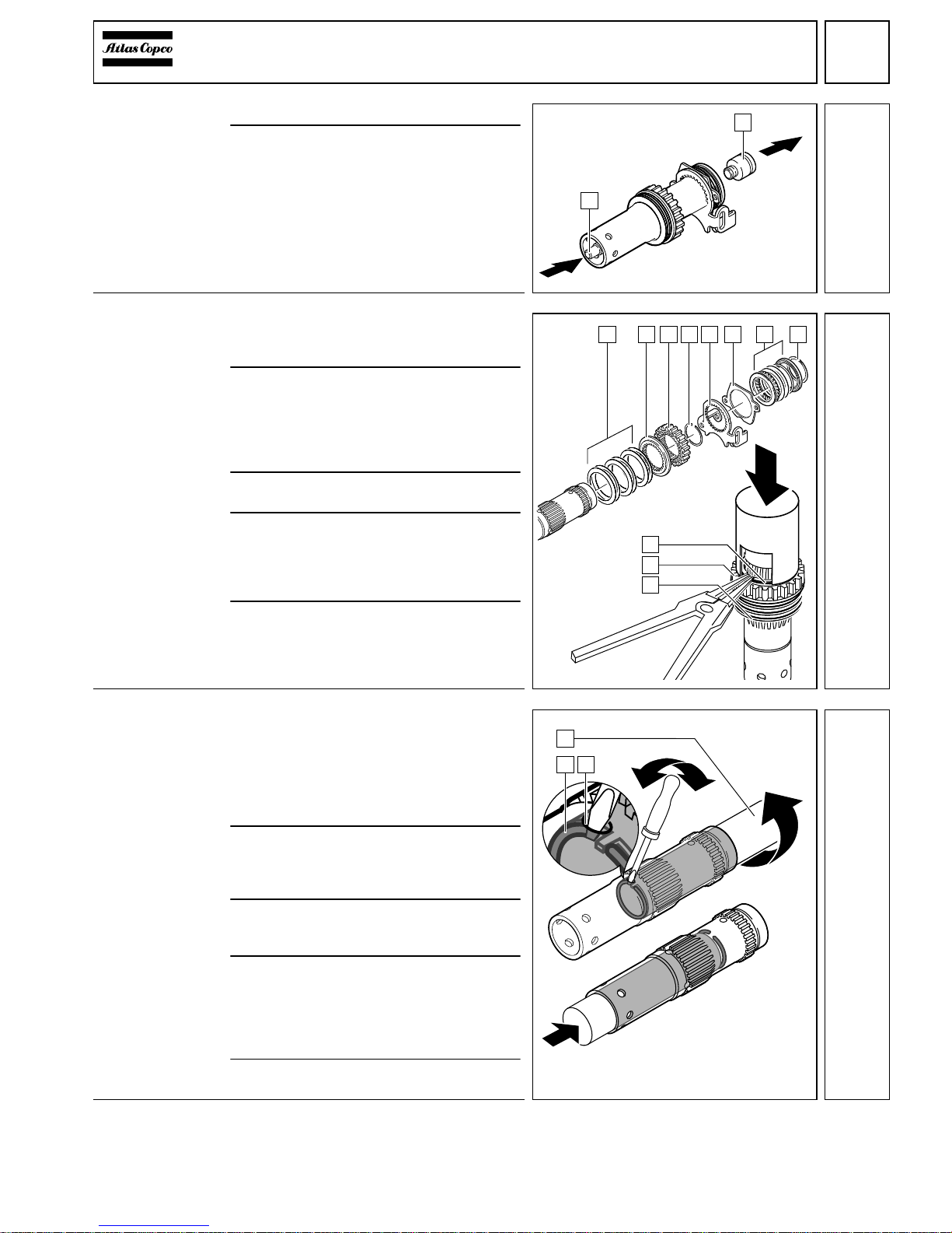
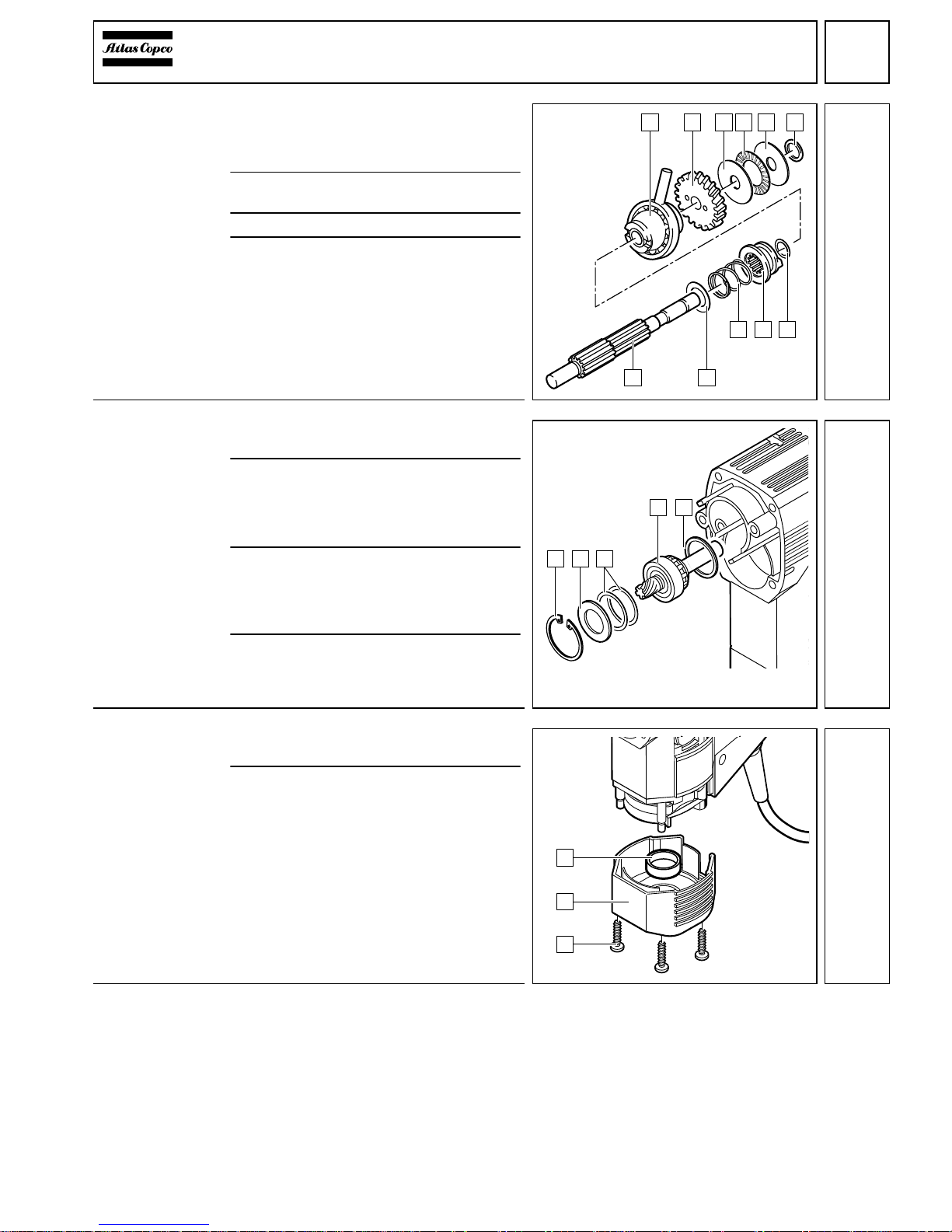
Removing the
striker
1
Place the spindle vertically.
2
Briefly hit the plunger (1) with a mandrel.
The striker (2) comes free.
Dismantling the
spindle (removing the outer
parts)
1
Removing the rear thrust bearing (7):
Lever off the special locking ring (8) with
aid of a screwdriver.
2
The thrust bearing can be removed in the
following component parts:
- washer
- thrust bearing washer
- two compensating washers and
- profile ring with damper O-ring.
3
Remove the retaining disk (6) and the
locking slide (5).
4
Removing the spindle wheel (3):
Press the spindle wheel (3) with a sleeve
against the disk springs (1) - the locking
ring (4) is released and can be removed
with pliers. Remove the spindle wheel (3).
5
Remove the ratchet (2) and the disk
springs (1).
Dismantling the
spindle (removing the inner
locking ring)
1
☞
In the middle of the spindle (1) there
are four deairing holes and one service
boring (3).
The service boring (3) has the smallest
diameter.
2
Turn the round wire locking ring (2) with
aid of the service tool (4931 599 084)
such that one end projects the service boring (3) by approx. 2 mm.
3
Put a screwdriver through the service
boring (3) and place it under the locking
ring (2).
4
Move the screwdriver to and fro and at the
same time turn the locking ring (2) with aid
of the service tool in direction of arrow.
☞
Turn the locking ring (2) until it is completely levered off the groove.
5
Press the locking ring (2) from the spindle.
1
2
5
1 72 3 5 6 84
1
3
4
6
1
2 3
7
4
PAGE
Repair Instructions No.179.11/97
PN 3500 / PN 3500 X
Only applicable
for PN 3500:
Dismantling the
spindle (removing the inner
parts)
1
Press the following parts from the
spindle (1):
- washer (6)
- pressure sleeve (5)
- plunger (4) and
- brake disk (2).
2
Remove the O-rings (3) and (7).
Only applicable
for PN 3500 X:
Dismantling the
spindle (removing the inner
parts)
1
Press the following parts from the
spindle (1):
- washer (9)
- pressure sleeve (6)
- plunger (5)
- brake disk (4) and
- pressure sleeve (3).
2
Remove the O-rings (2), (7) and (8).
Removing the
back gear shaft
and the cylinder
1
Pull out the bearing housing (4).
If necessary, loosen the bearing housing (4) by hitting the gear housing lightly
with a plastic hammer.
2
Remove the back gear shaft (5) by turning
or canting it (see arrow in illustration).
3
Completely remove the cylinder (1) and
the back gear.
4
Push out the bolt (2) by hand and remove
the two disks (3).
1 2
3 5 6
7
4
8
1 2
3
5 6
7 8
9
4
8
1
2
3
5
4
9
5
PAGE
Repair Instructions No.179.11/97
PN 3500 / PN 3500 X
Dismantling the
back gear shaft
1
Remove the rubber O-ring (6).
☞
Attention! The rubber O-ring (6) fits
tightly and is difficult to remove.
2
Remove the washer (5) and the thrust
bearing (4) as well as the disk (3).
3
Press off the back gear wheel (2).
4
Remove the remaining parts from the
back gear shaft (B):
- tumble drive (1)
- washer (7)
- coupling box (8)
- spring (9) and
- washer (A).
Removing the
angle drive
1 Remove the locking ring (1) with aid of
special pliers.
2 Remove the angle drive (4) together with
the disk (2), the washers (3) as well as the
support ring (5).
If necessary, hit the gear housing lightly
with a plastic hammer for support.
3
☞
Depending on the tolerance of the
bearing the tool can be equipped with
two or three washers (3).
4 If this bevel wheel will be used again,
please note the number of the washers.
Mount the same number when re-assembling.
Removing the
motor cover
1 Loosen the four screws (1) and remove
the motor cover (2).
2 Remove the rubber cap (3) in case of
damage.
B A
9 7
1 2 3 54 6
8
10
1 3
4 5
2
11
3
2
1
 Loading...