

Atlas Copco Pionjar 120, Pionjar 150, Pionjar 130, Pionjar 140 Operator Instructions Manual
Operator’s Instructions
Instructions pour l’opérateur
Bedienungsanleitung
Instrucciones para el operario
Instruções de operação
Istruzioni per l’uso
Bedieningsinstrukties
Odhgíew gia ton xeiristq
Käyttöohje
Betjeningsvejledning
Bruksanvisning
Skötselinstruktion
Motor drills
Marteaux perforateurs
Motorbohrhämmer
Motoperforadoras
Martelo perfurador
Perforatrici a motore
Motorboorhamers
Benzinokínhtew Wfúrew
Moottoriporakoneet
Motorborehamre
Motorboremaskiner
Motorborrmaskiner
120
13 0
14 0
150
AIB
1996-12
© Copyright 1996, ATLAS COPCO BEREMA AB No 9852 0878 90b
STOCKHOLM • SWEDEN
H
A
A
G
B
C
I
J
D
K
E
L
F
M
N
Fig. 1b
AI: 5%
Fe: 8%
O
P
Fig. 1a
Fig. 3
Fig. 2
Fig. 4a
Fig. 4b
2
Fig. 5a
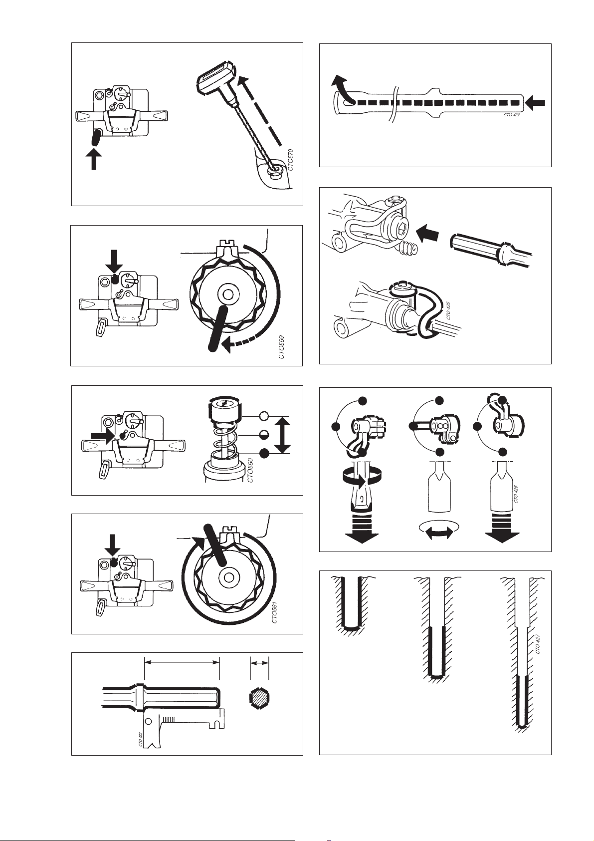
Fig. 5b
Fig. 8
Fig. 5c
Fig. 6a
Fig. 6b
Fig. 9
Fig. 10
Fig. 7
Fig. 11
3

English
Safety regulations
These instructions contain important sections dealing with safety.
Specialattentionmust be paid to all framed safetytextthatbegins with a warning symbol (triangle)followedby
a signal word, as shown below.
denotes a hazard or hazardous procedure which CAN lead to serious or
! WARNING
! CAUTION
Also observe the following general safety rules:
life-threatening injuries if the warning is not observed.
denotes a risk or risky procedure which CAN lead to personal injury or
damage to equipment if the warning is not observed.
Before starting the machine, read through
q
these instructions carefully.
Also read through the red safety instruc-
q
tions before putting the machine to use.
For reasons of product safety, the machine
q
must not be modified.
Data
Pionjär 120.......................Combined rock-drill and breaker
Pionjär 140.......................Combined rock-drill and breaker
Pionjär 130.......................Breaker only
Pionjär 150.......................Breaker only
Engine
Type.................................1-cylinder, two-stroke, air cooled
Cylinder displacement .....185 cc
Crankshaft speed.............2550-2650 rev/min (blows/min)
Carburettor.......................Floatless, with manual needle valve
Ignition system.................Thyristor type, breakerless
Spark plug
(recommended) ...............Motorcraft AE-6, Bosch W7AC
Spark plug gap.................1.5 mm
Starter..............................Magnapull
Fuel type..........................Petrol, 90–100 octane, leaded
Oil type.............................Atlas Copco two-stroke oil or a
Fuel mixture.....................Cast-iron cylinder 8%, 1:12
Tank volume.....................1.5 l
Fuel consumption ............1.3-1.5 l/h
Capacities, Pionjär 120, Pionjär 140
Max. drilling depth............6 m
Penetration rate ...............300-350 mm/min with 29 mm bit
.........................................250-300 mm/min with 34 mm bit
.........................................150-200 mm/min with 40 mm bit
Drill rotation speed...........250 rev/min
(loaded machine on concrete chisel)
or unleaded
recommended two-stroke oil
Aluminium cylinder 5%, 1:20
Use approved personal protective equip-
q
ment.
Use Atlas Copco Genuine Parts only.
q
Always replace worn or damaged signs.
q
Other data
Tool shank..............22x108 mm
Weight Length Width
Pionjär 120.............27 kg.............730 mm.........330 mm
Pionjär 130.............25 kg.............700 mm.........330 mm
Pionjär 140.............25 kg.............760 mm.........390 mm
Pionjär 150.............23 kg.............730 mm.........390 mm
Connection of grinding machine - please see separate instructions.
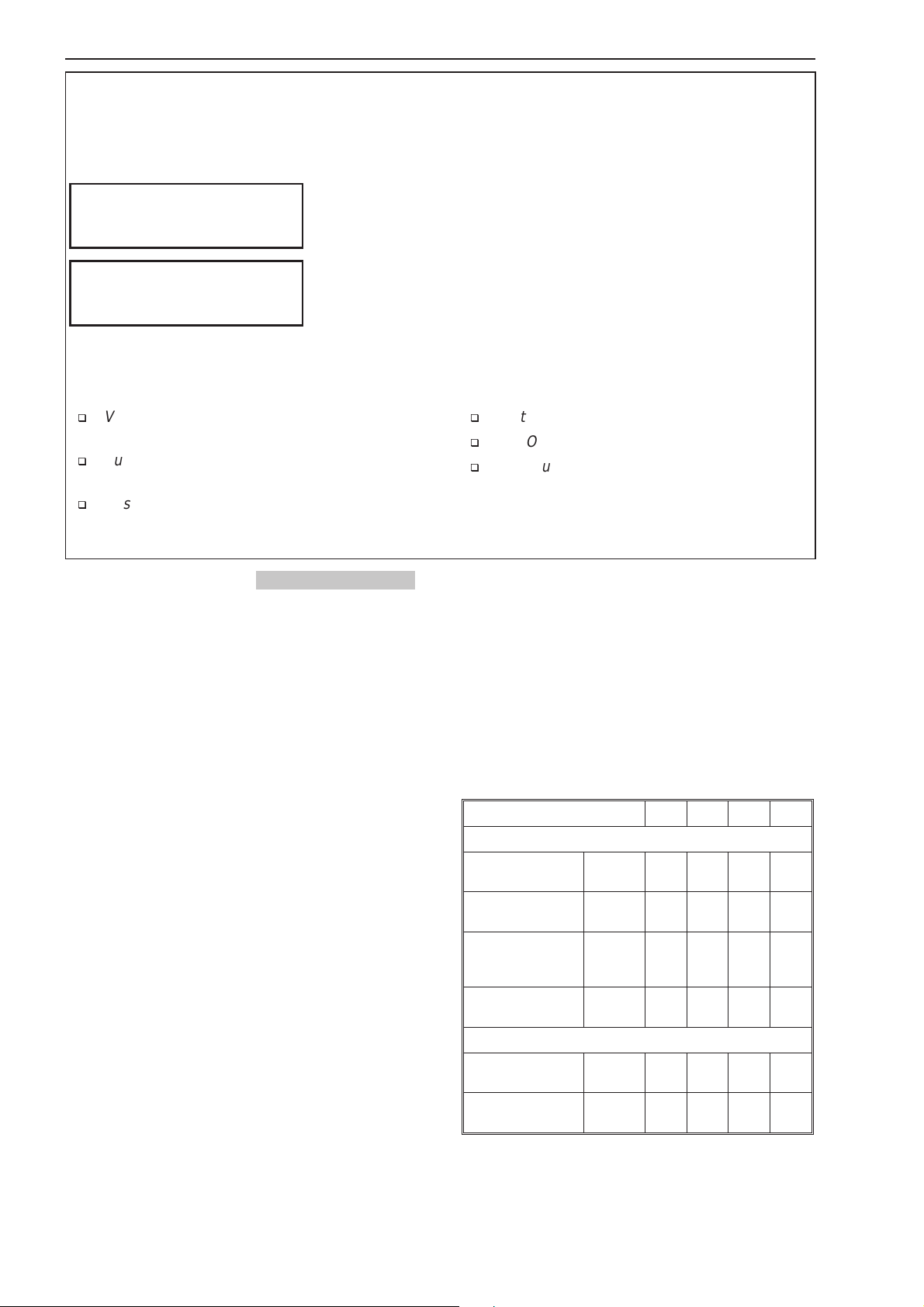
Declaration of noise and vibration emission
Pionjär models 120 130 140 150
Noise according to PN8NTC2
Measured sound
pressure level
Spread in method
and production
Measured sound
power level
Spread in method
and production
Vibration according to EN28662
Measured vibration
value
Spread in method
and production
p dB(A) 98 98 99 99
)
kp dB(A
w dB(A) 112 112 113 114
kw dB(A
a m/s
ka m/s
4.0 4.0 4.0 4.0
)
4.0 4.0 4.0 4.0
2
20 19 4.5 6.0
2
5.0 5.0 3.0 3.0
4

English
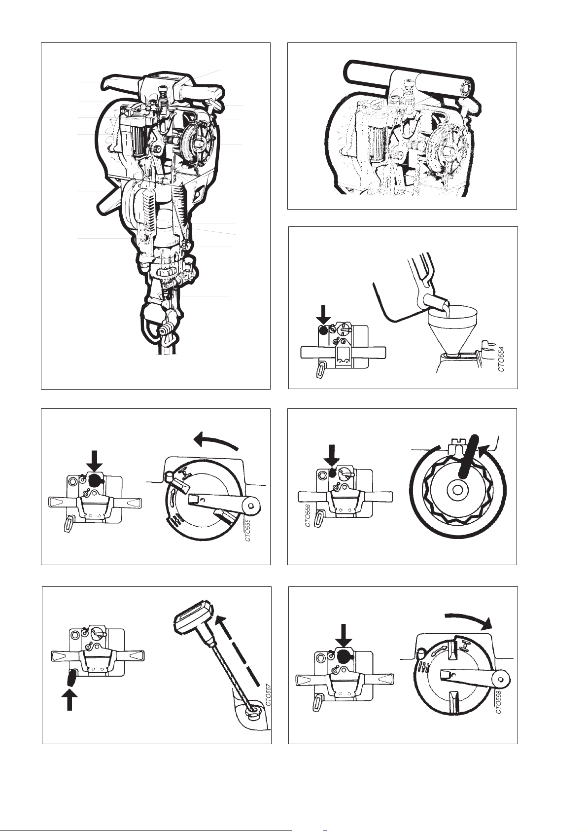
Main parts
Pionjär 140 (fig. 1a) Pionjär 120 (fig. 1b)
A. Handle (vibration damped on Pionjär 140/150)
B. Fuel screw
C. Choke
D. Air filter
E. Engine piston
F. Compression chamber for flushing air
G. Rotation mechanism (Pionjär 120 and 140)
H. Throttle
I. Starter handle
J. Fuel tank
K. Power take-off
L. Gas duct
M. Impact piston
N. Gas-duct valve
O. Function selector (Pionjär 120 and 140)
P. Tool holder
If the engine does not start, too much fuel may have
entered the combustion chamber.In this case, close
the fuel needle by turning it clockwise, and start the
engine with the choke open.
The engine speed can be regulated by means of the
throttle (fig. 6a). When the throttle is released to the
“up” position, the maximum engine speed is obtained. Depressing the throttle halfway down gives the
engineidlingspeed.To stoptheengine,simplypress
the throttle to the bottom position.
If the machine is frequently started on top of long
toolssuchas probing rods etc; a starter-cord bracket
must be used to avoid damaging the cord and cord
bushing.
Starter-cord bracket for Pionjär 120, 130, 140,
150: Ordering No. 9238 2803 81.
Stopping the machine (figs. 6a and 6b)
To stop the engine, press the throttle all the way
down to the bottom position (fig. 6a). Then close the
fuel needle by turning it clockwise (fig. 6b).
N.B. Drain the fuel tank if the machine is to be transported or stored for longer periods of time.
Starting and stopping the
Machine
Fuel mixing ratios (fig. 2)
Pionjär with cast-iron cylinder: oil-mixed petrol, 1
part oil to 12 parts petrol (8%).
Pionjär with aluminium cylinder: oil-mixed petrol, 1
part oil to 20 parts petrol (5%).
Two-stroke oil
Forthe best resultsalways use AtlasCopco’sbiodegradable two-stroke oil, wich has been specially developed for Atlas Copco two-stroke engines. If Atlas
Copco two-stroke oil is not available then use a twostroke oil of good quality.Contact your nearest Atlas
Copco dealer for a recommendation of two-stroke
oils.
Starting (figs. 3-6a)
When cold-starting the engine, turn the choke anticlockwise (fig. 3).
Turn up the fuel needle (anti-clockwise) toward the
stop(fig. 4a). Pull thestarting handle until theengine
starts (fig. 4b).
Open the choke fully by turning it fully clockwise
(fig. 5a).
After starting the engine (fig. 5b), let it warm up for
2-3 minutes before putting the machine to work.
Regulate the fuel supply so that the engine runs
cleanly. During normal operation the fuel needle
should be opened by approx. 0.5 of a turn (fig. 5c).
Operating the machine (fig. 7)
Tool shank (fig. 7)
Use a shank gauge to check that the tool shank has
the correct dimensions, i.e. 22x108 mm. Make sure
that the shank is clean and that the tool is in good
condition.
Flushing (fig. 8)
During drilling, make sure that the flushing hole
through the drill steel does not become blocked.
Fitting the tool (fig. 9)
Shutdownthemachine.Insertthe tool shank into the
chuck and lock the tool retainer with your foot.
Function selector - Drilling (fig. 10)
Turn the function selector downward. This engages
rotation and flushing air for drilling.
Function selector - Breaking (fig. 10)
To adjust the direction of the tool blade, first put the
function selector into the neutral position.
Then lock the tool in the desired position by turning
the selector upward. This locks the rotation.
Collaring
Press the tool against the workpiece with the machine idling. Increase the speed of the engine once
the bit has gained a foothold in the material to be
drilled.
Grip the side handle to give better control of the machine.
5

English
Drilling deep holes (fig. 11)
First drill a short drill steel all the way into the hole.
Then change to a longer drill steel with a slightly
smaller bit diameter (approx. 1 mm smaller).
Regular service
Air filter (fig. 12)
Cleanthe air filter regularly,at least once a shiftif the
machine is in continuous use.
Turn the locking spring of the filter housing to the
side,and take out thefilter housing and filter.Tap the
filter carefully with the palm of your hand, or blow
through it carefully with compressed air.
N.B. Blow from the inside out.
If the filter is very dirty, it should be replaced.
Paper filters must never be washed.
Gas duct (fig. 13)
Thegasductmustbecheckedregularlyand cleaned
of carbon deposits.
Pull the starter handle slowly until the arrow at the
centre of the flywheel points upward (which means
thattheenginepistonis at its upper turning position).
Unscrew the gas-duct valve and take out the cleaning rod. Use the accompanying cleaning needle to
clean both the duct and the cleaning rod.
Checkthattheball inthegas-ductvalveisnot stuck.
Maintenance
Spark plug (fig. 14)
Remove the spark-plug cap and then remove the
spark plug with the aid of a plug spanner.
If the spark plug is dirty or burned, it should be replaced. Use an original spark plug type Motorcraft
AE6 or Bosch W7A.
If the spark plug is wet with fuel, dry it with a clean
clothandcheckthespark.Thenpullthestartinghandle 2-3 times to get rid of any excess fuel.
Fit the spark plug back into the cylinder.
The electrode gap should be 1.5 mm.
Changing the starter cord (figs. 15a15d)
Remove the protective cover of the starter mechanism, at the same time grasping the starter pulley so
thatitcomesoffwith the cover.Carefullyletthecover
rotateinorder to release the spring tension. Remove
the old starter cord.
Fit the new starter cord.
Check the gasket between the fuel tank cover and
the protective cover. Oil the starter pulley’s needle
bearing.Fit together the starter pulley and protective
cover,with the starter spring fixed into the starter pulley. Wind all of the cord on to the starter pulley.
Pre-tension the starter spring by turning the pulley
clockwise by approx. 360° relative to the cover before mounting the assembly. Pull the starter handle
carefullyinorderto locate the cover correctly.Fitand
tighten the nuts for the protective cover.
Chuck bushing (fig. 16)
I the chuck gauge provided can be inserted all the
way into the chuck bushing (i.e. between the flats of
the bushing), this indicates that the bushing is worn
out and must be replaced.
Fault finding
If the machine does not start, is difficult to start, runs
unevenly or has low power output, check the figures
2 - 16.
If, after checking the figures, the machine still does
not function satisfactorily, please contact your nearest Pionjär workshop.
Anyunathorizeduse or copyingof the contentsorany part thereof
is prohibited. This applies in particular to trademarks, model denominations, part numbers and drawings.
6

Français
Prescriptions de sécurité
Les présentes instructions comportent des consignes de sécurité importantes.
Accorderune attention particulière àtouteinformation encadrée précédée d’unsymbole (triangle) et d’unmot
d’alerte qui signifient ce qui suit:
signale un risque ou une procédure présentant un risque qui PEUT EN-
! ATTENTION
! PRUDENCE
Considérer également les consignes de sécurité suivantes :
TRAINERunaccidentcorporelgraveou la mort si les consignes de sécurité ne sont pas suivies.
signale un risque ou une procédure présentant un risque qui PEUT ENTRAINERun accident corporel ou undommagematériel si les consignes
de sécurité ne sont pas suivies.
Avant la mise en marche, lire soigneusement
q
les présentes instructions.
Avant la mise en marche, lire également les
q
prescriptions de sécurité séparées (imprimé rouge).
Ne pas modifier la machine pour des raisons
q
de sécurité du produit.
Caractéristiques techniques
Pionjär 120.......................Marteau perforateur et piqueur com-
biné
Pionjär 140.......................Marteau perforateur et piqueur com-
biné
Pionjär 130.......................Marteau piqueur
Pionjär 150.......................Marteau piqueur
Moteur
Type.......................................Deux temps monocylindre
Cylindrée................................185 cm3
Régime du vilebrequin ...........2550 -2650 tr/min (coups/min)
Carburateur............................Sans flotteur avec soupape à
Système d’allumage...............Thyristorisé, sans rupteur
Bougie recommandée............Motorcraft AE-6, Bosch W7A C
Ecartement des électrode ......1,5 mm
Démarreur..............................Magnapull
Carburant...............................Essence, indice d’octane
Huile.......................................Huile 2 temps Atlas Copco
Mélange de carburant ............Cylindre en fonte 8 %, 1:12
Capacité du réser...voir..........1,5 l
Consommation de carburant .1,3 -1,5 l/h
Capacité, Pionjär 120 et 140
Profondeur maxi de
forage...............................6 m
Vitesse de pénétration.....300-350 mm/min avec taillant 29 mm
.........................................250-300 mm/min avec taillant 34 mm
.........................................150-200 mm/min avec taillant 40 mm
Vitesse de rotation..........250 tr/min
refroidi par air
(machine chargée avec burin
à béton)
pointeau manuelle
90-100 octanes, avec ou
sans plomb
ou marque recommandée
Cylindre en aluminium 5 %, 1:20
Utiliser l’équipement de sécurité approuvé.
q
N’utiliser que les pièces d’origine Atlas
q
Copco.
Remplacer les plaques indicatrices endom-
q
magées ou usées.
Autres caractéristiques
Emmanchement d’outil.................22x108 mm
Poids Longueur Largeur
Pionjär 120.............27 kg.............730 mm.........330 mm
Pionjär 130.............25 kg.............700 mm.........330 mm
Pionjär 140.............25 kg.............760 mm.........390 mm
Pionjär 150.............23 kg.............730 mm.........390 mm
Accouplement d’une affûteuse - voir instructions
séparées.
Emissions de bruit et de vibrations
Modèles Pionjär 120 130 140 150
Bruit selon PN8NTC2
Niveau de pression
acoustique mesuré
Diffusion théorique
et en exploitation
Niveau de puissance acoustique
mesuré
Diffusion théorique
et en exploitation
Vibrations selon EN28662
Valeur de vibrations
mesurée
Propagation théorique et en exploitation
p dB(A) 98 98 99 99
)
kp dB(A
w dB(A) 112 112 113 114
kw dB(A
a m/s
ka m/s
4.0 4.0 4.0 4.0
)
4.0 4.0 4.0 4.0
2
20 19 4.5 6.0
2
5.0 5.0 3.0 3.0
7

Français
Eléments principaux
Pionjär 140 (fig. 1a) Pionjär 120 (fig. 1b)
A Poignées (antivibratiles sur Pionjär 140/150
B. Vis de dosage
C. Starter
D. Filtre à air
E. Piston moteur
F. Chambre de compression pour air de soufflage
G. Mécanisme de rotation (Pionjär 120/140)
H. Commande des gaz
I. Poignée de lancement
J. Réservoir de carburant
K. Prise de puissance
L. Conduit des gaz
M. Piston percuteur
N. Soupape du conduit des gaz
O. Sélecteur (Pionjär 120/140)
P. Etrier
Régler le régime avec la commande des gaz (fig.
6a). Position non enfoncée : plein régime, position
mi-enfoncée: ralenti et position complètement enfoncée : arrêt.
Si le démarrage se fait souvent avec un outil long
monté,parexempletiged’entraînement ou similaire,
ilestrecommandéd’utiliserunguidepournepasendommagerlacordeletteet lemanchondeprotection.
Guide pour Pionjär 120, 130, 140, 150 :
réf. 9238 2803 81.
Arrêt (fig. 6a et 6b)
Arrêter la machine en appuyant à fond sur la commande des gaz (fig. 6a).
Fermer la vis d’alimentation dans le sens horaire et
vider le réservoir dans le caséventuel d’un transport
et d’une longue interruption (fig. 6b).
Utilisation
Emmanchement d’outil (fig. 7)
Vérifier avec un calibre que les dimensions de l’emmanchement d’outil sont correctes : 22x108 mm.
L’emmanchement doit être propre et l’outil doit être
en bon état.
Marche-arrêt
Carburant (fig. 2)
Pionjär avec cylindre en fonte : rapport de mélange
huile-essence 1:12 (8 %). Pionjär avec cylindre en
aluminium : rapport de mélange huile-essence 1:20
(5 %).
Huile pour moteur deux temps
Pour assurer les performances de la machine, utiliser de l’huile biodégradable pour monteur deux Atlas Copco. Si cette huile spécialement développée
n’est pas disponible, choisir une huile pour moteur
deux temps de bonne qualité. Contacter votre concessionnaire Atlas Copco pour toute information
complé-mentaire.
Démarrage (fig. 3 - 6a)
Démarrage à froid : tourner le starter dans le sens
antihoraire (fig. 3).
Ouvrir à fond la vis d’alimentation dans le sens antihoraire (fig. 4a). Tirer la poignée de lancement
jusqu’à faire démarrer le moteur (fig. 4b).
Tourner à fond le starter dans le sens horaire (fig.
5a).
Démarrer et laisser réchauffer le moteur (fig. 5b)
pendant 2-3 minutes avant de commencer les travaux. Régler l’alimentation en carburant de sorte
quelemoteurtournerégulièrement. Dans des conditions d’utilisation normales, la vis d’alimentation doit
être ouverte d’environ 0,5 tour (fig. 5c).
Si le moteur ne démarre pas, il y a trop de carburant
dans la chambre de combustion.
Fermer la vis d’alimentation dans le sens horaire et
démarrer avec le starter ouvert.
Soufflage (fig. 8)
Enforage,vérifier que le conduit d’airdufleuret n’est
pas bouché.
Montage de l’outil (fig. 9)
Arrêterla machine. Introduire l’outil dansla douille et
le bloquer l’étrier avec le pied.
Sélecteur - forage (fig. 10)
Mettrelesélecteurenbas.Larotationetl’airdesoufflage sont mises en circuit.
Sélecteur - piquage (fig. 10)
Régler l’angle d’attaque de l’outil en commençant
par mettre le sélecteur au point neutre.
Bloquer ensuite l’outil dans la position souhaitée en
mettant le sélecteur en haut. La rotation est maintenant bloquée.
Amorçage
Appuyer l’outil contre l’objet à travailler avec le moteur tournant au ralenti. Augmenter le régime quand
l’outil a une prise satisfaisante.
Utiliserlapoignéelatéralepour mieux manoeuvrer la
machine.
Forage de trous longs (fig. 11)
Commencer avec un fleuret court et utiliser toute sa
longueur,puis le remplacer par un autre plus long et
d’un diamètre plus petit (environ 1 mm).
8

Français
Entretien régulier
Filtre à air (fig. 12)
Nettoyer régulièrement le filtre à air; en utilisation
continue, le nettoyer au moins une fois à chaque
nouvelle équipe de travail.
Ecarterleressortdeblocageduboîtierdefiltreetenlever le boîtier et le filtre. Frapper le filtre avec précautioncontrelapaumede la mainousoufflerdel’air
comprimé de l’intérieur.
Si le filtre est très encrassé, le remplacer.
Ne jamais laver le filtre en papier.
Conduit des gaz (fig. 13)
Vérifier régulièrement le conduit des gaz et éliminer
la calamine.
Tirer lentement la poignée de lancement jusqu’à ce
que la flèche au centre du volant magnétique pointe
verslehaut(lepistonmoteurse trouve alors au point
mortsupérieur). Dévisser la soupape du conduit des
gaz et enlever le fil de curage. Nettoyer le conduit et
le fil de curage avec l’aiguille-curette livrée.
Vérifierque la bille de lasoupapedu conduit des gaz
ne s’est pas coincée.
Douille (fig. 16)
S’il est possible d’introduire complètement le calibre
livré dans les interstices de la douille, celle-ci est
usée et doit être remplacée.
Recherche des pannes
Si le moteur ne démarre pas, démarre difficilement,
tourneirrégulièrement,ousisapuissance est insuffisante, vérifier ci-dessus fig. 2 - 16.
Si le marteau ne fonctionne toujours pas d’une
manière satisfaisante après ces mesures, contacter
l’atelier Pionjär le plus proche.
Entretien
Bougie (fig. 14)
Enleverlecapuchonet sortir labougieavecunecléà
bougie.
Si les électrodes sont encrassées ou brûlées, remplacer la bougie. Utiliser une bougied’origine Motorcraft AE6 ou Bosch W7AC.
Sila bougie est mouillée decarburant, l’essuyer.Vérifier l’étincelle et tirer 2 -3 fois la poignée de lancementpouréliminerle surpluséventueldecarburant.
Remonter la bougie dans le cylindre.
L’écartement d’électrodes doit être 1,5 mm.
Remplacement de la cordelette de
lancement (fig. 15a -15d)
Libérer le couvercle de protection du démarreur.
Soulever le couvercle et saisir la poulie de lancement pour qu’elle suive. Laisser lecouvercle tourner
avec précaution de sorte que la tension du ressort
s’annule. Dégager l’ancienne cordelette de lancement.
Monter la nouvelle cordelette.
Vérifier le joint entre le carter du réservoir et le cou-
vercle de protection. Huiler le roulement à aiguilles
de la poulie de lancement. Assembler la poulie et le
couvercle de sorte que le ressort de démarreur soit
bien fixé à la poulie. Enrouler toute la cordelette sur
la poulie.
Préarmer le ressort de démarreur d’environ 1 tour
dans le sens horaire avant de monter l’ensemble.
Tireren même temps avec précaution la poignée de
lancement pour que le couvercle vienne en place.
Serreràfondles écrousducouvercledeprotection.
Toute utilisation ou reproduction non autorisée du contenu, ou
d’une partie du contenu, est illicite. Cela s’applique particuliérement aux marques déposé, aux désignations de modèles, aux
numéros de pièces et aux plans.
9
Deutsch
Sicherheitsvorschriften
Diese Bedienungsanleitung enthält wichtige Sicherheitshinweise.
Die umrahmten, die Sicherheit betreffenden Textstellen, denen ein von einem Hinweiswort ergänztes Warn-
symbol (Dreieck) vorangeht, müssen besonders beachtet werden (siehe unten).
Deser Hinweis deutet auf Gefahren oder gefährliche Arbeiten, die bei
! WARNUNG
! ACHTUNG
Zusätzlich sind die nachstehenden allgemeinen
Nichtbeachtung der Warnung schwere oder lebensbedrohliche Verletzungen herbeiführen KÖNNEN
Dieser Hinweis deutet auf Gefahren oder gefährliche Arbeiten, die bei
Nichtbeachtung der Warnung Verletzungen oder Schäden am Gerät
verursachen KÖNNEN.
Sicherheitsvorschriften zu befolgen:
Vor Inbetriebnahme der Maschine diese An-
q
leitung sorgfältig durchlesen.
Zusätzlich die roten Sicherheitshinweise
q
vor Inbetriebnahme der Maschine lesen.
Aus Gründen der Produktsicherheit dürfen an
q
der Maschine keine Änderungen vorgenommen werden.
Technische Daten
Pionjär 120.......................Kombinierter Bohrhammer und
Pionjär 140.......................Kombinierter Bohrhammer und
Pionjär 130.......................Nur Aufbrechhammer
Pionjär 150.......................Nur Aufbrechhammer
Motor
Bauart..............................Einzylinder-Zweitaktmotor, luftgekühlt
Hubraum..........................185 cm3
Drehzahl, Kurbelwelle......2550 bis 2650 U/min (Schläge/min)
Vergaser ..........................Schwimmerlos mit manuellem
Zündung...........................Kontaktlose Thyristorzündung
Zündkerze........................Motorcraft AE-6, Bosch W7AC
Elektrodenabstand...........1,5 mm
Startapparat.....................Magnapull
Kraftstoff...........................Zweitakt-Gemisch
Mischungsverhältnis ........Gußeisenzylinder 8% (1:12)
Benzin..............................90 bis 100 Oktan, verbleit
Motorenöl.........................Atlas Copco Zweitaktöl oder
Tankinhalt.........................1,5 l
Kraftstoffverbrauch...........1,3 bis 1,5 l/h
Leistung, Pionjär 120, Pionjär 140
Max. Bohrlochtiefe...........6 m
Bohrgeschwindigkeit........300-350 mm/min mit 29-mm-Bohrer
.........................................250-300 mm/min mit 34-mm-Bohrer
.........................................150-200 mm/min mit 40-mm-Bohrer
Bohrdrehzahl ...................250 U/min
Aufbrechhammer
Aufbrechhammer
(belastete Maschine auf
Betonmeißel)
Nadelventil
Aluminiumzylinder 5% (1:20)
oder bleifrei
empfehlen Zweitaktöl
Stets zugelassene Schutzkleidung tragen.
q
Nur Originalteile von Atlas Copco verwenden.
q
Abgenutzte oder beschädigte Aufkleber stets
q
auswechseln.
Sonstige Daten
Werkzeugaufnahme .....................22 x 108 mm
Gewicht Länge Breite
Pionjär 120.............27 kg.............730 mm.........330 mm
Pionjär 130.............25 kg.............700 mm.........330 mm
Pionjär 140.............25 kg.............760 mm.........390 mm
Pionjär 150.............23 kg.............730 mm.........390 mm
Anschluß der Schleifmaschine - siehe separate
Anleitung.
AngabenzurGeräusch-und Vibrationsemission
Pionjär-Modelle 120 130 140 150
Geräusch gem. PN8NTC2
Gemessener
Schalldruckpegel
Streuung in Methode und Produktion
Gemessener
Schalleistungspegel
Streuung in Methode und Produktion
Vibration gem. EN28662
Gemessener
Vibrationspegel
Streuung in Methode und Produktion
p dB(A) 98 98 99 99
kp dB(A) 4.0 4.0 4.0 4.0
w dB(A) 112 112 113 114
kw dB(A) 4.0 4.0 4.0 4.0
2
a m/s
ka m/s
20 19 4.5 6.0
2
5.0 5.0 3.0 3.0
10

Deutsch
Hauptteile
Pionjär 140 (Bild 1a) Pionjär 120 (Bild
1b)
A. Handgriff (vibrationsschluckend bei Pionjär 140
und 150)
B. Kraftstoffschraube
C. Starterklappe
D. Luftfilter
E Motorkolben
F. Verdichtungskammer für Spülluft
G. Rotationsvorrichtung (Pionjär 120 und 140)
H. Gasknopf
I. Startergriff
J. Kraftstofftank
K. Zapfwelle (Abtrieb)
L. Gaskanal
M. Schlagkolben
N. Gaskanalventil
O. Funktionswähler (Pionjär 120 und 140)
P. Werkzeughalter
Anlassen-Abstellen
Kraftstoff (Bild 2)
Pionjär mit Gußeisenzylinder: Zweitaktgemisch, ein
Teil Öl auf 12 Teile Benzin (8%).
PionjärmitAluminiumzylinder:Zweitaktgemisch,ein
Teil Öl auf 20 Teile Benzin (5%).
Zweitaktöl
Für beste Resultate immer nur das für Atlas CopcoZweitaktsmaschinen entwickelte, biologisch abbaubarc Zweitaktöl verwenden. Wenn kein Atlas
Copco-Zweitaktöl verfügbar ist, kann ein enderes,
qualitativ hochwertiges Zweitaktöl verwendet werden. Auskunft über empfehlenswerteZweitaktöle
erteilt Ihr nächster Atlas Copco-Händler.
Anlassen (Bild 3-6a)
Beim Kaltstart die Starterklappe gegen den Uhrzeigersinn drehen (Bild 3).
Die Kraftstoffschraube gegen den Uhrzeigersinn bis
zum Anschlag öffnen (Bild 4a). Am Startergriff ziehen, bis der Motor zündet (Bild 4b).
Die Starterklappe im Uhrzeigersinn ganz öffnen
(Bild 5a).
Motor anlassen (Bild 5b) und 2 bis 3 Minuten warmlaufen lassen, bevor mit der Arbeit begonnen wird.
Kraftstoffzufuhr so regeln, daß der Motor gleichmäßig läuft. Beim normalen Betrieb muß die
Kraftstoffschraube etwa eine halbe Umdrehung offen sein (Bild 5c).
FallsderMotor nicht startet, kann erabgesoffensein
(d. h. zu viel Kraftstoff im Verbrennungsraum).
Kraftstoffschraube im Uhrzeigersinn schließen, und
Motor mit offener Starterklappe anlassen (Bild 6a).
Die Motordrehzahl kann mit dem Gasknopf geregelt
werden. Knopf loslassen = Vollgas, Knopf halb
drücken = Leerlauf. Wenn der Knopf ganz gedrückt
wird, bleibt der Motor stehen.
Wenn die Maschine häufig auf langen Werkzeugen,
z.B.Vortriebsstangenoderdergleichen,angelassen
wird, muß eine Seilführung benutzt werden, damitdas Seil und die Seildurchführung nicht beschädigt
werden.
Seilführung für Pionjär 120, 130, 140, 150:
Bestellnummer 9238 2803 81.
Abstellen (Bild 6a und 6b)
Zum Abstellen des Motors den Gasknopf ganz bis
zum Anschlag drücken (Bild 6a).
Zum Transportieren der Maschine und wenn die
Maschine längere Zeit nicht benutzt wird, die
Kraftstoffschraube im Uhrzeigersinn schließen und
den Kraftstofftank leeren (Bild 6b).
Betrieb
Einsteckende (Bild 7)
Mit der Lehre prüfen, ob das Einsteckende die
richtige Größe hat, 22 x 108 mm. Das Einsteckende
muß sauber sein, und das Werkzeug muß in einwandfreiem Zustand sein.
Spülung (Bild 8)
Vor dem Bohren prüfen, ob der Spülkanal im Bohrstahl nicht verstopft ist.
Werkzeug einsetzen (Bild 9)
Den Motor abstellen. Das Werkzeug in die Hülse
stecken und mit dem Fuß den Werkzeughalter
schließen.
Funktionswähler - Bohren (Bild 10)
Den Funktionswähler nach unten drehen. Die Rotation und Spülluft werden eingeschaltet.
Funktionswähler - Aufbrechen (Bild 10)
Zuerst den Funktionswähler in die Ruhestellung
bringen, und das Werkzeug in die gewünschte Stellung drehen.
DanndenFunktionswählernachobendrehen,damit
das Werkzeug in der gewünschten Stellung gesichert ist. Die Rotationsvorrichtung ist nun gesperrt.
Anbohren
Mit dem Motor im Leerlauf den Bohrstahl an der
gewünschten Stelle ansetzen. Die Motordrehzahl
erhöhen, wenn der Bohrer einen festen Halt hat.
Zur besseren Führung der Maschine den seitlichen
Handgriff benutzen.
11

Deutsch
Tiefe Löcher bohren (Bild 11)
Zuerst einen kurzen Bohrer benutzen und ganz einbohren. Dann mit einem längeren Bohrer mit etwas
kleinerem Durchmesser (etwa 1 mm kleiner) weiterbohren.
Regelmäßige Wartung
Luftfilter (Bild 12)
Luftfilter regelmäßig reinigen, bei Dauerbetrieb
mindestens vor jeder Schicht.
Verschlußfeder des Filtergehäuses zur Seite drehen. Filtergehäuse und Filter herausnehmen. Das
Filter vorsichtig auf die Handfläche klopfen oder mit
Druckluft vorsichtig von innen nach außen sauberblasen.
EinstarkverschmutztesFilter mußerneuertwerden.
Das Papierfilter darf nicht gewaschen werden.
Gaskanal (Bild 13)
Der Gaskanal muß regelmäßig auf Rußablagerungen untersucht und gereinigt werden.
Langsam am Startergriff ziehen, bis der Pfeil in der
Mitte des Schwungrads nach oben zeigt. Der Motorkolben befindet sich dann am oberen Totpunkt.
Das Gaskanalventil abschrauben und die Reinigungsstange herausnehmen. Den Kanal und die
Reinigungsstange mit der mitgelieferten Reinigungsnadel reinigen.
Prüfen, ob die Kugel des Gaskanalventils nicht festsitzt.
Die Rückholfeder etwa eine Umdrehung im Uhrzeigersinn vorspannen, und dann den Startapparat
wieder einbauen. Vorsichtig am Startergriff ziehen,
damit der Deckel richtig einrastet. Die Muttern des
Schutzdeckels anziehen.
Werkzeughülse (Bild 16)
Wenn die mitgelieferte Lehre zwischen zwei gegenüberliegenden Flächen in die Werkzeughülse
ganzeingeführtwerdenkann,istdieWerkzeughülse
abgenutzt und muß erneuert werden.
Fehlersuche
Falls der Motor nicht oder nur schwierig startet, ungleichmäßig läuft oder die Leistung nachläßt, eine
ÜberprüfungnachobigenPunktenvornehmen Bild 2
- 16.
Falls die Maschine dann immer noch nicht einwand-
frei funktioniert, wenden Sie sich an Ihre PionjärServicewerkstatt.
Instandhaltung
Zündkerze (Bild 14)
Den Zündkerzenstecker abziehen, und die Zündkerze mit dem Kerzenschlüssel herausschrauben.
Schmutzigeoder abgebrannte Zündkerze erneuern.
Nur Original-Zündkerzen Motorcraft AE6 oder
Bosch W7AC verwenden.
Falls die Zündkerze durch Kraftstoff feucht ist, abtrocknenundden Zündfunken prüfen. Zwei- bisdreimal am Startergriff ziehen, damit etwaiger überschüssiger Kraftstoff entweicht.
Die Zündkerze wieder in den Zylinder schrauben.
Der richtige Elektrodenabstand ist 1,5 mm.
Anlaßseil auswechseln (Bild 15a-15d)
Den Schutzdeckel des Startapparats lockern. Den
Deckel anheben und die Seilscheibe festhalten,
damit sie mitkommt. Den Deckel vorsichtig drehen
lassen, damit die Federspannung verschwindet.
Das alte Anlaßseil entfernen.
Das neue Seil anbringen.
Die Dichtung zwischen Tankhaube und
Schutzdeckel untersuchen. Das Nadellager der
Seilscheibe ölen. Die Seilscheibe auf den
Schutzdeckelsetzen,so daß die Rückholfeder indie
Seilscheibe eingreift. Das Seil ganz auf die
Seilscheibe aufwickeln.
Unbefugter Gebrauch oder das Kopieren des Inhalts, auch
auszugsweise, ist verboten. Dies gilt besonders für Warenzeichen, Modellbezeichnungen, Teilnummern und Zeichnungen.
12
 Loading...