

Atlas Copco Power Focus 4000 Graph, Power Focus 4000 Compact, PF 4000 Compact, PF 4000 Graph Quick Manual

Power Focus
Quick Guide
When using electric products, basic precautions should be followed:
❑ THIS EQUIPMENT MUST BE EARTH GROUNDED
❑ Always disconnect the equipment from the mains, by pulling the
plug, before opening it for installation, service etc
❑ Do not use this product near water
SAFETY INSTRUCTIONS

CONTENTS
GETTING STARTED 3
– Putting together the Tensor system
– Mounting and connecting
– The Compact user interface
– The Graph user interface
– ToolsTalk PF
STRATEGIES 10
– Setting up the normal two-stage tightening
– Monitoring the fi rst stage of your tightening
– Yield control
– Detecting a ”rehit”
CONFIGURATION 14
– Setting up an accessory in W07
– Logic Confi gurator
– Station control using Logic Confi gurator
TROUBLE SHOOTING 25
– Event codes
2
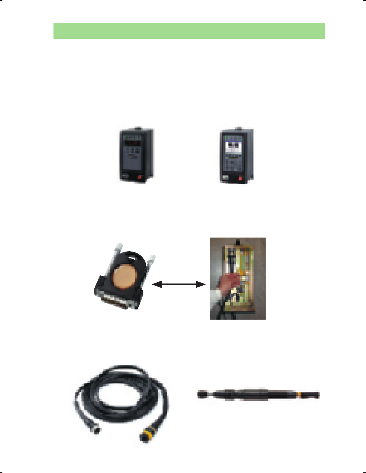
Putting together the Tensor system
Power Focus 4000 is the electric tool controller replacing the 3100
generation, as the control and monitoring system for Atlas Copco’s
Tensor and ETX electrical tools. This advanced fastening system
consists of:
– a Power Focus controller. Two different hardware versions are
available, where only the user interface differs between them
PF 4000 Compact PF 4000 Graph
– an RBU: This is the combined software backup memory and
software key. This ”Remote Backup Unit” is available in Gold, Silver,
Bronze, X and DS versions as standard
– and of course a cable and a tool. These are available in numerous
torque ranges and variants
3
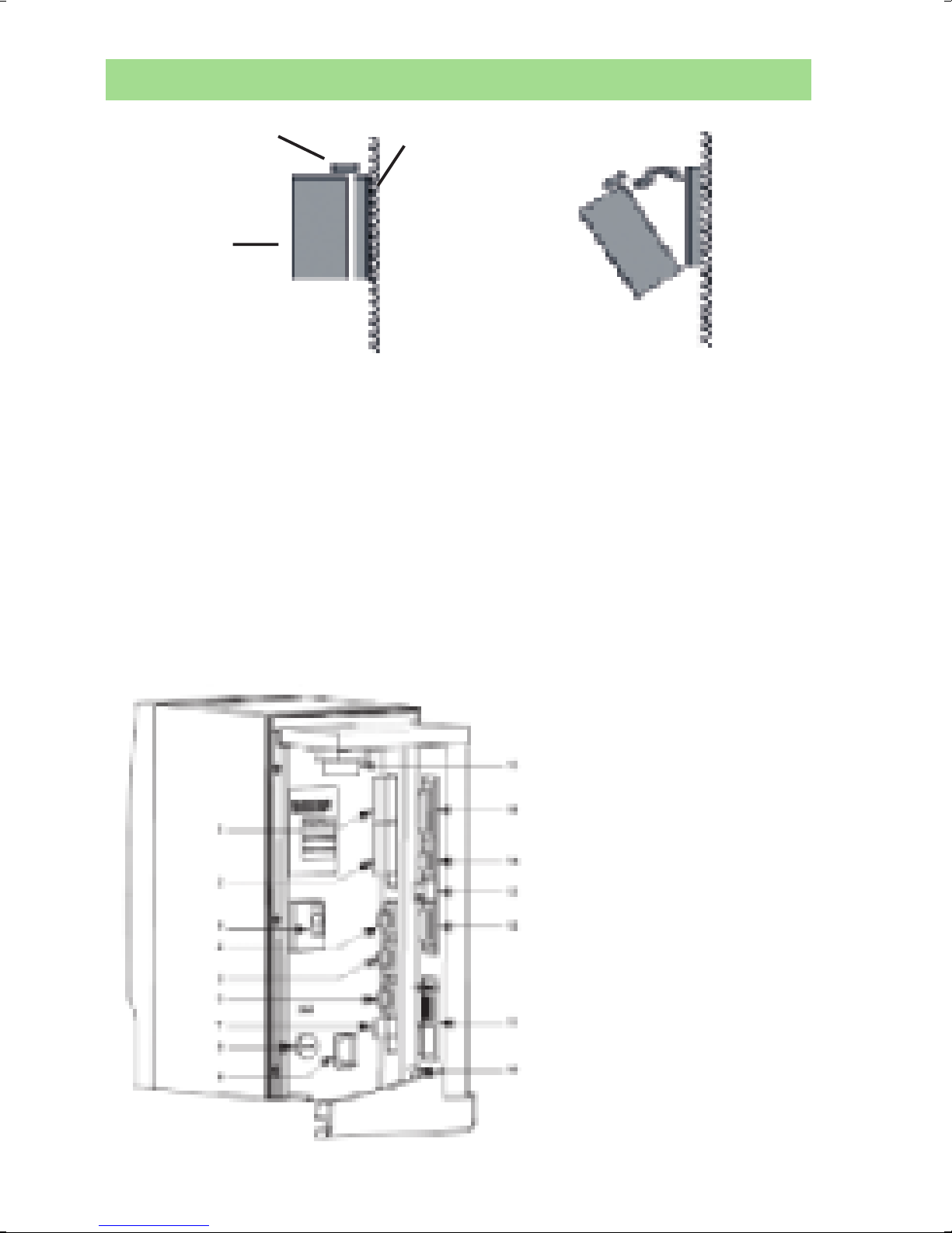
Mounting and connecting
Lock
Wall
Controller
1) Open the locking mechanism
2) Open the controller slowly towards you
3) Connect the tool cable, power cable etc. (see picture below)
4) Connect the RBU
5) Check that the GFI (Ground Fault Interruptor) is switched on
6) Close the controller and lock it
7) Connect the power cable to a power supply (115/230 V)
8) Turn the power on
IMPORTANT! Whenever replacing a tool, always turn the power off.
1. Digital input – Internal 24 V DC
2. Relays
3. Ground Fault Interrupter (GFI)
4. Serial #1 (RS232)
5. I/O Bus #1
6. I/O Bus #2
7. Remote start
8. Main fuse
9. Main power connector
10. Ground connection
11. Field bus card (optional)
12. RBU
13. Ethernet
14. Serial #2 (RS232)
15. Printer
16. Tool output
4
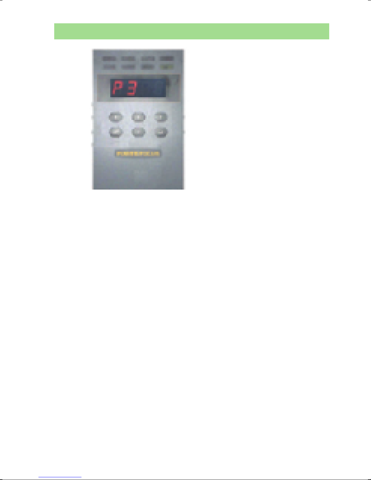
The Compact user interface
1 2 3 4
5 6 7 8
1. O K
2. NOK
3. Alarm
4. AutoSet
5. n x OK
6. Job OK
7. STAT
8. Prog Control
1. OK The tightening result is within specifi ed limits
2. NOK The tightening result is outside of specifi ed limits
3. ALARM Steady light means the alarm needs to be ac-
knowl- edged. Flashing light means no acknowledgment
is needed
4. AUTO SET The AutoSet programming routine is running
5. n x OK The no. of OK tightenings equals batch size
6. JOB OK A Job has been completed
7. STAT Any of the calculated values falls outside of the sta-
tistical limits
8. PROG CONTROL Steady light indicates an unlocked keypad.
Flashing green means that programming control is taken
by ToolsTalk PF
5

The Compact user interface
Button Functionality
Question mark Pressing it will show RBU type (Au = Gold, Ag =
Silver etc), installed software release, connected
tool type, active Pset and Job
F Press F (Function key) to display functions. To
display function F1 press F once, to display
function F2 press F twice etc. Press Enter to
access and edit a function. When fi nished, press
F repeatedly to display result mode again (or
else it will take 30 seconds for the screen to
update automatically)
Note: The functionality is dependent on the RBU
version.
F1 / Ft Final target
F2 / tunE Torque tune factor (DS mode only)
F3 / tool Motor tuning. Press and hold the tool trigger
until ”done” is shown
F4 / Pset Change the Pset (in cases where this has been
enabled)
F5 / batS Set the batch size (0 to 99)
F6 / DISC Disconnect tool. Await ”Safe to disconnect”
before disconnecting
F7 / stun Sync motor tuning. The LH no. shows the
percentage of sync members already tuned.
The RH no. shows the progress of the ongoing
tuning
F8 / Stun Controller IP address. Restart the PF after
changing the address
AutoSet Start AutoSet, set the target torque and
make tightenings on the actual joint to let the
controller program the tightening parameters
6
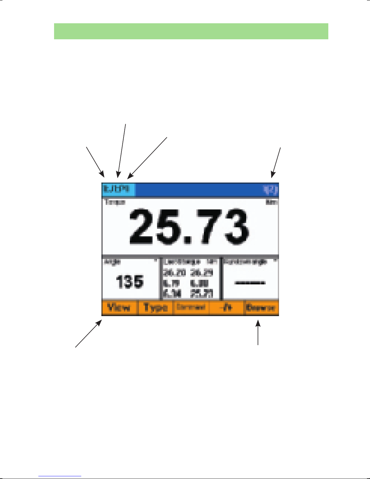
The Graph user interface
The color display offers easy monitoring and programming. It can
be confi gured to show information from any Power Focus within a
cell. The display is fully confi gurable - the picture below shows only
one example.
Channel
number
in the cell
Job no.
Pset (P) or Multistage (M) number
Batch count
no. and
(batch size)
Press View if you want
to see
- tightening traces
- statistics
- events
Press Browse if you
want to change the
view of the lower
right window, to see
for example the no.
of tightenings left in a
batch
7

ToolsTalk PF
Connect via USB
1) Turn on your PC and the PF, then 2) connect the USB cable. Your PC should detect
the PF, which makes it possible to start TTPF
and connect to the PF using the ”serial”
option. Otherwise you need to install a USB
driver, which is available on the installation
CD of TTPF.
Connect via Ethernet
Use a crossed Ethernet cable to connect directly to the PF,
alternatively use normal cables and an Ethernet switch. Then follow
these steps to set up the network.
- Connect the cables between the switch and the PF and between
the switch and the PC
- Set the IP address, e.g. [192.168.0.?] where ? can be between 0
and 255, and the subnet mask e.g. [255.255.255.0] of the PF unit(s)
over its keyboard. In the Graph, you do the setting under Controller
-> Communication, and in the Compact, the IP address is set under
F8. Each unit needs its own unique address, but the subnet mask
must be the same. Restart the Power Focus
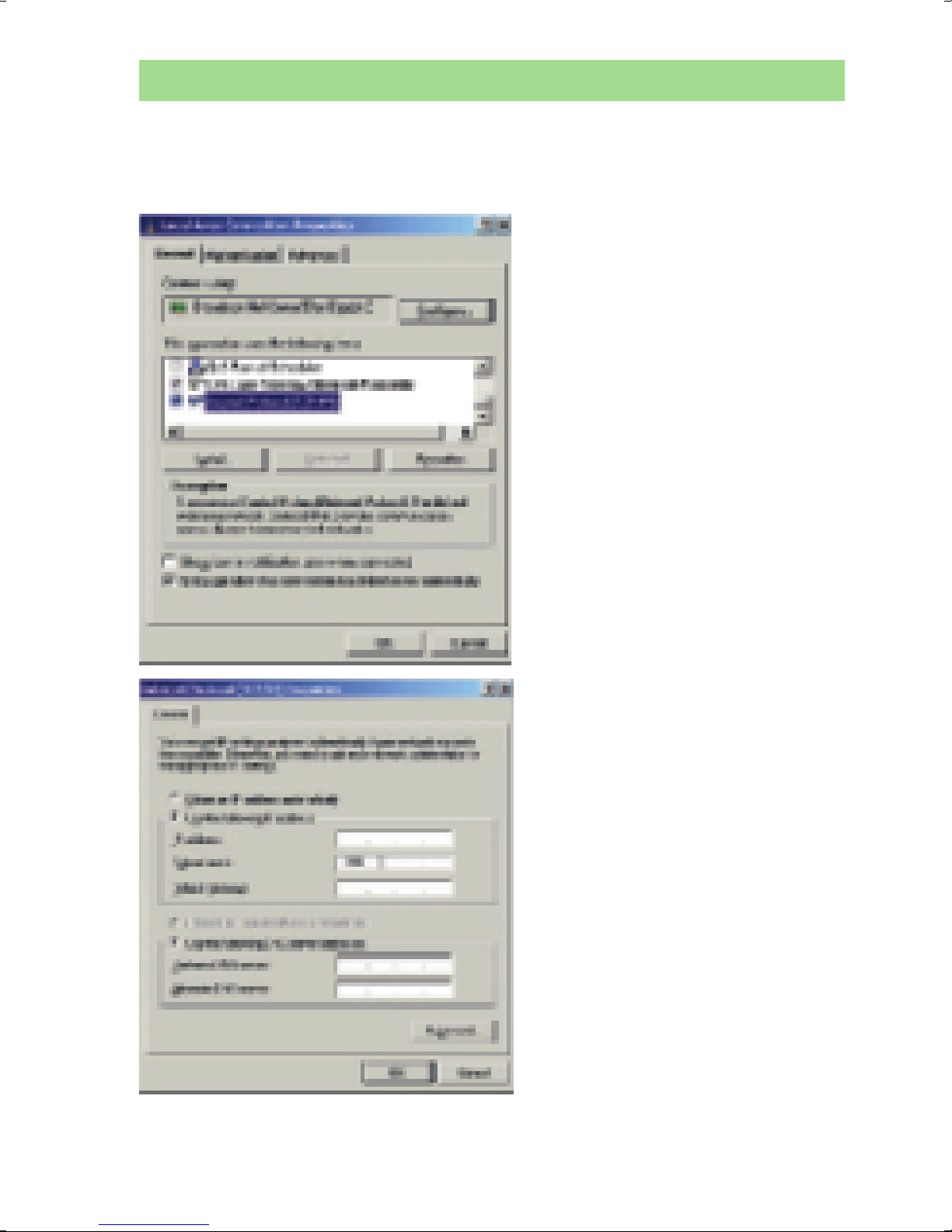
Then, set the IP address and subnet mask of your PC. Using
®
Windows XP
, this is done via My Computer -> Network
connections, where you right-click on Local Area Connection and
choose Properties. In the window that appears, select Internet
Protocol as indicated below, and click the button Properties. In the
window that appears, you set an IP address (unique) and the same
subnet mask as for the PF.
Remember to re-set your PC to the normal settings after the
session.
8
ToolsTalk PF
Connect via Ethernet continued
9
Setting up the normal two-stage tightening
Torque Control / Angle Monitoring – Two Stage
To quickly get started, either
1) make the basic settings using AutoSet
a) On the Compact, this is done by i) pressing the ”arrow” button, ii) confi rming by
pressing Enter, iii) entering the fi nal torque target with the ’+’ and ’-’ buttons, and iv)
confi rming with the Enter button
b) On the Graph, the fi nal torque target for AutoSet is entered under the menu item
Pset -> AutoSet
In both cases, you then just make tightenings on the desired joint until the AutoSet lamp
goes out
2) or you use QuickProg in ToolsTalk PF or on the Graph (selecting Pset -> Quick prog) if
you already have an idea of the joint hardness
10

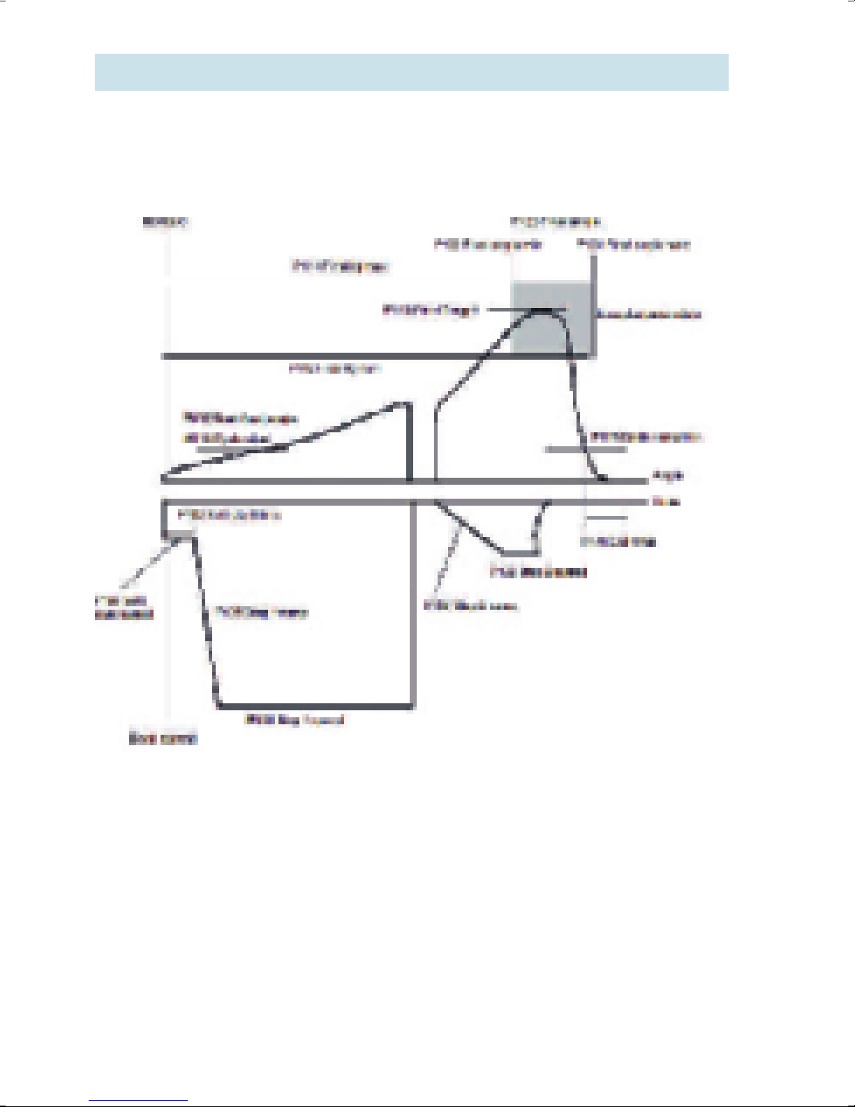
Monitoring the fi rst stage of your tightening
The Power Focus offers several ways to control and monitor the
rundown of the screw cycle. The rundown is the rotation before snug
level (where the screw head starts compressing the joint).
Rundown Monitoring: monitor the angle between cutting the
fi rst thread and a settable torque level
PVT Selftap: monitor torque during an angle window
in the beginning of the rundown
PVT Monitoring: monitor torque during an angle window
somewhere within the rundown phase
PVT Compensate: compensate for torque lost to e.g. thread
forming during rundown, measured in
real-time for each individual screw
Post-view torque: a more fl exible strategy, allowing a max
torque for a settable window and a min
torque for another window to be defi ned
during rundown
11
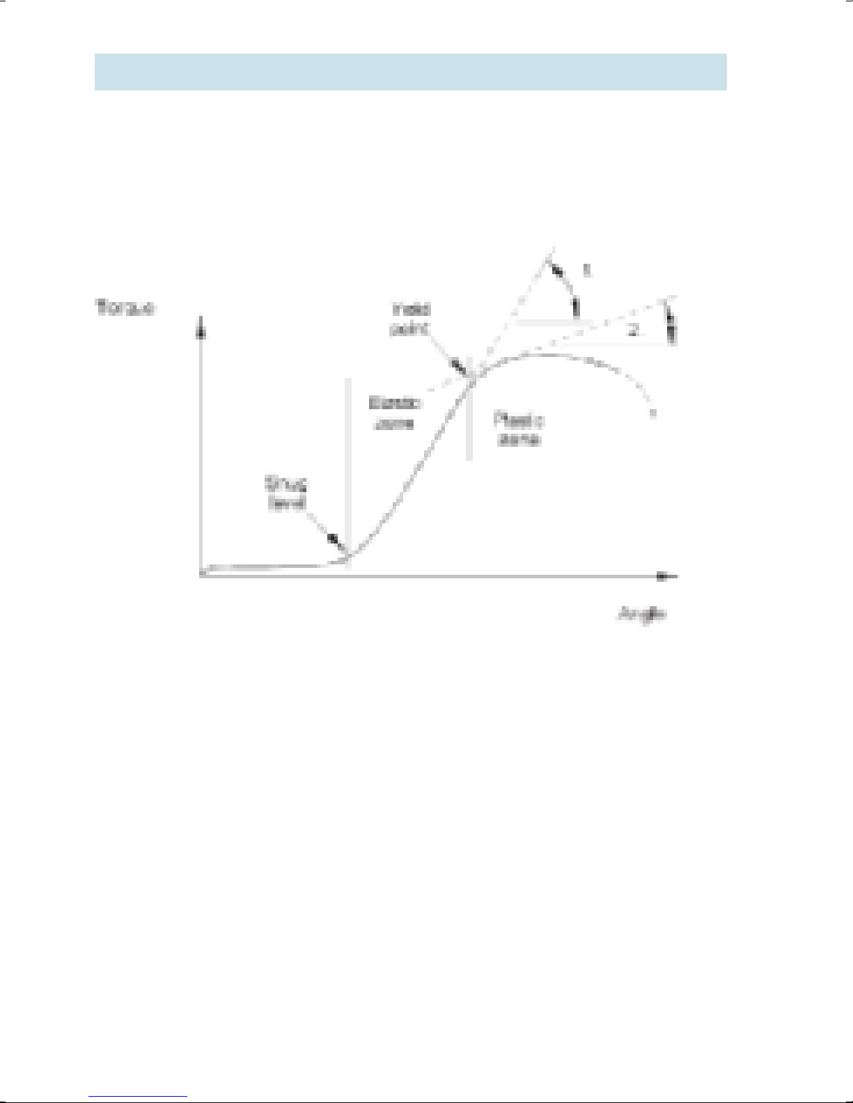
Yield control
Using Yield control as tightening strategy gives higher clamp force
out of the same screw, than with Torque control. A problem joint could
benefi t from a change of strategy, or it can be redesigned into smaller dimensions and lower weight, while meeting the same clamping
requirements.
Power Focus samples a fi ltered torque several times during the clamp
force build-up in the elastic zone of the screw. The increase (the difference) between the last and the third last mean torque is calculated.
If this increase is bigger than the previously biggest increase, it is
stored as the new shutoff reference (Tmax).
When the gradient decreases (approaching yield), the torque increase
will also get smaller, and fi nally go under the set percentage of Tmax
which is the criteria for tool shut-off.
12

Detecting a ”rehit”
At hand-held applications, there is always a risk that the operator
starts a tightening on an already tightened bolt. This can disturb the
station’s batch counting.
Power Focus has a rehit detection based on tool speed in the fi rst
stage, and tightening angle in the fi nal stage.
To NOT be judged as a rehit, the tightening must reach 25% of Step
1 Speed (P131) in the fi rst stage, OR have an angle between First
(P111) and Final Target (P113) of at least 121 degrees.
A rehit will render a NOK tightening result, although the torque and
angle might have fallen inside the set monitoring windows. The rehit
event can be put out on a relay or the fi eldbus for external process
control devices.
13
 Loading...