

Atlas Copco LF 2, LF 5, LF 3, LF 7, LF 10 Instruction Book

Atlas Copco
Industrial aluminium piston compressor
LF 2, LF 3, LF 5, LF 7, LF 10
Instruction book


Atlas Copco
Instruction aluminium pistion compressors
LF 2, LF 3, LF 5, LF 7, LF 10
Instruction book
Original instructions
Copyright Notice
Any unauthorized use or copying of the contents or any part thereof is prohibited.
This applies in particular to trademarks, model denominations, part numbers and
drawings.
This instruction book is valid for CE as well as non-CE labelled machines. It meets the
requirements for instructions specified by the applicable European directives as
identified in the Declaration of Conformity.
2012 - 05
No. 2920 7090 02
Replace No. 2920 7090 01
www.atlascopco.com

Instruction book
Table of contents
1 Safety precautions ...................................................................................................................... 4
1.1 Safety icons ....................................................................................................................... 4
1.2 Safety precautions, general ............................................................................................... 4
1.3 Safety precautions during installation ............................................................................... 4
1.4 Safety precautions during operation ................................................................................. 6
1.5 Safety precautions during maintenance or repair ........................ ..................................... 7
2 General description .................................................................................................................... 9
2.1 General description ........................................................................................................... 9
2.2 Operation ......................................................................................................................... 14
2.3 Air flow ............................................................................................................................. 15
2.4 Regulating system ........................................................................................................... 20
3 Installation .................................................................................................................................. 22
3.1 Dimension drawings ........................................................................................................ 22
3.2 Installation instruction ...................................................................................................... 36
3.3 Electrical Connections ..................................................................................................... 40
3.4 Settings of overload relay and fuses ......... ...................................................................... 41
3.5 Cable sizes ...................................................................................................................... 44
3.6 Pictographs ...................................................................................................................... 44
4 Operating Instructions ............................................................................................................ 45
4.1 Initial start –up ................................................................................................................. 45
4.2 Starting ............................................................................................................................ 45
4.3 Stopping........................................................................................................................... 47
4.4 Taking out of operation .................................................................................................... 47
2 2920 7090 00

Instruction book
4.5 Storage after installation .................................................................................................. 47
5 Maintenance ............................................................................................................................... 49
5.1 Petrol engine maintenance .............................................................................................. 49
5.2 Preventive maintenance schedule ....................... .... ........ .... ... .... ........ .... .... .... ........ .... .... 49
5.3 Service kits ...................................................................................................................... 50
5.4 Disposal of used material ................................................................................................ 50
6 Servicing and adjustment procedures ................................................................................ 51
6.1 Unloader or check valve .................................................................................................. 51
6.2 Valves .............................................................................................................................. 51
6.3 Air filter ............................................................................................................................. 53
6.4 Adjustment MDR4 pressure switch ..................................................................... .... .... .... 53
6.5 Adjustment MDR3 pressure switch ..................................................................... ........ .... 55
6.6 Adjustme nt of pilot valve on Trolley ................................................................................. 56
6.7 Safety valve ..................................................................................................................... 57
7 Problem solving ........................................................................................................................ 59
8 Technical data ............................................................................................................................ 61
8.1 Reference conditions ....................................................................................................... 61
8.2 Limitations ........................................................................................................................ 61
8.3 Compressor data ............................................................................................................. 61
9 Instructions for use .................................................................................................................. 64
10 Pressure Equipment Directive (PED) .................................................................................. 65
11 Declaration of conformity ....................................................................................................... 66
2920 7090 00 3
1 Safety precautions
Instruction book
1.1
Explanation
Safety icons
Danger for life
Warning
Important note
1.2 Safety precautions, general
General Precautions
1. The operator must employ safe working practices and observe all related work safety requirements and
regulations.
2. If any of the following statements does not comply with the applicable legislation, t he stricter of the two
shall apply.
3. Installation, operation, maintenance and repair work must only be performed by authorized, trained,
specialized personnel.
4. The compressor is not considered capable of producing air of breathing quality. For air of breathing quality,
the compressed air must be adequately purified according to the applicable legislation and standards.
5. Before any maintenance, repair work, adjustment or any other non-routine c hecks, stop th e dryer, press t he
emergency stop button, switch off the voltage and depressurize the dryer. In addition, the power isolati ng
switch must be opened and locked.
6. Never play with compressed air. Do not apply the air to your skin or direct an air stream at people. Never
use the air to clean dirt from your clothes. When using the air to clean equipment, do so with extreme
caution and wear eye protection.
7. The owner is responsible for maintaining the dryer in safe operating condition. Parts and accessories shall
be replaced if unsuitable for safe operation.
8. It is not allowed to walk or stand on the roof of the compressor canopy.
1.3 Safety precautions during installation
All responsibility for any damage or injury resulting from neglecting these precautions, or
non-observance of the normal precaution and care required for installation, operation,
maintenance and repair, even if not expressly stated, will be disclaimed by the manufacturer.
4 2920 7090 00

Instruction book
Precautions during installation
1. The dryer must only be lifted using suitable equipment and in accordance with the applicable safety
regulations. Loose or pivoting parts must be securely fastened before lifting. It is strictly forbidden to dwell
or stay in the risk zone under a lifted load. Lifting accel eration and deceleration must be kept within safe
limits. Wear a safety helmet when working in the area of overhead or lifting equipment.
2. Place the dryer where the ambient air is as cool a nd clean as possible. If necessary, install a suction duc t.
Never obstruct the air inlet. Care must be taken to minimize the entry of moisture at the inlet air.
3. Any blanking flanges, plugs, caps or desiccant bags must be removed before connecting the pipes.
4. Air hoses must be of correct size a nd su itable for the working pressure. Never u se fraye d, damage d or worn
hoses. Distribution pipes and connections must be of the correct size and suitable for the working pres sur e .
5. The aspirated air must be free of flammable fumes, vapours and particles, e.g. paint solvents, that can lead
to internal fire or explosion.
6. Arrange the air intake so that loose clothing worn by people cannot be sucked in.
7. Ensure that all piping is free to expand under heat and that it is not in contact with or close to flammable
materials.
8. No external force may be exerted on the air outlet valve. The connected pipe must be free of strain.
9. If remote control is installed, the machine must bear a clear sign stating "Danger: This machine is remotely
controlled and may start without warning".
The operator has to make sure that the machine is stopped and that the isolating switch is open and locked
before any maintenance or repair. As a further safeguard, persons switching on remotely controlled
machines shall take adequate precautions to ensure that there is no one checking or working on the machine.
To this end, a suitable notice shall be affixed to the starting equipment.
10. The machines must be installed in such a way that an adequate flow of cooling a i r is available a nd that
the air from the exhaust does not recirculate to the compressor air inlet or cooling air inlet..
11. The electrical connections must correspond to the applicable codes. The machines must be earthed and
protected against short circuits by fuses in all phases. A lockable power isolating switch must be installed
near the compressor.
12. On machines with automatic start-stop system or if the automatic restart function after voltage failure is
activated, a sign stating "This machine may start without warning" must be affixed near the instrument
panel.
13. In multiple compressor systems, manual valves must be installed to isolate each compressor. Non-return
valves (check valves) must not be relied upon for isolating pressure systems.
14. Never remove or tamper with the safety devices, guards or insulation fitted on the machine. Every pressure
vessel or auxiliary installed outside the machine to contain air above atmospheri c press ure must be pr otect ed
by a pressure-relieving device or device s as req ui red.
15. Pipework or other parts with a temperature in excess of 80˚C (176˚F) and which may be accidentally
touched by personnel during normal operation must be guarded or insulated. Other high-temperature piping
must be clearly marked.
16. If the ground is not level or can be subject to variable inclinations, consult the manufacturer.
Also consult following safety precautions: Safety precautions during operation and Safety
precautions during maintenance.
These precautions apply to machinery processing or consuming air or inert gas. Processing
of any other gas requires additional safety precautions typical to the application which are
not included herein.
Some precautions are general and cover several machine types and equipment; hence
some statements may not apply to your machine.
2920 7090 00 5

Instruction book
1.4 Safety precautions during operation
All responsibility for any damage or injury resulting from neglecting these precautions, or
non-observance of the normal precaution and care required for installation, operation,
maintenance and repair, even if not expressly stated, will be disclaimed by the manufacturer.
Precautions during operation
1. Use only the correct type and size of hose end fittings and connections. When blowing through a hose or air
line, ensure that the open end is held securely. A free end will whip and may cause injury. Make sure that a
hose is fully depressurized before disconnecting it.
2. Persons switching on remotely controlle d machines shall take adequate precautions to ensure that there is no
one checking or working on the machine. To this end, a suitable notice shall be affixed to the remote start
equipment.
3. Never operate the machine when there is a possibility of taking in flammable or toxic fumes, vapours or
particles.
4. Never operate the machine below or in excess of its limit ratings.
5. People staying in environments or rooms where the sound pressure level reaches or exceeds 90 dB(A) shall
wear ear protectors.
6. Periodically check that:
All guards are in place and securely fastened
All hoses and/or pipes inside the machine are in good condition, secure and not rubbing
There are no leaks
All fasteners are tight
All electrical leads are secure and in good order
Safety valves and other pressure-relief devices are not obstructed by dirt or paint
Air outlet valve and air net, i.e. pipes, couplings, manifolds, valves, hoses, etc. are in good condition, free
of wear or abuse
7. If warm cooling air from dryers is used in air heating systems, e.g. to warm up a working area, take
precautions against air pollution and possible contamination of the breathing air.
8. Do not remove any of, or tamper with, the sound-damping material.
9. Never remove or tamper with the safety devices, guards or insulations fitted on the machine. Every pressure
vessel or auxiliary installed outside the machine to contain air above atmospheric pressure shall be protected
by a pressure-relieving device or devices as required.
Also consult following safety precautions: Safety precautions during installation and Safety
precautions during maintenance or repair.
These preca utions ap ply to ma chiner y proces sing or consumin g air or i nert gas . Proc essing
of any other gas requires additional safety precautions typical to the application which are
not included herein.
Some precautions are general and cover several machine types and equipment; hence
some statements may not apply to your machine.
6 2920 7090 00

Instruction book
1.5 Safety precautions during maintenance or repair
All responsibility for any damage or injury resulting from neglecting these precautions, or
non-observance of the normal precaution and care required for installation, operation,
maintenance and repair, even if not expressly stated, will be disclaimed by the manufacturer.
Precautions during maintenance or repair
1. Always wear safety glasses.
2. Use only the correct tools for maintenance and repair work.
3. Use only genuine spare parts.
4. All maintenance work shall only be undertaken when the machine has cooled down.
5. A warning sign stating " W ork in progress - do not st art" shall be attached to the starting equipment.
6. Persons switching on remotely controlled machines shall take adequate precautions to ensure that there is no
one checking or working on the machi ne. To this end, a suitable notice shall be affixed to the re mote start
equipment.
7. Close the dryer air outlet valve before connecting or disconnecting a pipe.
8. Before removing any pressurized co mponent, effectively isolate the machine from all so urces of pressure
and relieve the entire system of pressure.
9. Never use flammable solvents or carbon tetrachloride for cleaning parts. Take safety precautions against
toxic vapours of cleaning liquids.
10. Scrupulously observe clea nliness duri ng maintenanc e and repair. Kee p dirt away by covering t he parts and
exposed openings with a clean cloth, paper or tape.
11. Never weld or perform any operation involving heat near the oil system. Oil tanks must be completely
purged, e.g. by steam-cleaning, before carrying out such operations. Never weld on, or in any way modify,
pressure vessels..
12. Whenever there is an indication or any suspicion that an internal part of a machine is overheated, the
machine shall be stopped but no inspection covers shall be opened before sufficient cooling time has
elapsed; this to avoid the risk of spontaneous ignition of the oil vapor when air is admitted.
13. Never use a light source with open flame for inspecting the interior of a machine, pressure vessel, etc.
14. Make sure that no tools, loose parts or rags are left in or on the machine.
15. All regulating and safety device s shall be maintained with due care to ens ure that they function properly.
They may not be put out of action.
16. Before clearing the machine for use after maintenance or overhaul, check that operating pressures,
temperatures and time settings are correct. Check that all control and shut-down devices are fitted and that
they function correctly. If removed, check that the coupling guard of the compressor drive shaft has been
reinstalled..
17. Protect the motor, electrical and regulating components, etc. to prevent moisture from entering the m, e.g.
when steam-cleaning.
18. Make sure that all sound-damping material and vibration dampers, e.g. damping material on the bodywork
and in the air inlet and outlet systems of the compressor, are in good condition. If damaged, replace it by
genuine material from the manufacturer to prevent the sound pressure level from increasing.
19. Never use caustic solvents which can damage materials of the air net, e.g. polycarbonate bowls.
20. The following safety precautions are stressed when handling refrigerant:
Never inhale refrigerant vapors. Check that the working area is adequately ventilated; if required, use
breathing protection.
Always wear special gloves. In case of refrigerant contact with the skin, rinse the skin with water. If
liquid refrigerant contacts the skin through clothing, never tear off or remove the latter; flush abundantly
with fresh water over the clothing until all refrigerant is flushed away; then seek medical first aid.
21. Protect hands to avoid injury from hot machine parts, e.g. during draining of oil.
2920 7090 00 7

Instruction book
Also consult following safety precautions: Safety precautions during installation and Safety
precautions during operation.
These preca utions ap ply to ma chiner y proces sing or consumin g air or i nert gas . Proc essing
of any other gas requires additional safety precautions typical to the application which are
not included herein.
Some precautions are general and cover several machine types and equipment; hence
some statements may not apply to your machine.
8 2920 7090 00
Instruction book
2 General description
2.1 General description
Introduction
LF are air-cooled, single-stage, two cylinder piston compressors delivering oil-free air. They are built for
effective working pressure up t o 1 0 bar.
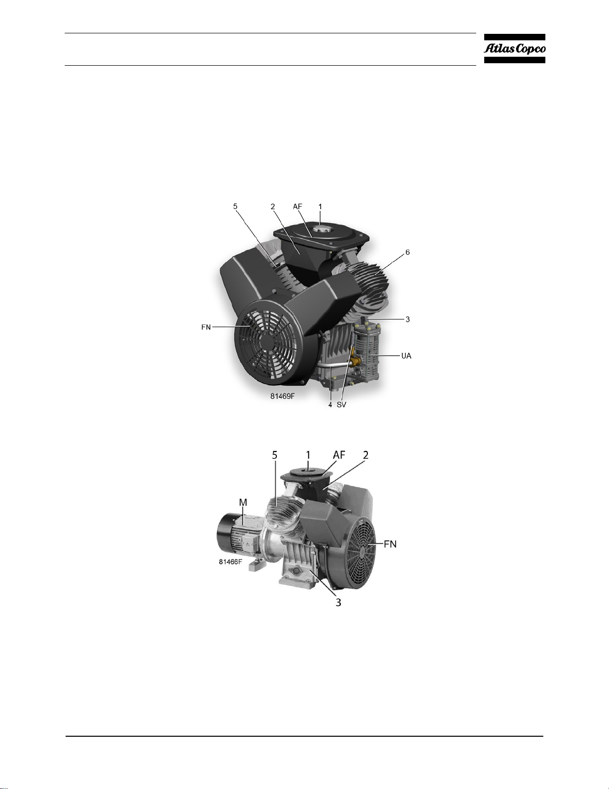
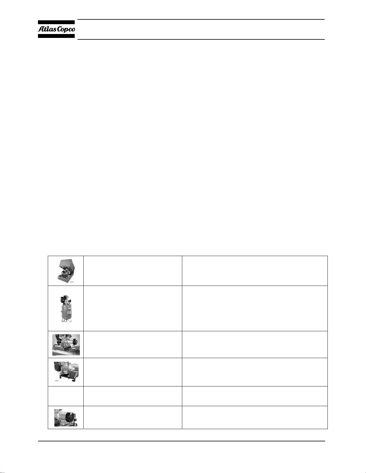
Compressor block with unloading valve
Power Pack
2920 7090 00 9
Instruction book
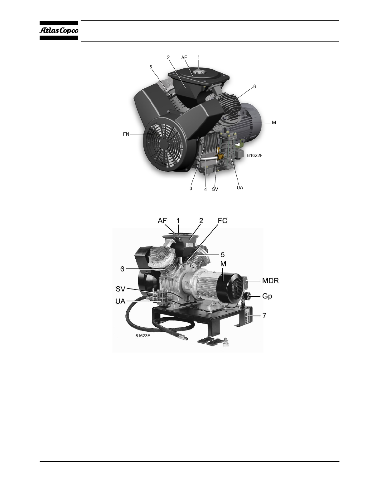
Power Pack with unloading valve
Base mounted
10 2920 7090 00
Instruction book
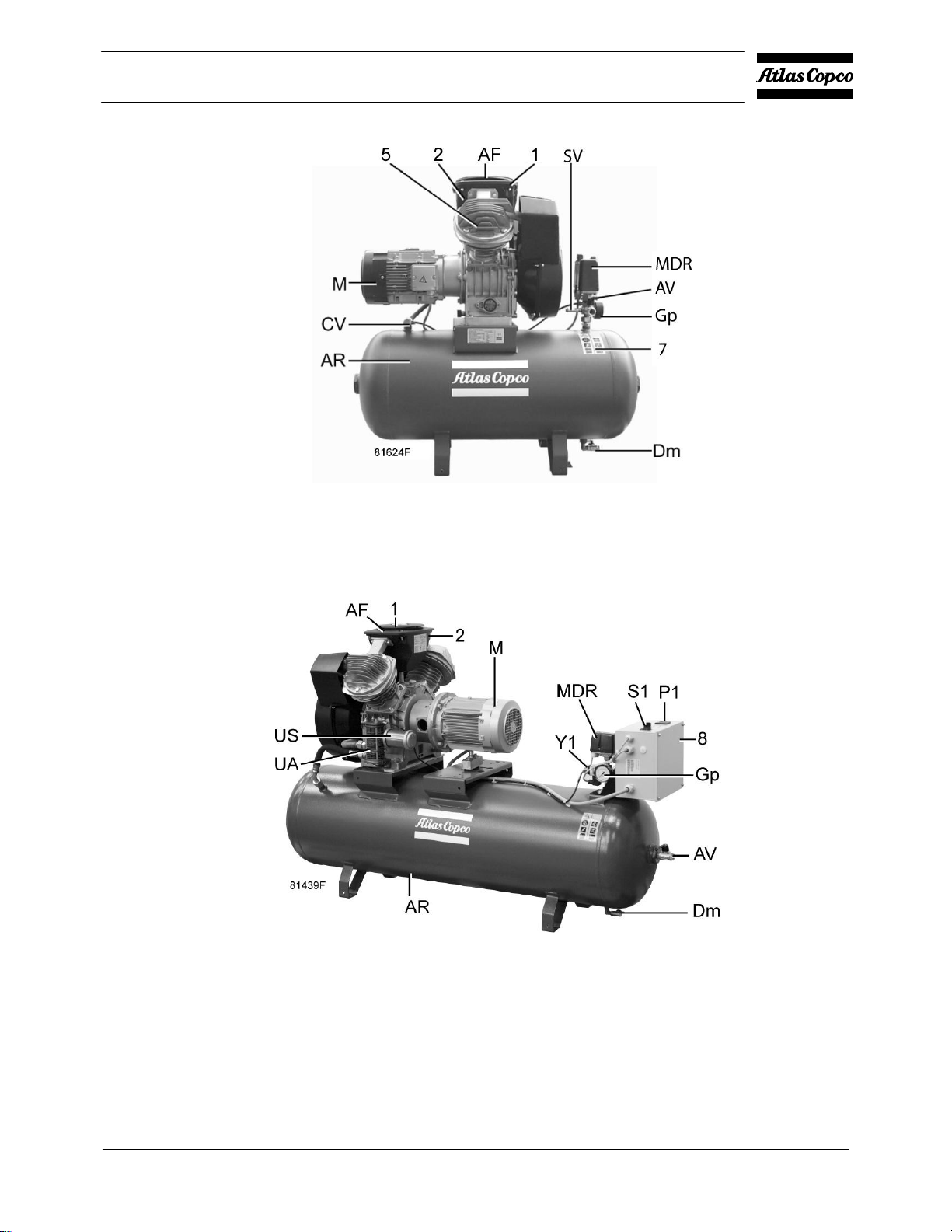
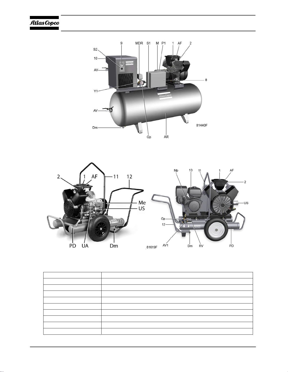
Tank- mounted, LF2 up to LF5, horizontal receiver
Tank mounted horizontal receiver
2920 7090 00 11
Instruction book
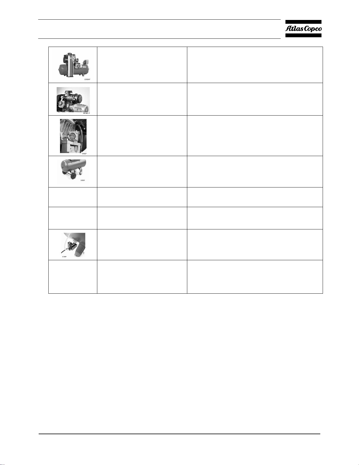
Tank- mounted, Full-Future unit, 475 l receiver
LF Trolley Petrol/Electri c
Reference
AF
AR
AV
CV
Dm
Dp
FC
FN
Gp Air pressure gauge
Description
Air filter
Air receiver
Air outlet valve
Check valve
Condensate drain valve
Oil drain plug
Filler cap
Fan
12 2920 7090 00
Instruction book
Reference
M
MDR
Me
Mp
P1
PD
RV
S1
S2
SG
SV
UA
US
Y1
Description
Motor
Air pressure switch
Electric motor
Petrol engin e
Hourmeter, running time
Pulsation damper
Pilot valve
On/off switch
On/off switch dryer
Oil sight glass
Safety valve
Unloader
Blow-off silencer
Loading solenoid valve
Reference
1 Cover
2 Air inlet silencer
3 Crankcase
4 Cooling pipe
5 Left cylinder
6 Right cylinder
7 Pictograph, see Pictographs
8 Electric cabinet
9 Dewpoint indicator
10 Refrigerant dryer
11 Lifting yoke
12 Towing handle
13 Fuel tank
Compressor variants
The Power Pack comprises
The compressor block includes:
Crankcase (3) and cylinders (5) and (6)
Air inlet filter (AF) and inlet silencer (2)
Fan (FN)
Air cooler piping
Check valve (CV) or Unloader (UA)
Safety valve (SV)
Description
2920 7090 00 13
Instruction book
For LF 2 up to LF 3: The compressor block as described above, with flanged-on electric motor (M), c heck
valve (CV) and safety valve (SV).
For LF 5 up to LF 10: the Compressor Block as described above, with flanged-on electric motor (M) and
solenoid valve (Y1)
The tank-mounted unit comprises:
For LF 2 up to LF 3: Th e Power pack mounted on a hori zontal or vertic al air recei ver (AR) with air outlet
valve (AV), pressure gauge (Gp), safety valve (SV), air pressure switch with an on/off button (MDR) and
condensate drain valve (Dm).
For LF 5 up to LF 10: The power pack mounted on an air receiver (AR) with air outlet valve (AV),
pressure gauge (Gp), safety valve (SV), and condensate drain valve (Dm). An electric cubicle (8) includes
the motor starter. A separate air pressure switch (MDR) is provided.
The base-mounted unit is a fully operational unit with air pressure switch and on/off switches
mounted on a frame (no air receiver).
LF Trolley units are mobile compressors. They are equipped with either a directly flanged electric motor or a
petrol engine. The compressors have two outlet connections:
A connection for compressed air at working pressure.
A connection for compressed air at reduced pressure via a pressure regulator.
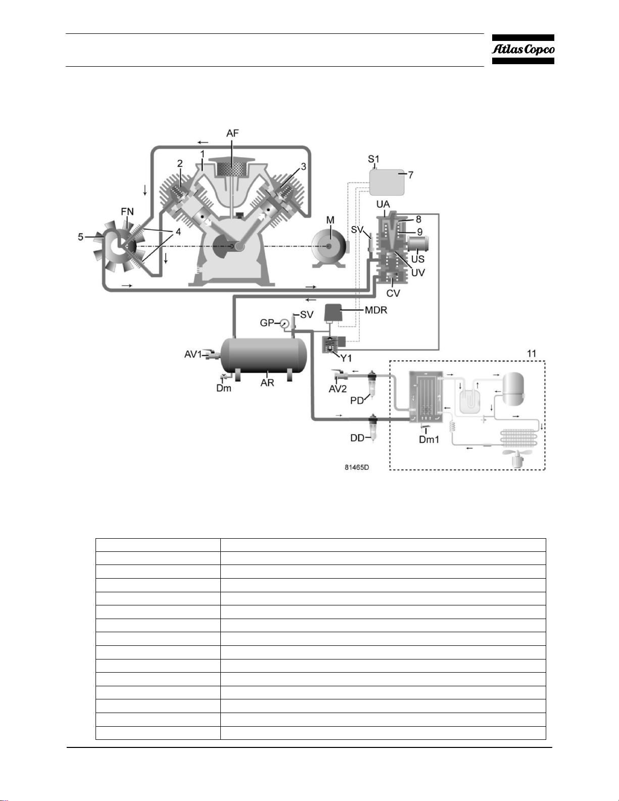
The Full-Feature compressor is a tank-mounted compressor provided with a Refrigerant dryer with DD & PD
filter. They remove moisture from compressed air by cooling the air to near freezing point. This causes water to
condense. The condensate is automatically drained. The air is warmed up before leaving the dry er.
2.2 Operation
The compressors are extendible with the following options. For detailed information consult Atlas Copco.
For 90 / 250 /475 Tank Mounted and Base Mounted
Silencing hood
Receiver upgrade
Pneumatic drain Not available for Trolley versions
Interstage drain Not available
Transformer
Motor anti-condensation heaters and
thermistor protection
Units
Receiver size upgrade
90 to 250 Standard Receiver
Vertical Receiver
upgrade 90 or 250 to 250
Only for 2 and 3hp
475 Receiver
upgrade 90 or 250 to 475
100VA (for c ubicle control voltage 400/3/50)
YD only
Used with LF 2-10 wi th 400V/50Hz and
460V/60Hz
14 2920 7090 00
Instruction book
CD adsorption dryer
Heavy duty air inlet filter
Oil level switch
Receiver wheel set
Auto restart
Power supply cable
(3 m)
LF 2-3 on 90 and 250 receiver
For PP-BM-TM-FF versions
Not available for LF
Wheelset for 90/250 receiver
with red CEE 3-pole plug 16A L = 3 mtr
offload valve (solenoid valve to make sure unit will
start after powe r f ailure)
Timer drain
(solenoid operated)
Used For DOL 230v/50hz and
400v/50hz Units
Invalid Combinations for Any other voltages or
frequencies and YD units
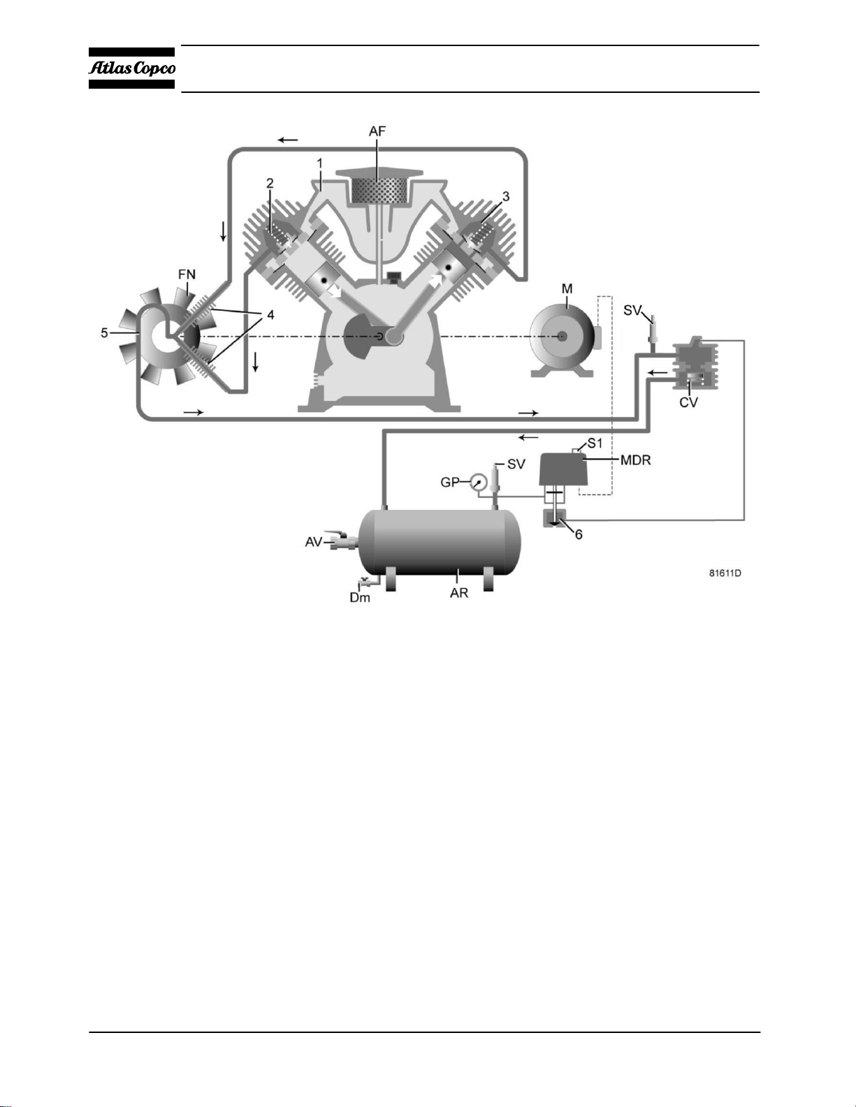
2.3 Air flow
LF 2 up to LF 10
Air drawn through air filter (AF) and inlet silencer (1) into cylinders (2 and 3) is compressed, then discharged
through cooler piping (4) and (5) and check valve (CV) / unloader valve (UA) into air receiver (AR).
2920 7090 00 15
Instruction book
Air flow and regulating system with DOL starter
16 2920 7090 00
Instruction book
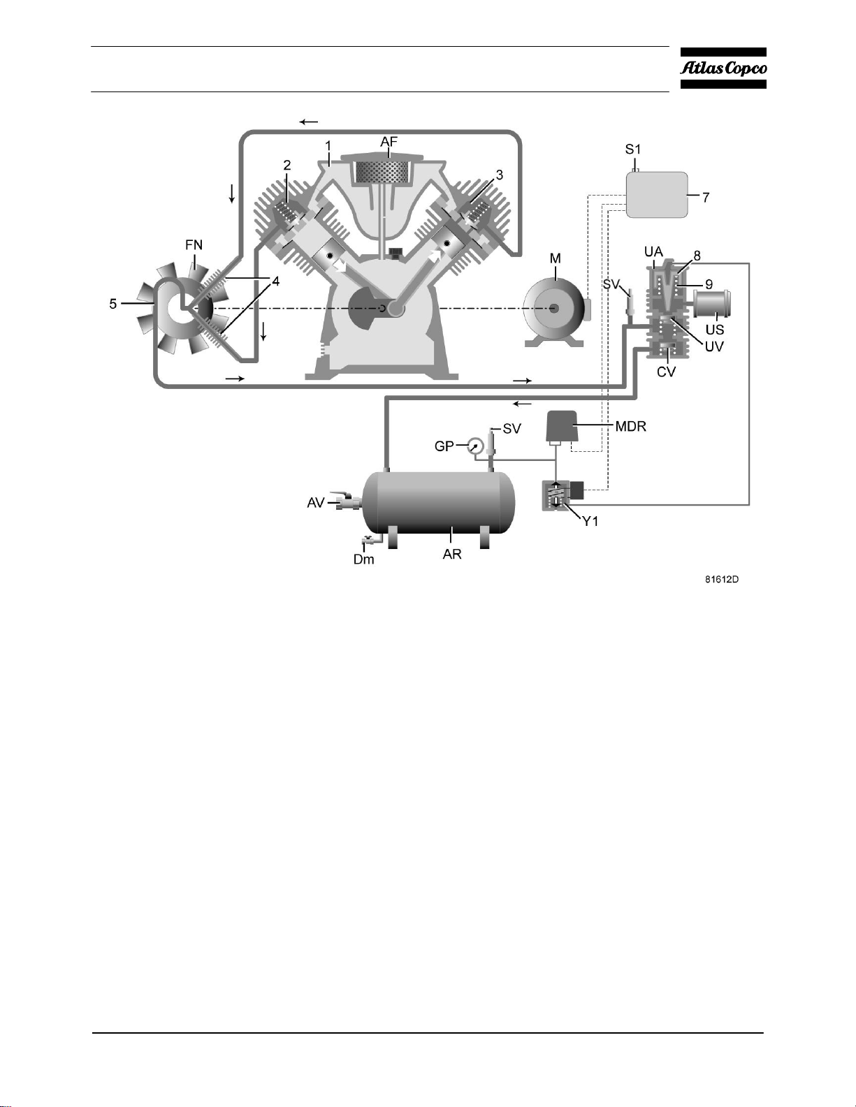
Air flow and regulating system with Y/D starter
2920 7090 00 17
Instruction book
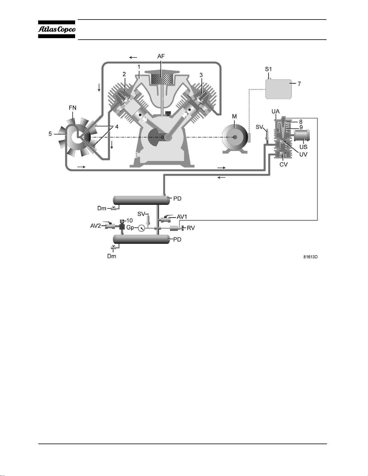
Air flow and regulating system of trolley
18 2920 7090 00
Instruction book
Full-Feature
Air flow and regulating system, Full-Feature
References on flow diagrams
Reference
AF
AR
AV
AV/AV2
CV
Dm
FC
FN
Gp Air pressure gauge
M Motor
MDR Air pressure switch
PD Pulsation damper
S1 On/off switch
RV Pilot valve
2920 7090 00 19
Description
Air filter
Air receiver
Air outlet valve
Air outlet valves
Check valve
Condensate drain valve
Oil filter cap
Fan
Instruction book
Reference
SV
UA
UV
US
Y1
Reference
R
2
3
4
5
6
7
8
9
10
11
Description
Safety valve
Unloader
Unloading valve
Blow-off silencer
Loading solenoid valve
Description
Air inlet silencer
Left cylinder
Right cylinder
Cooler
Cooling pipe
Pressure release valve
Electrical cubicle
Plunger
Spring
Pressure regulator
Refrigerant dryer
2.4 Regulating system
LF 2 up to LF 10 with DOL starter
The regulating system includes:
Check valve (CV)
Air pressure switch (MDR) with pressure release valve (6) and on/off button (S1).
For 10 to 20 Hp also Sol valve (for quicker discharge of head)
Operation
Air pressure switch (MDR) opens and closes its contacts at pre-set pressures. During loaded operation, the
contacts are closed: the motor is running.
When the pressure in the air receiver reaches the pre-set maximum pressure, the contacts as well as pressure
release valve (6) are opened. The motor stops, the air at the delivery side of the compressor is vented to
atmosphere and check valve (CV) closes to prevent venting of the receiver.
When the pressure in the air receiver decreases to the pre-set minimum pressure, the contacts of the air
pressure switch close and pressure release valve (6) closes. The motor restarts and compressed air is
supplied to the receiver again.
LF 2 up to LF 10 with Y/D starter
The regulating system includes:
20 2920 7090 00

Instruction book
Electric cubicle
Air pressure switch (MDR)
On/off switch (S1)
Solenoid valve (Y1)
Unloader (UA) with integrated check valve
Operation
Air pressure switch (MDR) opens and cl oses its contacts at pre-set pressures. During loaded operation, the
contacts are closed: the motor i s running and solenoid valve (Y1) is energized preventing the compressed
air from flowing to unloader (UA).
When the pressure in the air receiver reaches the pre-set maximum pressure, the contacts of pressure switch
(MDR) open. The motor stops and solenoid valve (Y1) is de-energized. Compressed air from the receiver
will flow via the solenoid valve to plunger (8) which causes unloading valve (UV) to open. The air at the
delivery side of the compressor is blown through silencer (US) to atmosphere and ch eck valve (CV) clos es
to prevent venting of the receiver.
When the pressure in the air receiver decreases to the pre-set minimum pressure, the contacts of the pressure
switch close. The motor restarts and, after switching over from star to delta, solenoid valve (Y1) is
energized. Control air from the unloader plunger chamber is vented to the atmosphere. Unloading valve
(UV) closes and compressed air is supplied to the receiver again.
LF Trolley up to 15 bar
The regulating system includes:
Pilot valve (RV)
Unloader (UA) with integrated check valve (CV)
Electric cabine (only on electric motor driven Trolley compressors)
Operation
Pilot valve (RV) opens and closes at pre-set pressures. During loaded operation, pilot valve (RV) is closed
preventing the compressed air from flowing to u nload er (UA) .
When the pressure in the pulsation da mpers (PD) reaches the pre- set maximum pressure, pilot val ve (RV)
will open. Compressed air from the pulsation dampers will flow to plunger (8) which causes unloading
valve (UV) to open. The air at the delivery side of the compressor is blown through silencer (US) to
atmosphere and check valve (CV) closes to prevent venting of the pulsation dampers. The compress or runs
unloaded.
When the pressure in the pulsation dampers decreases to the pre-set minimum pressure, the pilot valve
closes. Control air fro m the unloader plun ger chamber is vente d to the atmosphere. Unloading valve (U V)
closes and compressed air is supplied to the pulsation dampers again.
2920 7090 00 21
 Loading...