

Atlas Copco LE15, LE75, LE22, LE150, LE110 Instruction Book
...
Atlas Copco Stationary Air Compressors
*2920125704*
No. 2920 1257 04
Registration code: APC L / 38 / 989
Replaces 2920 1257 03
2000-10
LE/LT15, -22, -40, -55, -75, -110, -150
LF15, -22, -40, -55, -75
www.atlascopco.com
• Copyright 2000, Atlas Copco Airpower n.v., Antwerp, Belgium.
Any unauthorized use or copying of the contents or any part thereof is prohibited. This applies in
particular to trademarks, model denominations, part numbers and drawings.
• This instruction book meets the requirements for instructions specified by the machinery directive
98/37/EC and is valid for CE as well as non-CE labelled machines.
Instruction Book

2920 1257 04
2
Instruction book
This instruction book describes how to handle the machines to ensure safe operation, optimum efficiency and long service life.
Read this book before putting the machine into operation to ensure correct handling, operation and proper maintenance
from the beginning. The maintenance schedule comprises measures for keeping the machine in good condition.
Keep the book available for the operator and make sure that the machine is operated and that maintenance is carried out
according to the instructions. Record all operating data, maintenance performed, etc. in an operator's logbook available from
Atlas Copco. Follow all relevant safety precautions, including those mentioned on the cover of this book.
Repairs must be carried out by trained personnel from Atlas Copco who can be contacted for any further information.
In all correspondence mention the type and the serial number, shown on the data plate.
For all data not mentioned in the text, see sections "Preventive maintenance schedule" and "Principal data".
The company reserves the right to make changes without prior notice.
4.2 Preventive maintenance schedule for the
compressor . . . . . . . . . . . . . . . . . . . . . . . . . . . . . 34
4.3 Lubrication of LE/LT compressors. . . . . . . . . . . 35
4.4 Service kits . . . . . . . . . . . . . . . . . . . . . . . . . . . . . 35
5 Servicing and adjustment procedures . . . . . . . . . . 36
5.1 Unloader or check valve . . . . . . . . . . . . . . . . . . . 36
5.2 Valves . . . . . . . . . . . . . . . . . . . . . . . . . . . . . . . . . 36
5.3 Air filter . . . . . . . . . . . . . . . . . . . . . . . . . . . . . . . 37
5.4 Adjustment MDR4 pressure switch . . . . . . . . . . 37
5.5 Adjustment MDR5/6 pressure switch . . . . . . . . . 39
5.6 Adjustment pilot valve on Trolley . . . . . . . . . . . 39
5.7 Safety valve. . . . . . . . . . . . . . . . . . . . . . . . . . . . . 40
5.8 Relief valve on LF55/75, LE75 up to -150
and LT . . . . . . . . . . . . . . . . . . . . . . . . . . . . . . . . . 40
6 Problem solving. . . . . . . . . . . . . . . . . . . . . . . . . . . . . 41
7 Principal data . . . . . . . . . . . . . . . . . . . . . . . . . . . . . . 42
7.1 Reference conditions . . . . . . . . . . . . . . . . . . . . . 42
7.2 Limitations . . . . . . . . . . . . . . . . . . . . . . . . . . . . . 42
7.3 Compressor data for LE 10 bar . . . . . . . . . . . . . 42
7.3.1 50 Hz . . . . . . . . . . . . . . . . . . . . . . . . . . . . 42
7.3.2 60 Hz . . . . . . . . . . . . . . . . . . . . . . . . . . . . 43
7.4 Compressor data for LF 10 bar. . . . . . . . . . . . . . 43
7.4.1 50 Hz . . . . . . . . . . . . . . . . . . . . . . . . . . . . 43
7.4.2 60 Hz . . . . . . . . . . . . . . . . . . . . . . . . . . . . 44
7.5 Compressor data for LT 15 bar. . . . . . . . . . . . . . 44
7.5.1 50 Hz . . . . . . . . . . . . . . . . . . . . . . . . . . . . 44
7.5.2 60 Hz . . . . . . . . . . . . . . . . . . . . . . . . . . . . 45
7.6 Compressor data for LT 20 bar. . . . . . . . . . . . . . 45
7.6.1 50 Hz . . . . . . . . . . . . . . . . . . . . . . . . . . . . 45
7.6.2 60 Hz . . . . . . . . . . . . . . . . . . . . . . . . . . . . 46
7.7 Compressor data for LT 30 bar. . . . . . . . . . . . . . 46
7.7.1 50 Hz . . . . . . . . . . . . . . . . . . . . . . . . . . . . 46
7.7.2 60 Hz . . . . . . . . . . . . . . . . . . . . . . . . . . . . 47
8 Conversion list of SI units into US/British units . . 48
Contents
Page
1 Leading particulars . . . . . . . . . . . . . . . . . . . . . . . . . . 3
1.1 General description. . . . . . . . . . . . . . . . . . . . . . . . 3
1.1.1 Compressor variants . . . . . . . . . . . . . . . . . 3
1.2 Air flow. . . . . . . . . . . . . . . . . . . . . . . . . . . . . . . . . 3
1.2.1 LE/LF15 up to -40, LE55 and
LE75 50 Hz . . . . . . . . . . . . . . . . . . . . . . . . 3
1.2.2 LE75 60 Hz, LE110/150, LF55/75 and
LT . . . . . . . . . . . . . . . . . . . . . . . . . . . . . . . . 3
1.3 Regulating system. . . . . . . . . . . . . . . . . . . . . . . . . 3
1.3.1 LE/LF/LT15 up to -55 with DOL starter . . 3
1.3.2 LE/LT40 up to -150, LF40 up to -75,
each with Y/D starter. . . . . . . . . . . . . . . . . 6
1.3.3 LE/LF/LT Trolley . . . . . . . . . . . . . . . . . . . 8
2 Installation and handling . . . . . . . . . . . . . . . . . . . . . 10
2.1 Dimension drawings . . . . . . . . . . . . . . . . . . . . . . 10
2.2 Installation proposals . . . . . . . . . . . . . . . . . . . . . 25
2.2.1 LE/LF/LT . . . . . . . . . . . . . . . . . . . . . . . . . 27
2.2.2 LE/LF/LT Trolley . . . . . . . . . . . . . . . . . . 27
2.3 Electrical connections. . . . . . . . . . . . . . . . . . . . . 27
2.4 Settings of overload relay - fuses - cable size . . 30
2.4.1 Settings of overload relay - fuses of
compressors with DOL starter. . . . . . . . . 30
2.4.2 Settings of overload relay - fuses of
compressors with Y-D starter . . . . . . . . . 31
2.4.3 Cable size . . . . . . . . . . . . . . . . . . . . . . . . 32
2.5 Pictographs . . . . . . . . . . . . . . . . . . . . . . . . . . . . . 32
3 Operating instructions . . . . . . . . . . . . . . . . . . . . . . . 32
3.1 Initial start-up . . . . . . . . . . . . . . . . . . . . . . . . . . . 32
3.2 Starting . . . . . . . . . . . . . . . . . . . . . . . . . . . . . . . . 32
3.3 Stopping . . . . . . . . . . . . . . . . . . . . . . . . . . . . . . . 33
3.4 Taking out of operation at end of compressor
service life. . . . . . . . . . . . . . . . . . . . . . . . . . . . . . 33
4 Maintenance . . . . . . . . . . . . . . . . . . . . . . . . . . . . . . . 34
4.1 Petrol engine maintenance . . . . . . . . . . . . . . . . . 34

2920 1257 04
3
Instruction book
1 Leading particulars
1.1 General description
LE, LF and LT are air-cooled, single-acting piston
compressors. LE and LT are lubricated compressors; LF are
oil-less compressors which deliver oil-free air. LF15 up to
LF40, LE15 up to LE55 and LE75 50 Hz are single-stage
compressors; LE75 60 Hz, LE110/150, LF55/75 and LT are
two-stage compressors.
LE/LF/LT15 up to -55 and LE/LT75 50 Hz are two-cylinder
compressors, LE/L T75 60 Hz, LF75, LE/L T1 10-150 are threecylinder compressors.
Note: Take care that three-cylinder compressors rotate in the
direction as indicated by the arrow on the fan housing (counterclockwise seen from fan cowl side).
LE/LF are built for effective working pressures up to 10 bar.
L T are built for effective working pressures up to 30 bar (L T15
only for 15 and 20 bar).
1.1.1 Compressor variants
The Compressor Block (Fig. 1.1) includes:
- Crankcase (4) and cylinders (6)
- Air inlet filter (AF) and inlet silencer (3)
- Fan (FN)
- Air cooler piping (2) and (5)
- Unloader (7, as standard on LE/LF/LT40 up to -75, LE/
LT110 and LE150)
- Interstage relief valve (8, for LF55/75, LE75 60Hz, LE110/
150 and LT)
The Power Pack comprises (Figs. 1.2/1.3):
- For LE/LF/LT15 and -22: the Compressor Block as
described above, with flanged-on electric motor (M), check
valve (CV-Fig. 1.4) and air pressure switch with on/off
switches (13-Fig. 1.4).
- For LE/LF/LT40 up to -75, LT/LF110-150: the
Compressor Block as described above, with flanged-on
electric motor (M) and solenoid valve (Y1-Fig. 1.6).
The Complete Unit comprises:
- For LE/LF/LT15 and -22: the Power Pack mounted on a
horizontal (Fig. 1.4) or vertical (Fig. 1.5) air receiver (AR)
with air outlet valve (A V), pressure gauge (Gp), safety valve
(SV), air pressure switch with on/off switches (13) and
condensate drain valve (Dm).
- For LE/LF/L T40 up to -75, LE/L T1 10-150 (Fig. 1.6/1.7):
the Power Pack mounted on an air receiver (AR) with air
outlet valve (AV), pressure gauge (Gp), safety valve (SV)
and condensate drain valve (Dm). An electric cubicle (6)
includes the motor starter. A separate air pressure switch
(13) is provided.
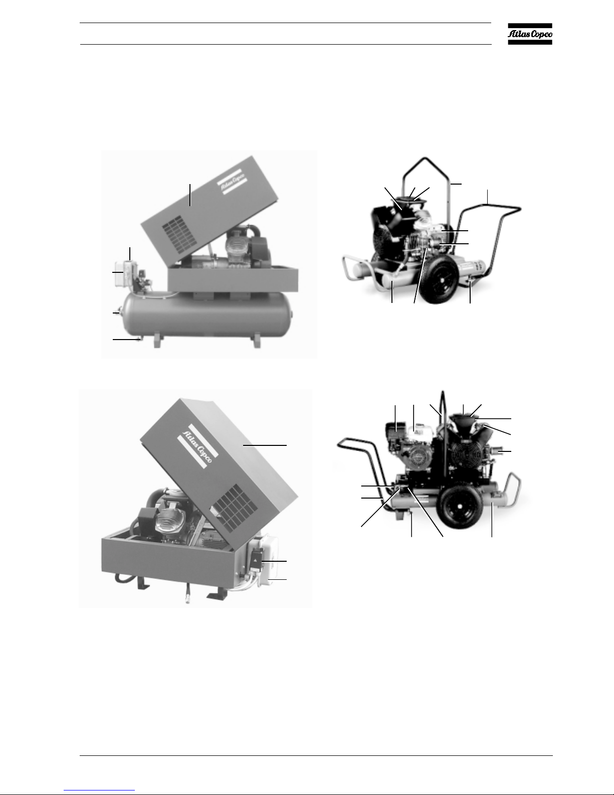
A silencing canopy (1-Fig. 1.13) is available as an option.
The canopy has a hinged top to allow easy access for
maintenance.
The Unsilenced Pack Unit (Fig. 1.8) is a fully operational
unit mounted on a frame (no air receiver). A silencing hood
can be added as an option
LE, LF and L T Trolley units (Figs. 1.15 and 1.16) are mobile
compressors. They are equipped with either a directly flanged
electric motor (LE/LF/L T ETROL Fig. 1.15) or a petrol engine
(LE/LF/LT PETROL Fig. 1.16). The compressors have two
outlet connections:
- a connection for compressed air at working pressure
- a connection for compressed air at reduced pressure via a
pressure regulator
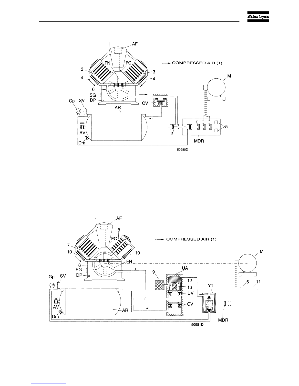
1.2 Air flow
1.2.1 LE/LF15 up to -40, LE55 and LE75 50 Hz
(Fig. 1.10)
Air drawn through air filter (AF) and inlet silencer (1) into
cylinders (3) is compressed, then discharged through cooler
piping (4) and (6) and check valve (CV) into air receiver (AR).
1.2.2 LE75 60 Hz, LE110/150, LF55/75 and LT
(Fig. 1.11)
Air drawn through air filter (AF) and inlet silencer (1) into LP
(low-pressure) cylinder(s) (7) is compressed, then discharged
to HP (high-pressure) cylinder (8) via intercooler (10).
The air is further compressed and discharged through cooler
piping (6) and check valve (CV) into air receiver (AR).
1.3 Regulating system
1.3.1 LE/LF/LT15 up to -55 with DOL starter
(Fig. 1.10)
The regulating system includes:
- Check valve (CV)
- Air pressure switch (MDR) with pressure release valve
(2) and on/off switches (5).
Operation
Air pressure switch (MDR) opens and closes its contacts at
pre-set pressures. During loaded operation, the contacts are
closed: the motor is running.

2920 1257 04
4
Instruction book
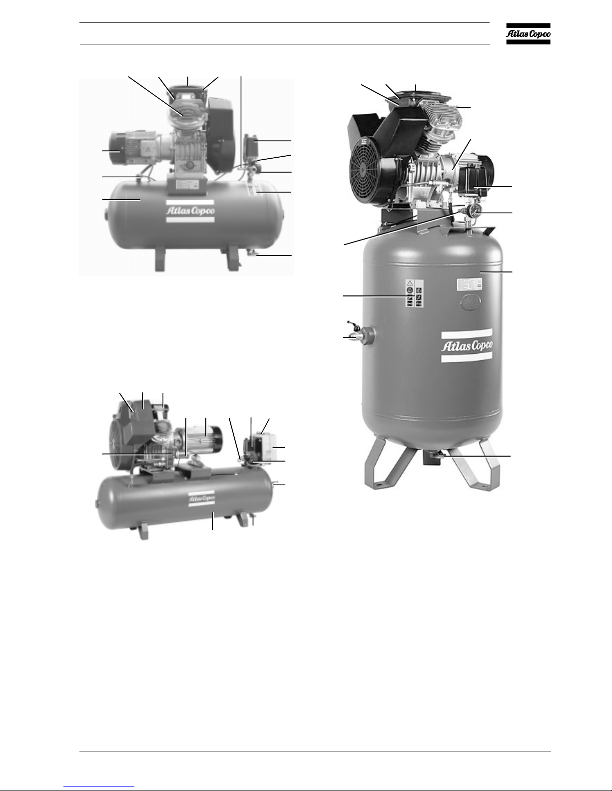
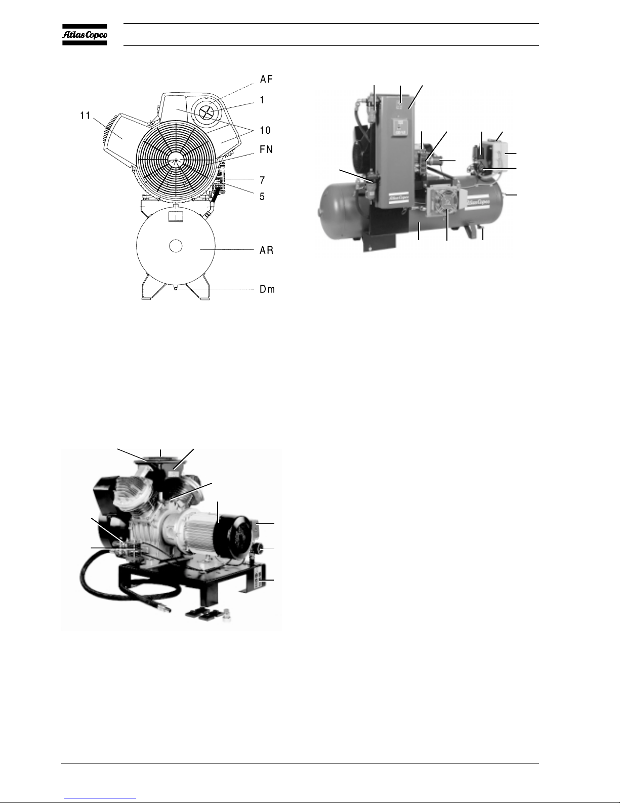
Fig. 1.1 Example of Compressor Block with unloading
valve
Fig. 1.2 Example of Power Pack with unloading valve
Fig. 1.3 Example of Power Pack
AF Air filter
DP Oil drain plug
FN Fan
M Motor
SG Oil level sight-glass
1 Cover
2 Intercooler
3 Air inlet silencer
4 Crankcase
5 Cooling pipe
6 Cylinder
7 Unloader
8 Relief valve
9 HP cylinder
10 LP cylinder
Figs. 1.1 up to 1.3 General views, Compressor Block -
Power Pack
When the pressure in the air receiver reaches the pre-set
maximum pressure, the contacts as well as pressure release
valve (2) are opened. The motor stops, the air at the delivery
side of the compressor is vented to atmosphere and check valve
(CV) closes to prevent venting of the receiver.
When the pressure in the air receiver decreases to the pre-set
minimum pressure, the contacts of the air pressure switch close
and pressure release valve (2) closes. The motor restarts and
compressed air is supplied to the receiver again.
3AF 1
6
8
4
7
5
FN
2
50948F
45
7
FN
2
10
1
AF
3
9
8
M
50949F
M
10 1
AF
3
FN
DP
SG
4
50973F
2920 1257 04
5
Instruction book
Fig. 1.4 Complete Unit, LT15/22, horizontal receiver
(standard receiver is 120l)
Fig. 1.5 Complete Unit, LE/LT15/22/40, vertical receiver
(standard receiver is 250l)
Fig. 1.6 Complete Unit, LE/LT75 60 Hz, LF75 and
LE/LT110-150 (standard receiver is 250l)
AC Air cooler
AF Air filter
AR Air receiver
AV Air outlet valve
CV Check valve
Dm Condensate drain valve
FC Filler cap
FN Fan
Gp Air pressure gauge
M Motor
P1 Hourmeter, running time
SV Safety valve
Y1 Loading solenoid valve
1 Cover
2 Blow-off silencer
3 Air inlet silencer
4 Dewpoint indicator
5 Cooling pipe
6 Electric cabinet
7 Unloader
8 Relief valve
9 Pictograph, switch off voltage and
depressurize before maintenance or repair
10 LP cylinder
11 HP cylinder
12 DD filter
13 Air pressure switch with on/off switches
14 PD filter
15 CD dryer
Figs. 1.4 up to 1.9 General views
10
3
1AF
SV
13
AV
Gp
9
Dm
M
CV
AR
50950F
7
1AF
3
2
M
Y1
13
P1
6
Gp
AV
AR
Dm
50952F
Dm
9
AV
SV
AR
Gp
13
M
8
1
AF
3
50951F
2920 1257 04
6
Instruction book
1.3.2 LE/LT40 up to -150, LF40 up to -75, each with
Y/D starter (Fig. 1.11)
The regulating system includes:
- Electric cubicle (11)
- Air pressure switch (MDR)
- On/off switch (5)
- Solenoid valve (Y1)
- Unloader (UA) with integrated check valve (CV)
Operation
Air pressure switch (MDR) opens and closes its contacts at
pre-set pressures. During loaded operation, the contacts are
closed: the motor is running and solenoid valve (Y1) is
energized preventing the compressed air from flowing to
unloader (UA).
When the pressure in the air receiver reaches the pre-set
maximum pressure, the contacts of pressure switch (MDR)
open. The motor stops and solenoid valve (Y1) is deenergized. Compressed air from the receiver will flow via the
solenoid valve to plunger (12) which causes unloading valve
(UV) to open. The air at the delivery side of the compressor
is blown through silencer (9) to atmosphere and check valve
(CV) closes to prevent venting of the receiver.
When the pressure in the air receiver decreases to the pre-set
minimum pressure, the contacts of the pressure switch close.
The motor restarts and, after switching over from star to delta,
solenoid valve (Y1) is energized. Control air from the unloader
plunger chamber is vented to atmosphere. Unloading valve
(UV) closes and compressed air is supplied to the receiver
again.
Fig. 1.7 Complete Unit, LT75 60 Hz and LT110
Fig. 1.8 Unsilenced pack
Fig. 1.9 LE/LF/L T with CD dryer
AR A C Dm
M
2
7 13
P1
6
Gp
AV
12
4
15
14
50954F
7
SV
AF
1
3
13
Gp
9
FC
M
50953F
D 0656
2920 1257 04
7
Instruction book
Fig. 1.10 Air flow of LE and regulating system of LE/LF/L T15 up to -55 with DOL starter and separate air pressure switch
Fig. 1.11 Air flow of LT and regulating system of LE/LT40 up to -110, LE150 and LF55/75 with Y/D starter and electric
cabinet
2920 1257 04
8
Instruction book
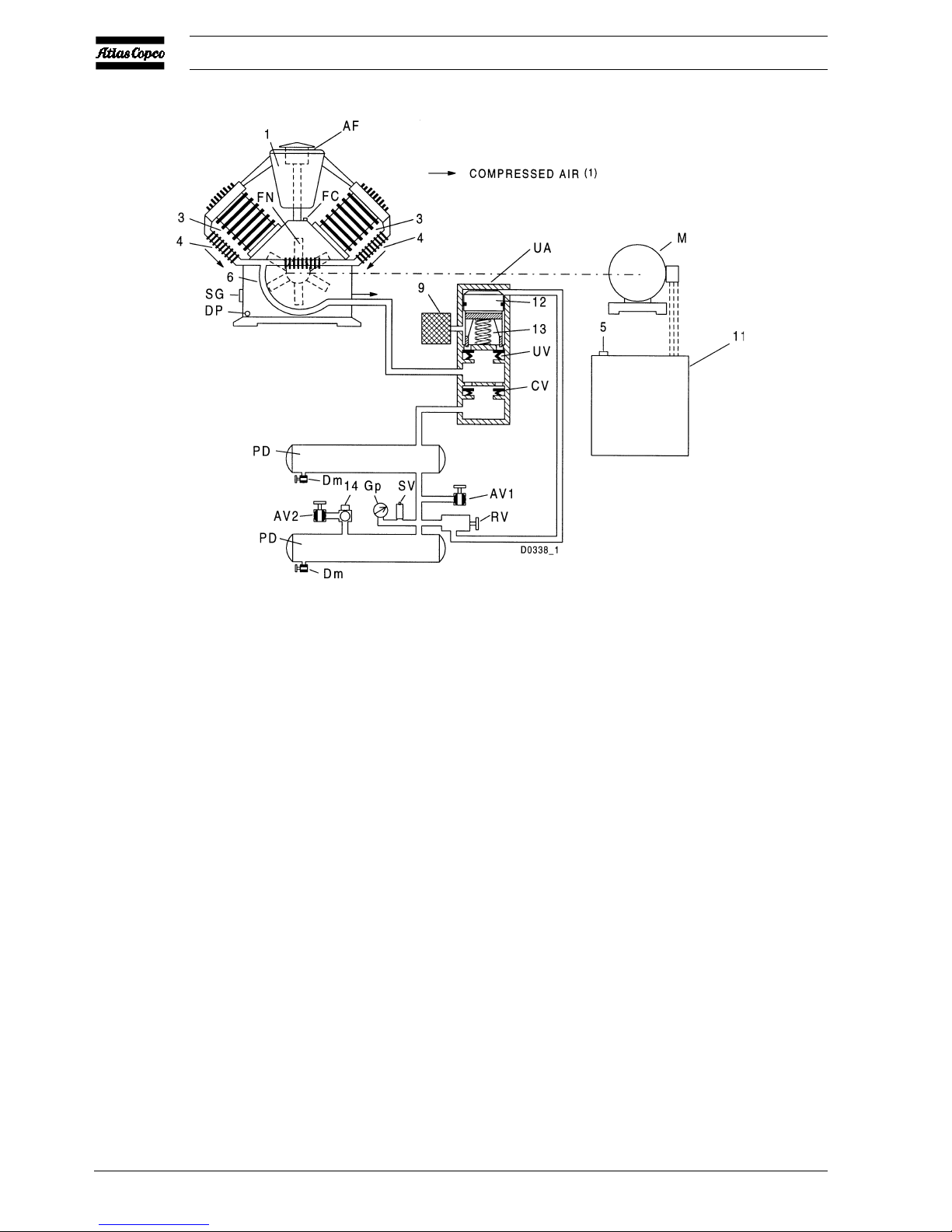
Fig. 1.12 Air flow of LE Trolley and regulating system of LE/LF/LT Trolley
AF Air filter
AR Air receiver
AV Air outlet valve
AV1/2 Air outlet valves
CV Check valve
Dm Condensate drain valve
DP Oil drain plug
FC Oil filler cap
FN Fan
Gp Air pressure gauge
M Motor
MDR Air pressure switch
PD Pulsation damper
R V Pilot valve
SG Oil level sight-glass
SV Safety valve
UA Unloader
UV Unloading valve
Y1 Loading solenoid valve
1 Air inlet silencer
2 Pressure release valve
3 Cylinder
4 Cooler
5 On/off switch
6 Cooling pipe
7 LP cylinder
8 HP cylinder
9 Blow-off silencer
10 Intercooler
11 Electric cabinet
12 Plunger
13 Spring
14 Pressure regulator
Figs. 1.10 up to 1.12 Air flow and regulating systems
1.3.3 LE/LF/LT Trolley (Fig. 1.12)
The regulating system includes:
- Pilot valve (RV)
- Unloader (UA) with integrated check valve (CV)
- Electric cabinet (11) (only on electric motor driven T rolley
compressors)
Operation
Pilot valve (R V) opens and closes at pre-set pressures. During
loaded operation, pilot valve (RV) is closed preventing the
compressed air from flowing to unloader (UA).
When the pressure in the pulsation dampers (PD) reaches the
pre-set maximum pressure, pilot valve (RV) will open.
2920 1257 04
9
Instruction book
Compressed air from the pulsation dampers will flow to
plunger (12) which causes unloading valve (UV) to open. The
air at the delivery side of the compressor is blown through
silencer (9) to atmosphere and check valve (CV) closes to
prevent venting of the pulsation dampers. The compressor
runs unloaded.
When the pressure in the pulsation dampers decreases to the
pre-set minimum pressure, the pilot valve closes. Control air
from the unloader plunger chamber is vented to atmosphere.
Unloading valve (UV) closes and compressed air is supplied
to the pulsation dampers again.
Fig. 1.13 Optional silencing hood
Fig. 1.14 Pack compressor with optional silencing hood
AV Air outlet valve
Dm Condensate drain valve
1 Silencing hood (standard option)
2 Electric cabinet
3 On/off switch
4 Air pressure switch with on/off switches
Figs. 1.13 and 1.14 Pack - silencing hood
Fig. 1.15 LE/LF/LT ETROL
Fig. 1.16 LE/LF/LT PETROL
AF Air filter
AV1 Air outlet valve
Dm Condensate drain
valve
Gp Air pressure gauge
Me Electric motor
Mp Petrol motor
PD Pulsation damper
R V Pilot valve
UA Unloader
1 Lifting yoke
2 Cylinder
3 T owing handle
4 Blow-off silencer
5 Cover
6 Air inlet silencer
7 Fuel tank
Figs. 1.15 and 1.16 LE/LF/LT E Trolley
1
3
2
AV
Dm
50955F
2
4
1
50956F
Mp
7
1
5
AF
6
2
4
PD
Dm
AV1
3
Gp
50958F
RV
65
AF
1
3
Me
4
PD
UA
Dm
50957F
2920 1257 04
10
Instruction book
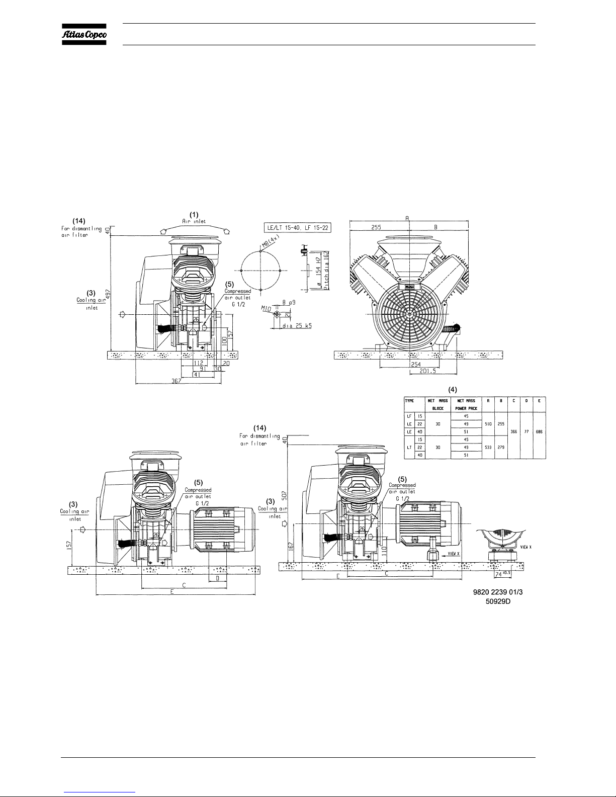
2 Installation and handling
2.1 Dimension drawings
Fig. 2.1 Dimension drawing, LE/LT15 up to -40 and LF15/22 Power Pack
2920 1257 04
11
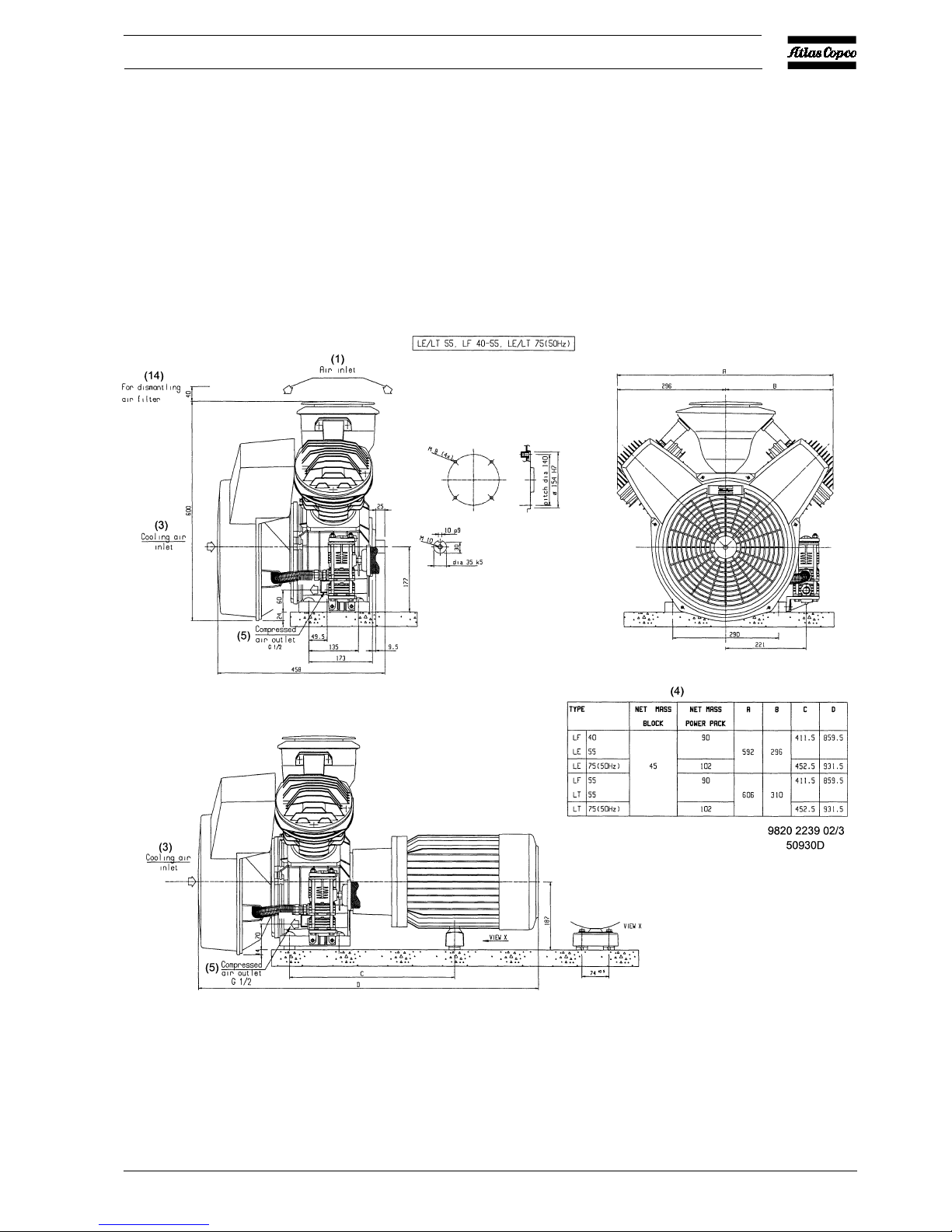
Instruction book
Fig. 2.2 Dimension drawing, LE/LT55/75 and LF40/55 Power Pack
2920 1257 04
12
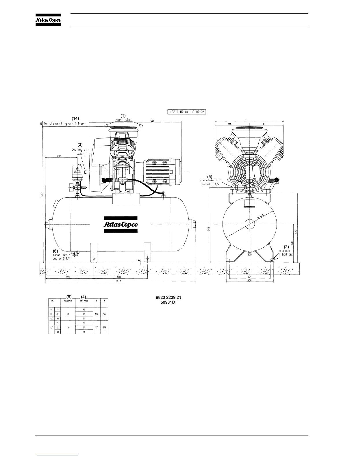
Instruction book
Fig. 2.3 Dimension drawing, LE/LT15 up to -40 and LF15/22 Complete Unit (horizontal 120 l receiver)
2920 1257 04
13
Instruction book
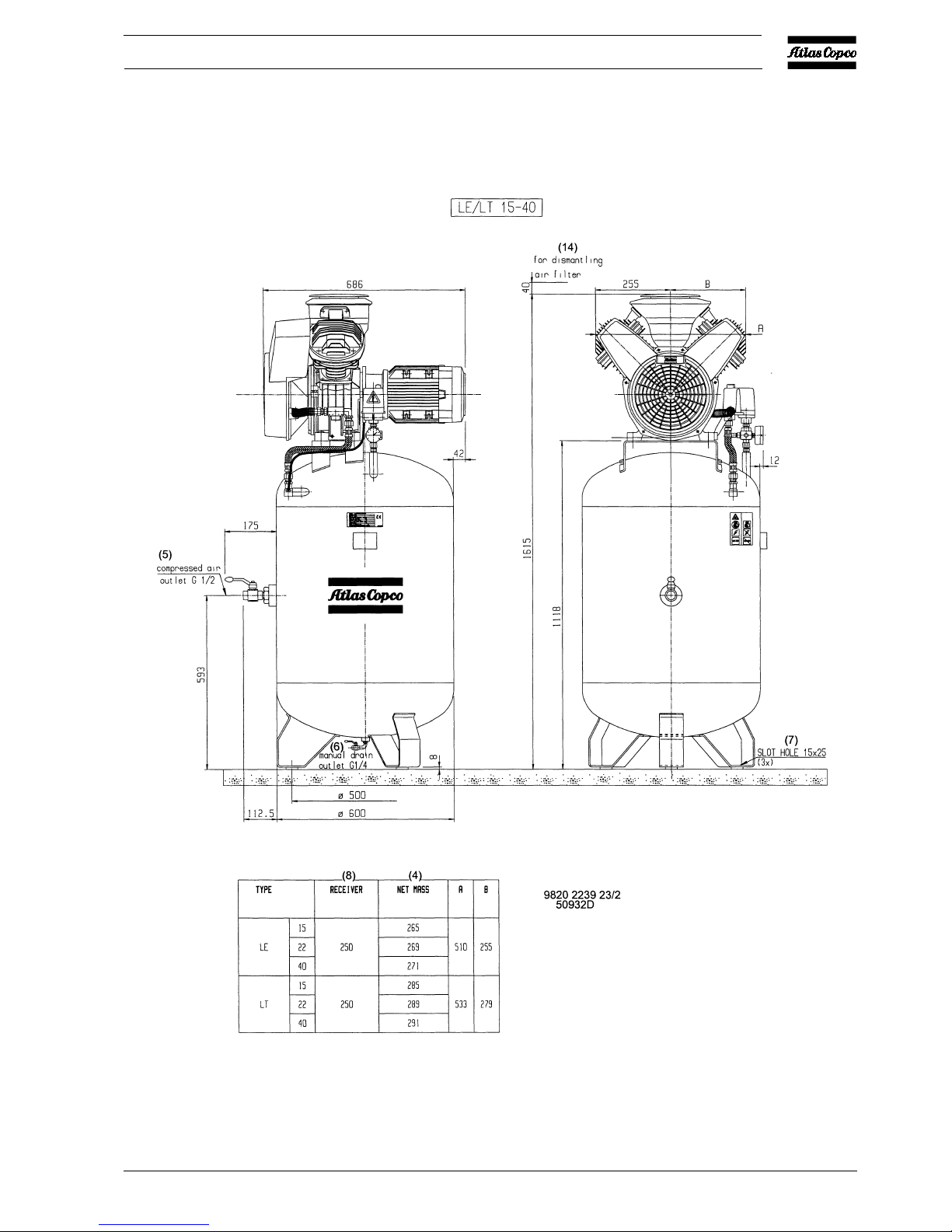
Fig. 2.4 Dimension drawing, LT15 up to -40 Complete Unit (vertical 250 l receiver)
2920 1257 04
14
Instruction book
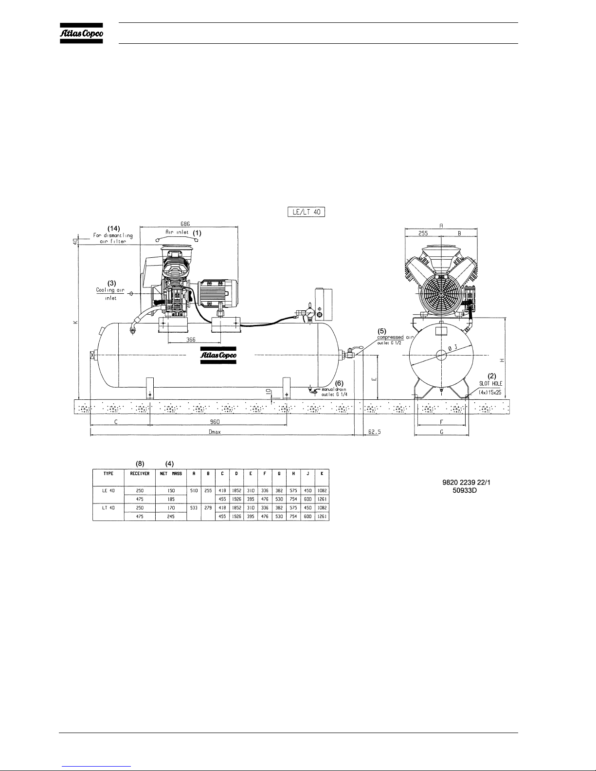
Fig. 2.5 Dimension drawing, LE/LT40 Complete Unit (horizontal 250/475 l receiver)

2920 1257 04
15
Instruction book
Fig. 2.6 Dimension drawing, LE/LT55/75 and LF40/55 Complete Unit (horizontal 250/475 l receiver)
 Loading...