

Atlas Copco GVS 16A, GVS 25A, GVS 40A, GVS 100A, GVS 200A Instruction Book
...
Atlas Copco
Oil-sealed rotary
vane vacuum pumps
GVS 16A, GVS 25A, GVS 40A,
GVS 60A, GVS 100A, GVS 200A,
GVS 300A, GVS 470A, GVS 630A
Instruction Book
6996 0224 30
Issue B


Atlas Copco
Oil-sealed rotary vane vacuum pumps
GVS 16A, GVS 25A, GVS 40A, GVS 60A, GVS 100A,
GVS 200A, GVS 300A, GVS 470A, GVS 630A
Instruction book
Original instructions
2017 - 05
No. 6996 0224 30
www.atlascopco.com
Copyright notice
Any unauthorized use or copying of the contents or any part thereof is prohibited. This applies in
particular to trademarks, model denominations, part numbers and drawings.
This instruction book is valid for CE as well as non-CE labelled machines. It meets the
requirements for instructions specified by the applicable European directives as identified in the
Declaration of Conformity.

Instruction book
4 6996 0224 30

Instruction book
Table of contents
1. Safety precautions ...................................................................................................................................... 7
1.1 Safety icons ................................................................................................................................................... 7
1.2 General precautions ...................................................................................................................................... 7
1.3 Safety precautions during installation ........................................................................................................... 7
1.4 Safety precautions during operation ............................................................................................................. 9
1.5 Safety precautions during maintenance or repair ....................................................................................... 10
2. General description................................................................................................................................... 12
2.1 What is vacuum and how is flow rate understood ....................................................................................... 12
2.2 General description ..................................................................................................................................... 14
2.3 Air flow ......................................................................................................................................................... 15
2.4 Oil flow ......................................................................................................................................................... 21
3. Installation ................................................................................................................................................. 22
3.1 Dimension drawings .................................................................................................................................... 22
3.2 Installation proposal .................................................................................................................................... 30
3.3 Motor installation (if applicable) ................................................................................................................... 40
3.4 Electrical connections ................................................................................................................................. 44
3.5 Pictographs ................................................................................................................................................. 45
4. Operating instructions .............................................................................................................................. 46
4.1 Initial start-up ............................................................................................................................................... 46
4.2 Starting ........................................................................................................................................................ 48
4.3 During operation .......................................................................................................................................... 48
4.4 Stopping ...................................................................................................................................................... 48
4.5 Taking out of operation ............................................................................................................................... 48
5. Maintenance ............................................................................................................................................... 49
5.1 Preventive maintenance schedule .............................................................................................................. 49
5.2 Oil specifications ......................................................................................................................................... 50
5.3 Storage after installation ............................................................................................................................. 50
5.4 Service kits .................................................................................................................................................. 51
5.5 Disposal of used material ............................................................................................................................ 51
6. Adjustments and servicing procedures ................................................................................................. 52
6.1 Drive motor .................................................................................................................................................. 52
6.2 Exhaust filter replacement ........................................................................................................................... 52
6.3 Oil and oil filter change ................................................................................................................................ 54
6.4 Cleaning radiator, motor fan guard and pump ............................................................................................ 55
6.5 Cleaning the intake filter (optional) element ................................................................................................ 55
6.6 Replacing V - belts ...................................................................................................................................... 55
6996 0224 30 5

Instruction book
6.7 V-belt tensioning .......................................................................................................................................... 57
7. Problem solving ........................................................................................................................................ 58
8. Technical data ........................................................................................................................................... 59
8.1 Reference conditions and limitations .......................................................................................................... 59
8.2 Pump data ................................................................................................................................................... 62
8.3 Motor data ................................................................................................................................................... 67
9. Declaration of conformity ......................................................................................................................... 69
6 6996 0224 30
Instruction book
Danger for life
Warning
Important note
If the machine is equipped with an automatic restart after voltage failure function and
if this function is active, be aware that the machine will restart automatically when the
power is restored if it was running when the power was interrupted!
All responsibility for any damage or injury resulting from neglecting these precautions,
or non observance of the normal caution and care required for installation, operation,
maintenance and repair, even if not expressly stated, will be disclaimed by the
manufacturer.
1. Safety precautions
1.1 Safety icons
Explanation
1.2 General precautions
1. The operator must employ safe working practices and observe all related work safety requirements
and regulations.
2. If any of the following statements does not comply with the applicable legislation, the stricter of the two
shall apply.
3. Installation, operation, maintenance and repair work must only be performed by authorized, trained,
specialized personnel.
4. The vacuum pump is designed for handling atmospheric air only. No other gases, vapours or fumes
should be exposed to the vacuum pump intake or processed by the vacuum pump.
5. Before any maintenance, repair work, adjustment or any other non-routine checks, stop the vacuum
pump, press the emergency stop button, switch off the voltage and make sure that the pump system is
at atmospheric pressure level. In addition, the power isolating switch must be opened and locked.
6. Avoid contact with pump intake during operation.
7. The owner is responsible for maintaining the unit in safe operating condition. Parts and accessories
shall be replaced if unsuitable for safe operation.
8. It is not allowed to walk or stand on the unit or on its components.
1.3 Safety precautions during installation
6996 0224 30 7

Precautions during installation
1. The machine must only be lifted using suitable equipment in accordance with the applicable safety
regulations. Loose or pivoting parts must be securely fastened before lifting. It is strictly forbidden to
dwell or stay in the risk zone under a lifted load. Lifting acceleration and deceleration must be kept
within safe limits. Wear a safety helmet when working in the area of overhead or lifting equipment.
2. The unit is designed for indoor use. If the unit is installed outdoors, special precautions must be taken;
consult your supplier.
3. Place the machine where the ambient air is as cool and clean as possible. If necessary, install a
suction duct. Never obstruct the air inlet. Water handling capacity is limited.
4. Any blanking flanges, plugs, caps and desiccant bags must be removed before connecting the pipes.
5. Air hoses must be of correct size and suitable for the working pressure. Never use frayed, damaged or
worn hoses. Distribution pipes and connections must be of the correct size and suitable for the working
pressure.
6. The aspirated air must be free of flammable fumes, vapours and particles, e.g. paint solvents that can
lead to internal fire or explosion.
7. Arrange the air intake so that loose clothing worn by people cannot be sucked in.
8. No external force may be exerted on the inlet and outlet connections; the connected pipes must be free
of strain.
Instruction book
9. If remote control is installed, the machine must bear a clear sign stating: DANGER: This machine is
remotely controlled and may start without warning.
The operator has to make sure that the machine is stopped, depressurized and that the electrical
isolating switch is open, locked and labelled with a temporary warning before any maintenance or
repair. As a further safeguard, persons switching remotely controlled machines shall take adequate
precautions to ensure that there is no one checking or working on the machine. To this end, a suitable
notice shall be affixed to the start equipment.
10. Air-cooled machines must be installed in such a way that an adequate flow of cooling air is available
and that the exhausted air does not recirculate to the inlet.
11. The electrical connections must correspond to the applicable codes. The machines must be earthed
and protected against short circuits by fuses in all phases. A lockable power isolating switch must be
installed near the pump.
12. On machines with automatic start/stop system or if the automatic restart function after voltage failure is
activated, a sign stating "This machine may start without warning" must be affixed near the instrument
panel.
13. In multiple vacuum pump systems, manual valves must be installed to isolate each pump. Non-return
valves (check valves) must not be relied upon for isolating multiple systems.
14. Never remove or tamper with the safety devices, guards or insulation fitted on the machine.
15. Piping or other parts with a temperature in excess of 70˚C (158˚F) and which may be accidentally
touched by personnel in normal operation must be guarded or insulated. Other high temperature piping
must be clearly marked.
16. For water-cooled machines, the cooling water system installed outside the machine has to be
protected by a safety device with set pressure according to the maximum cooling water inlet pressure.
17. If the ground is not level or can be subject to variable inclination, consult the manufacturer.
18. Pump outlet air contains traces of oil mist. Ensure compatibility with the working environment.
19. Whenever air containing hazardous substances is sucked in (i.e. biological or microbiological agents),
use abatement systems placed upstream of the vacuum pump.
20. Any vacuum pump placed in an application with inlet gas stream temperatures above the published
maximum temperature should be approved by Atlas Copco prior to start-up.
8 6996 0224 30
Instruction book
Also consult sections Safety precautions during operation and Safety precautions
during maintenance or repair.
These precautions apply to machinery processing or consuming air or inert gas.
Processing of any other gas requires additional safety precautions typical to the
application which are not included herein.
Some precautions are general and cover several machine types and equipment;
hence some statements may not apply to your machine.
All responsibility for any damage or injury resulting from neglecting these precautions,
or non observance of the normal caution and care required for installation, operation,
maintenance and repair, even if not expressly stated, will be disclaimed by the
manufacturer.
Some precautions are general and cover several machine types and equipment;
hence some statements may not apply to your machine.
1.4 Safety precautions during operation
Precautions during operation
1. Never touch any piping or components of the vacuum pump during operation.
2. Use only the correct type and size of hose end fittings and connections. Make sure that a hose is fully
depressurized before disconnecting it.
3. Persons switching on remotely controlled machines shall take adequate precautions to ensure that
there is no one checking or working on the machine. To this end, a suitable notice shall be affixed to
the remote start equipment.
4. Never operate the machine when there is a possibility of taking in flammable or toxic fumes, vapours or
particles.
5. Never operate the machine below or in excess of its limit ratings.
6. Keep all bodywork doors shut during operation. The doors may be opened for short periods only, e.g.
to carry out routine checks. Wear ear protectors when opening a door.
On vacuum pumps without bodywork, wear ear protection in the vicinity of the machine.
7. People staying in environments or rooms where the sound pressure level reaches or exceeds 80 dB(A)
shall wear ear protectors.
8. Periodically check that:
All guards are in place and securely fastened
All hoses and/or pipes inside the machine are in good condition, secure and not rubbing
There are no leaks
All fasteners are tight
All electrical leads are secure and in good order
Safety valves and other pressure relief devices are not obstructed by dirt or paint
Air outlet valve and air net, i.e. pipes, couplings, manifolds, valves, hoses, etc. are in good repair,
free of wear or abuse
6996 0224 30 9
Electrical cabinet air cooling filters are not clogged
9. If warm cooling air from vacuum pumps is used in air heating systems, e.g. to warm up a workroom,
take precautions against air pollution and possible contamination of the breathing air.
10. On water-cooled vacuum pumps using open circuit cooling towers, protective measures must be taken
to avoid the growth of harmful bacteria such as Legionella pneumophila bacteria.
Also consult sections Safety precautions during installation and Safety precautions

during maintenance or repair. These precautions apply to machinery processing or
consuming air or inert gas. Processing of any other gas requires additional safety
precautions typical to the application which are not included herein.
Some precautions are general and cover several machine types and equipment;
hence some statements may not apply to your machine.
All responsibility for any damage or injury resulting from neglecting these precautions,
or non observance of the normal caution and care required for installation, operation,
maintenance and repair, even if not expressly stated, will be disclaimed by the
manufacturer.
11. Do not remove any of, or tamper with, the sound-damping material.
12. Never remove or tamper with the safety devices, guards or insulations fitted on the machine.
13. The oil separator tank can be slightly pressurised. Do not open and do not leave oil filler or drain plugs
open during operation.
14. Do not use the pump as a compressor.
15. Never run the pump without the air intake filter mounted.
1.5 Safety precautions during maintenance or repair
Instruction book
Precautions during maintenance or repair
1. Always use the correct safety equipment (such as safety glasses, gloves, safety shoes, etc.).
2. Use only the correct tools for maintenance and repair work.
3. Use only genuine spare parts.
4. All maintenance work shall only be undertaken when the machine has cooled down.
5. A warning sign bearing a legend such as "Work in progress; do not start" shall be attached to the
starting equipment.
6. Persons switching on remotely controlled machines shall take adequate precautions to ensure that
there is no one checking or working on the machine. To this end, a suitable notice shall be affixed to
the remote start equipment.
7. Before removing any component, effectively isolate the machine from all sources of under- and/or
overpressure and make sure that the pump system is at atmospheric pressure level.
8. Never use flammable solvents or carbon tetrachloride for cleaning parts. Take safety precautions
against toxic vapours of cleaning liquids.
9. Scrupulously observe cleanliness during maintenance and repair. Keep dirt away by covering the parts
and exposed openings with a clean cloth, paper or tape.
10. Never weld or perform any operation involving heat near the oil system. Oil tanks must be completely
purged, e.g. by steam cleaning, before carrying out such operations. Never weld on, or in any way
modify, pressure vessels.
11. Whenever there is an indication or any suspicion that an internal part of a machine is overheated, the
machine shall be stopped but no inspection covers shall be opened before sufficient cooling time has
elapsed; this to avoid the risk of spontaneous ignition of the oil vapour when air is admitted.
12. Never use a light source with open flame for inspecting the interior of a machine, pressure vessel, etc.
13. Make sure that no tools, loose parts or rags are left in or on the machine.
14. All regulating and safety devices shall be maintained with due care to ensure that they function
properly. They may not be put out of action.
10 6996 0224 30
15. Before clearing the machine for use after maintenance or overhaul, check that operating pressures,
Instruction book
Also consult sections Safety precautions during installation and Safety precautions
during operation.
These precautions apply to machinery processing or consuming air or inert gas.
Processing of any other gas requires additional safety precautions typical to the
application which are not included herein.
Some precautions are general and cover several machine types and equipment;
hence some statements may not apply to your machine.
Some precautions are general and cover several machine types and equipment;
hence some statements may not apply to your machine.
temperatures and time settings are correct. Check that all control and shut-down devices are fitted and
that they function correctly. If removed, check that the coupling guard of the vacuum pump drive shaft
has been reinstalled.
16. Every time the separator element is renewed, examine the discharge and the inside of the oil separator
vessel for carbon deposits; if excessive, the deposits should be removed.
17. Protect the motor, air filter, electrical and regulating components, etc. to prevent moisture from entering
them, e.g. when steam cleaning.
18. Make sure that all sound damping material and vibration dampers, e.g. damping material on the
bodywork and in the air inlet and outlet systems of the vacuum pump are in good condition. If
damaged, replace it by genuine material from the manufacturer to prevent the sound pressure level
from increasing.
19. Never use caustic solvents which can damage materials of the air net, e.g. polycarbonate bowls.
20. Faults or wearing of seals may cause oil lubricant leaks. Avoid dispersion in soil and pollution of other
materials.
6996 0224 30 11
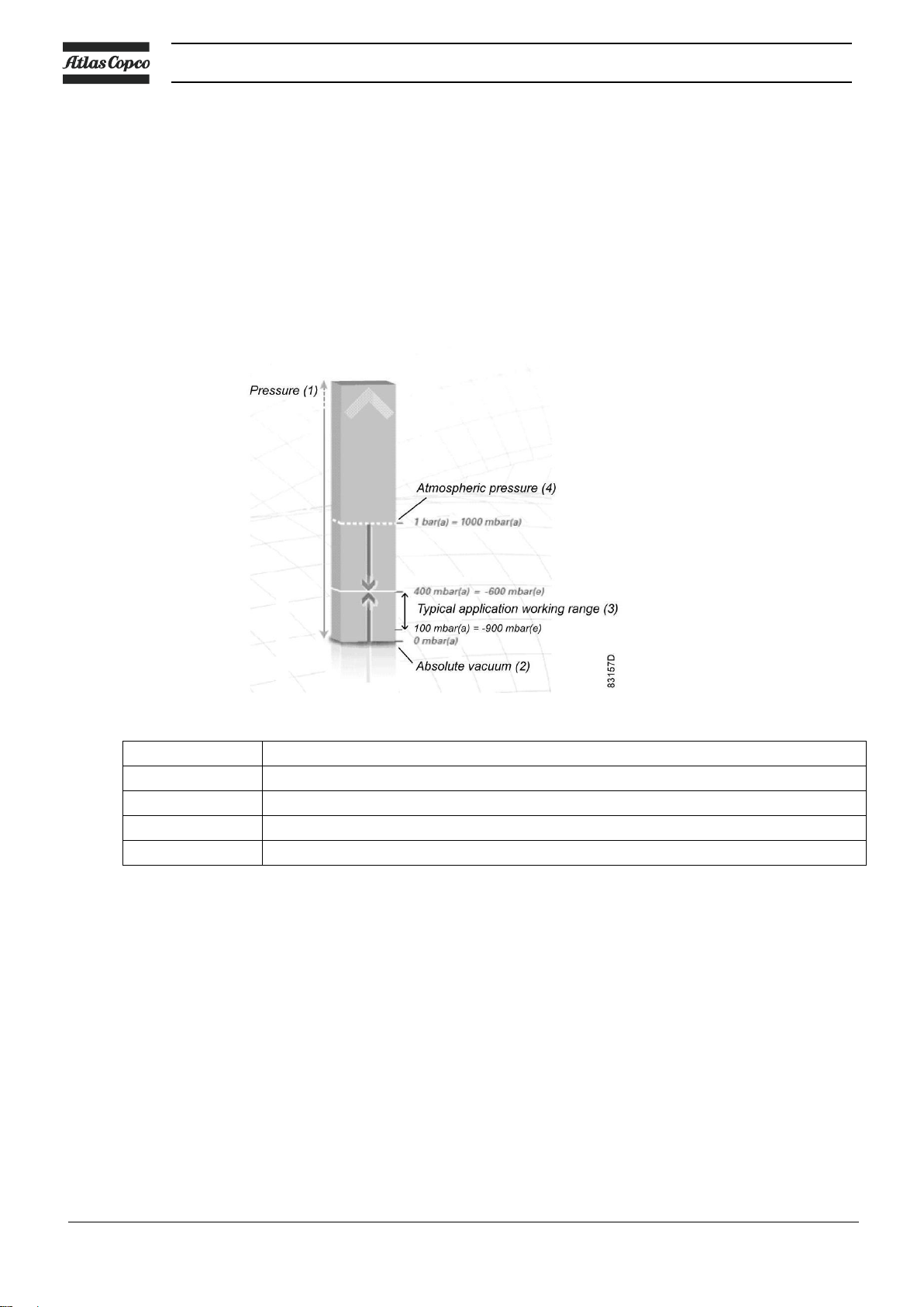
Reference
Designation
1
Pressure
2
Absolute vacuum
3
Typical application working range
4
Atmospheric pressure
2. General description
2.1 What is vacuum and how is flow rate understood
What is vacuum and how to denote
A vacuum is any pressure in a system that is below the ambient atmospheric pressure. It can be denoted
in absolute terms or in effective (gauge) terms:
mbar(a) – absolute pressure – denotes how much the pressure is above absolute zero vacuum.
(minus) mbar(e) – the effective or gauge pressure – denotes how much the pressure is below the local
atmospheric pressure.
Instruction book
Atmospheric pressure at sea level is roughly 1 bar(a) or 1000 mbar(a) or 0 bar(e). The typical working
range for pump applications is 400 mbar(a) to 100 mbar(a), i.e. -600 mbar(e) to -900 mbar(e). This
operating pressure range is just indicative. The GVS A vacuum pumps are designed for continuous
operation between atmospheric pressure and their ultimate pressure.
It is important to understand which type of reference is required before selecting a pressure instrument
for measuring the vacuum.
It must be noted that the distinction doesn’t matter for a pressure difference (e.g. pressure loss), since
it is always the result of subtracting 2 pressures (whether stated as absolute or as effective pressures).
12 6996 0224 30

Instruction book
Flow rate definitions
There are 2 common but different ways to denote flow rate in vacuum. The first one is based on the
displacement or volumetric flow rate and the second one is based on the throughput or mass flow rate.
Atlas Copco vacuum pumps use volumetric flow rate to denote performance, the unit being actual m³/h.
Displacement/volumetric flow rate
Over the relevant pressure range, a GVS A pump operates at constant motor speed (rotations per minute)
and since the compression chambers have fixed dimensions, the same volume of air is pumped from inlet
to outlet with falling pressure level. Over the relevant pressure range, this makes the volumetric flow rate
practically independent of the vacuum level. It is the expression of the flow rate inside the piping at the
governing vacuum level (in actual m³/h) and is always higher than the standard flow rate (in Nm³/h).
Standard flow rate
Although the volumetric flow rate remains practically constant with decreasing (absolute) pressure, the
number of molecules in that pumped volume is not. By definition: the deeper the vacuum, the lower the
amount of molecules in the same volume. This means that the mass flow will decrease with decreasing
(absolute) pressure. It is clear that a flow rate must be stated at a certain vacuum level when using this
denotation.
6996 0224 30 13
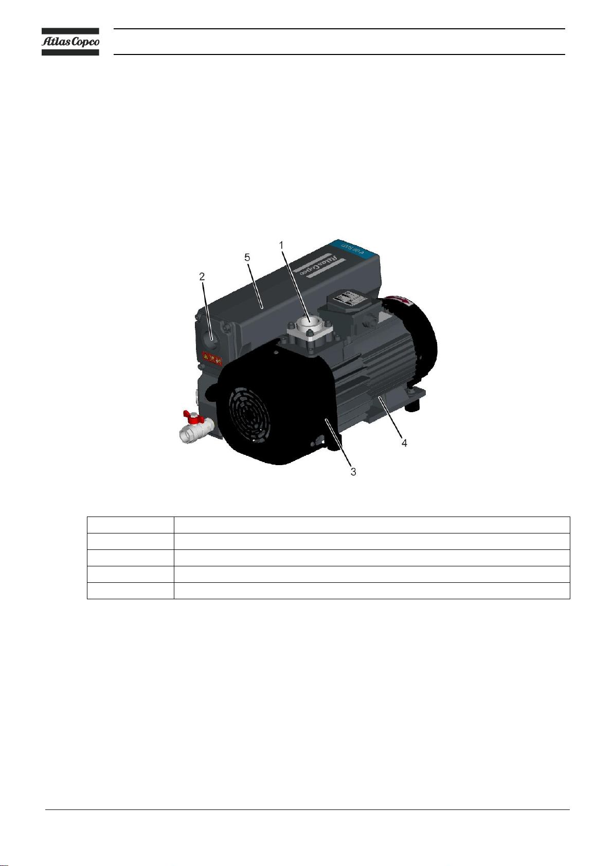
1
Air intake
2
Air outlet
3
Rotary vane element housing
4
Motor
5
Exhaust filter element housing
2.2 General description
The GVS 16A up to GVS 630A are single-stage, oil-sealed and air-cooled rotary vane vacuum pumps
driven by an electric motor. GVS 100A up to GVS 300A are also available without electric motor.
GVS 470A and GVS 630A are belt driven.
The pumps have been specifically designed to work with clean air, inert gas or small amounts of water
vapour. The ambient temperature shall be between 12 °C and 40 °C.
For applications with high oxygen concentration, O2 - versions are available (GVS 60A up to GVS 630A)
Note: lower temperatures are possible with reduced viscosity oil. This temperature range is defined by
Pneurop for performance conformity testing, but 8 °C is the critical point from the motor starting view point.
Instruction book
GVS 60A
14 6996 0224 30
Instruction book
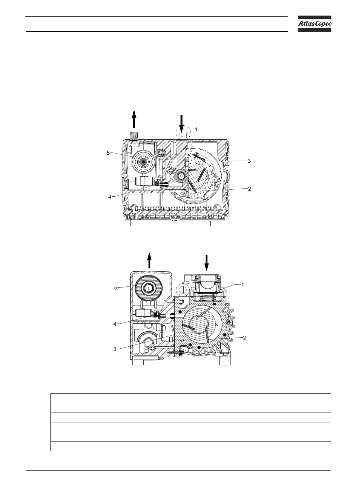
Reference
Designation
1
Inlet non-return valve
2
Vane (vacuum pump element)
3
Exhaust valve
4
Oil recovery valve
5
Exhaust filter element
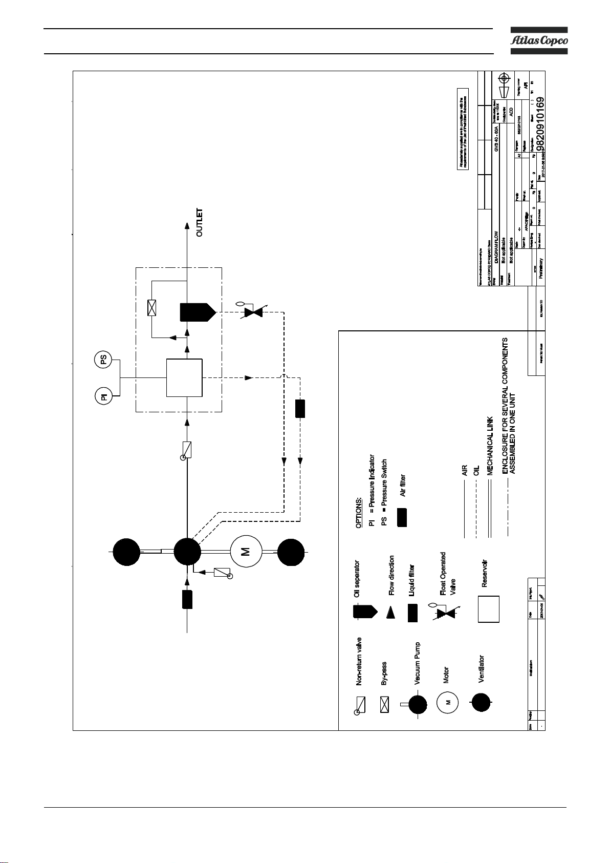
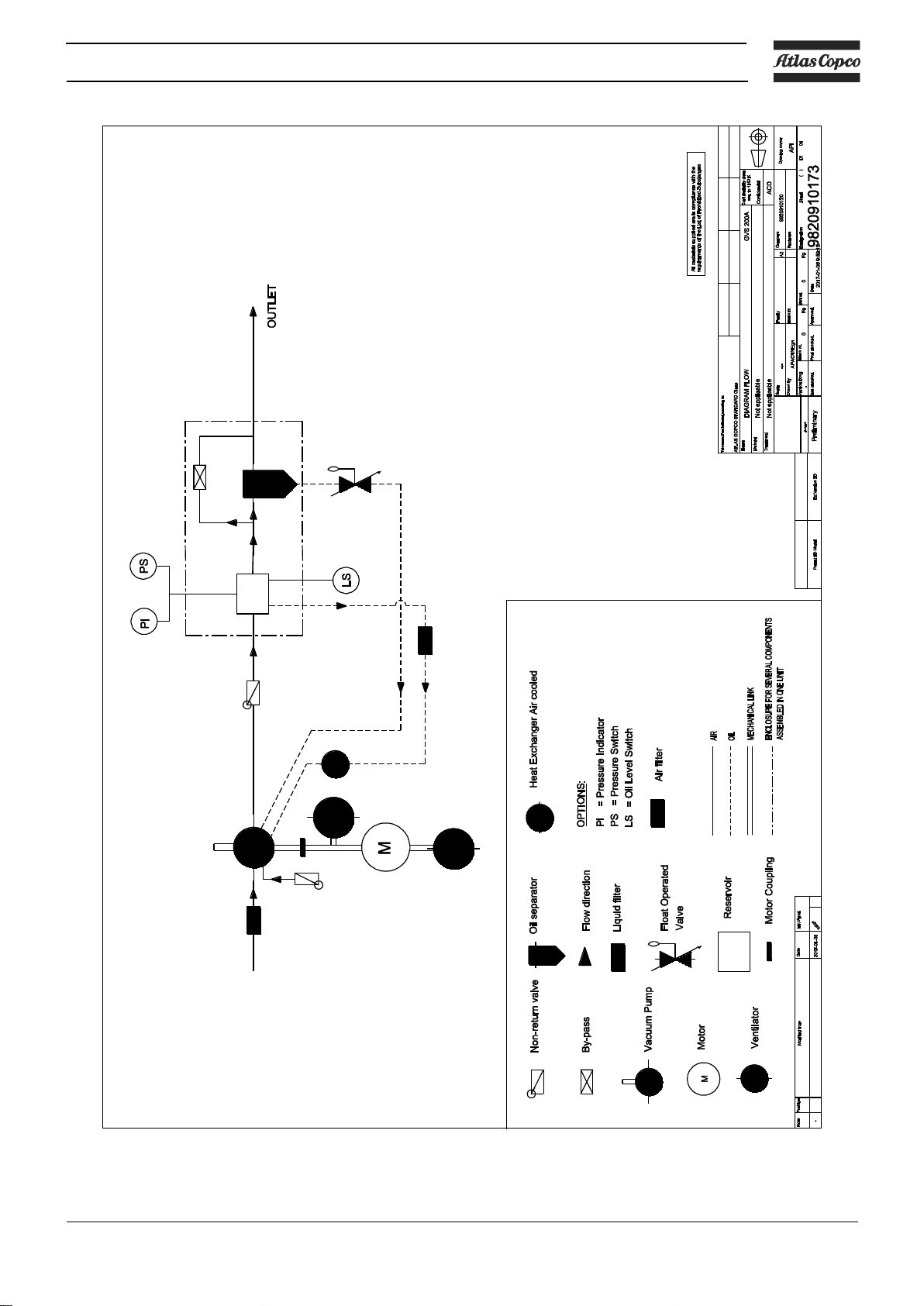
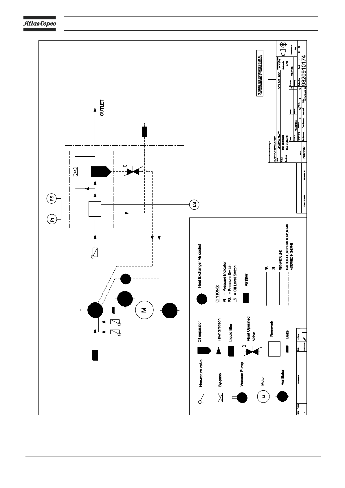
2.3 Air flow
Air drawn through the air intake filter (optional), the inlet protection screen and the inlet non-return
valve is displaced by the vacuum pump element towards the air end exhaust valve. This valve ejects a
mixture of air and oil into the exhaust filter element. After passing the exhaust filter element, clean air conditioned to a few parts per million - is discharged through the outlet.
The vacuum pump is driven by an electric motor.
GVS 16 – 25A
GVS 40-300A
6996 0224 30 15
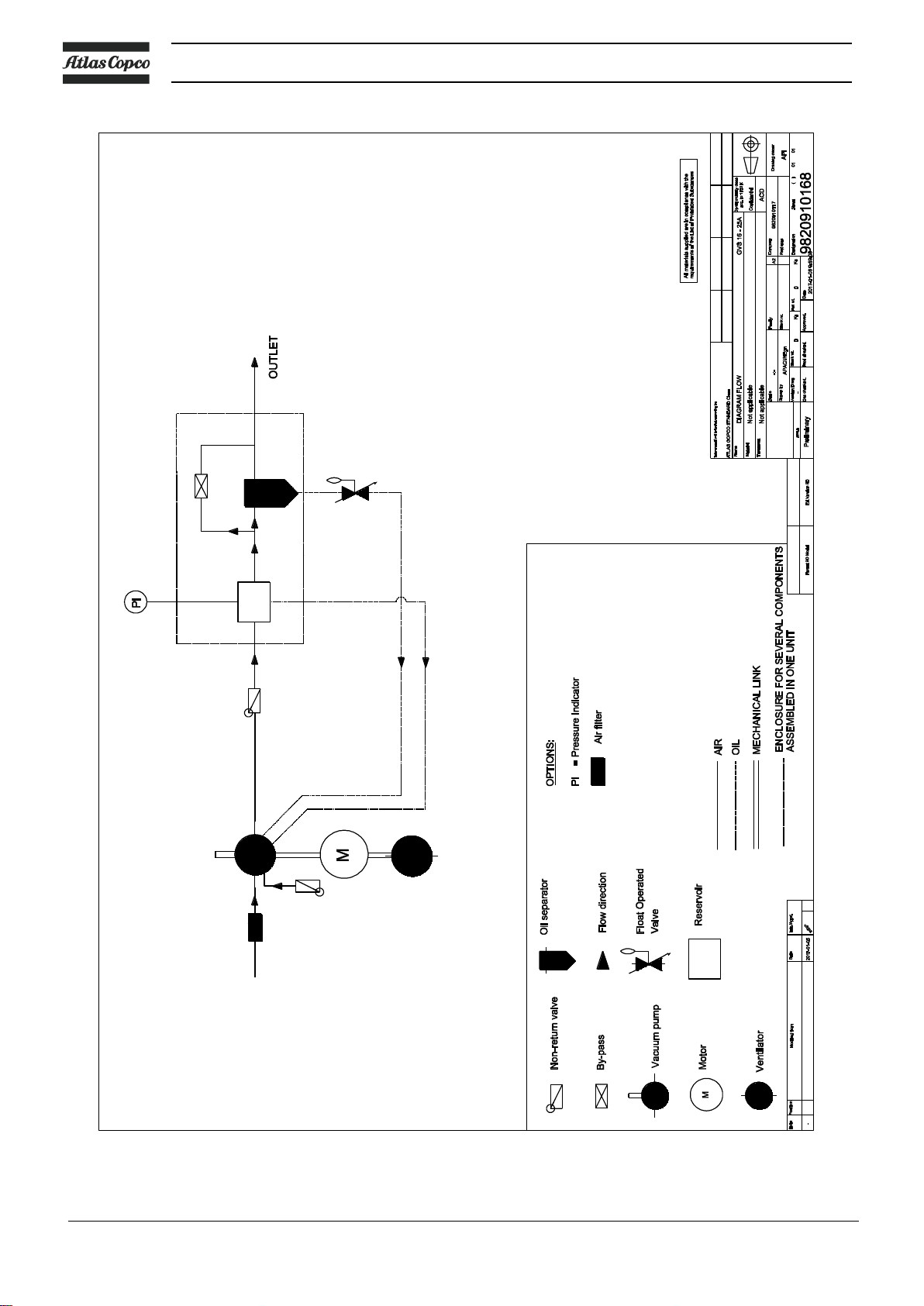
Flow diagram
Instruction book
Flow diagram, GVS 16A and GVS 25A
16 6996 0224 30
Instruction book
Flow diagram, GVS 40A and GVS 60A
6996 0224 30 17

Instruction book
Flow diagram, GVS 100A and GVS 300A
18 6996 0224 30
Instruction book
Flow diagram, GVS 200A
6996 0224 30 19
Instruction book
Flow diagram, GVS 470A and GVS 630A
20 6996 0224 30

Instruction book
2.4 Oil flow
Oil injected into the pump chamber serves to seal, lubricate and cool the pump. The oil entrained with the
compressed gas is coarsely trapped in the bottom part of the oil casing. Then fine filtering occurs in the
integrated exhaust filter elements. The proportion of oil in the exhaust gas is thus reduced below the
visibility threshold (over 99 % entrapment rate). The oil trapped in the exhaust filters is returned to the
generator via an oil return line. To prevent gas flowing at atmospheric pressure from the oil reservoir into
the intake port, the oil return line is controlled by a float valve. The oil cycle is maintained by the pressure
difference existing between the oil casing (pressure above atmospheric pressure) and the intake port
(pressure below atmospheric pressure).
6996 0224 30 21
3. Installation
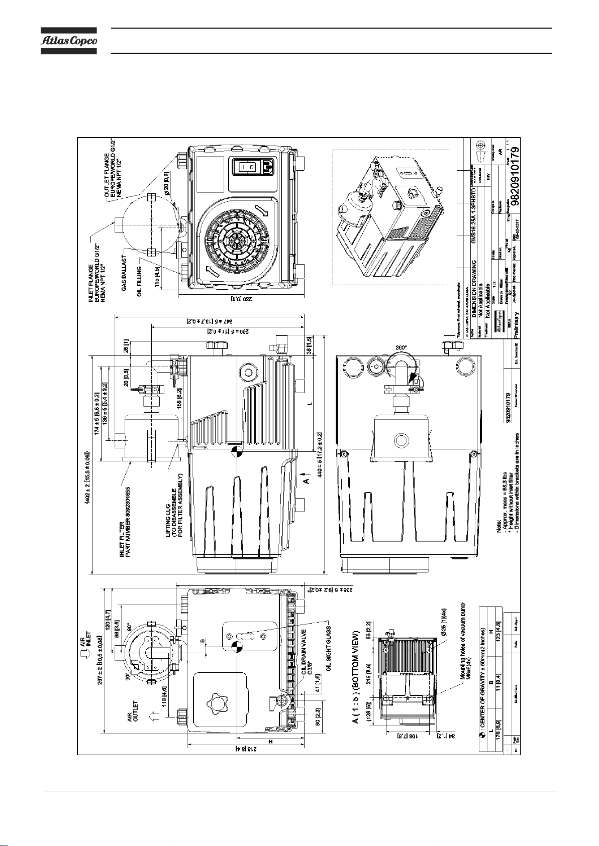
3.1 Dimension drawings
Instruction book
Dimension drawing GVS 16A and GVS 25A
22 6996 0224 30
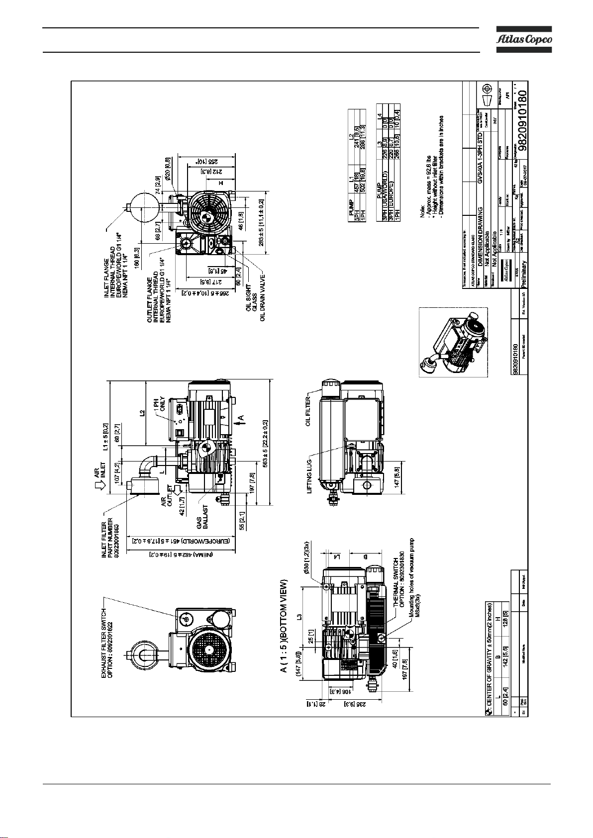
Instruction book
Dimension drawing GVS 40A
6996 0224 30 23
 Loading...