

Atlas Copco GA 5, GA 7, GA 11 Instruction Book
Atlas Copco
Oil-injected rotary screw compressors
GA 5, GA 7, GA 11
Instruction book


Atlas Copco
Oil-injected rotary screw compressors
GA 5, GA 7, GA 11
From following serial No. onwards: CAI 700 000
Instruction book
Original instructions
2009 - 12
Copyright notice
Any unauthorized use or copying of the contents or any part thereof is prohibited.
This applies in particular to trademarks, model denominations, part numbers and drawings.
This instruction book is valid for CE as well as non-CE labelled machines. It meets the
requirements for instructions specified by the applicable European directives as identified
in the Declaration of Conformity.
No. 2920 7090 51
Replaces No. 2920 7090 50
www.atlascopco.com

Instruction book
Table of contents
1 Safety precautions..........................................................................................................7
1.1 SAFETY ICONS...................................................................................................................................7
1.2 SAFETY PRECAUTIONS, GENERAL...........................................................................................................7
1.3 SAFETY PRECAUTIONS DURING INSTALLATION...........................................................................................7
1.4 SAFETY PRECAUTIONS DURING OPERATION..............................................................................................9
1.5 SAFETY PRECAUTIONS DURING MAINTENANCE OR REPAIR.........................................................................10
2 General description......................................................................................................12
2.1 INTRODUCTION.................................................................................................................................12
2.2 AIR FLOW.......................................................................................................................................16
2.3 OIL SYSTEM....................................................................................................................................17
2.4 COOLING SYSTEM.............................................................................................................................18
2.5 CONDENSATE SYSTEM.......................................................................................................................19
2.6 REGULATING SYSTEM........................................................................................................................20
2.7 ELECTRICAL SYSTEM.........................................................................................................................20
2.8 ELECTRICAL DIAGRAMS......................................................................................................................21
2.9 AIR DRYER......................................................................................................................................24
3 Elektronikon® controller..............................................................................................26
3.1
3.2 CONTROL PANEL..............................................................................................................................27
3.3 ICONS USED ON THE DISPLAY..............................................................................................................28
ELEKTRONIKON® REGULATOR.............................................................................................................26
3.4 MAIN SCREEN..................................................................................................................................30
3.5 SHUT-DOWN WARNING.......................................................................................................................30
3.6 SHUT-DOWN....................................................................................................................................32
3.7 SERVICE WARNING............................................................................................................................33
3.8 SCROLLING THROUGH ALL SCREENS.....................................................................................................35
3.9 CALLING UP OUTLET AND DEWPOINT TEMPERATURES...............................................................................38
2 2920 7090 51

Instruction book
3.10 CALLING UP RUNNING HOURS..............................................................................................................39
3.11 CALLING UP MOTOR STARTS...............................................................................................................40
3.12 CALLING UP MODULE HOURS...............................................................................................................41
3.13 CALLING UP LOADING HOURS..............................................................................................................41
3.14 CALLING UP LOAD RELAY...................................................................................................................41
3.15 CALLING UP/RESETTING THE SERVICE TIMER .........................................................................................42
3.16 SELECTION BETWEEN LOCAL, REMOTE OR LAN CONTROL........................................................................43
3.17 CALLING UP/MODIFYING CAN ADDRESS CONTROL..................................................................................43
3.18 CALLING UP/MODIFYING IP, GATEWAY AND SUBNETMASK........................................................................45
3.19 CALLING UP/MODIFYING PRESSURE BAND SETTINGS.................................................................................47
3.20 MODIFYING THE PRESSURE BAND SELECTION.........................................................................................48
3.21 CALLING UP/MODIFYING SERVICE TIMER SETTINGS...................................................................................49
3.22 CALLING UP/MODIFYING THE UNIT OF TEMPERATURE................................................................................49
3.23 CALLING UP/MODIFYING UNIT OF PRESSURE...........................................................................................50
3.24 ACTIVATING AUTOMATIC RESTART AFTER VOLTAGE FAILURE......................................................................50
3.25 SELECTION BETWEEN Y-D OR DOL STARTING......................................................................................50
3.26 CALLING UP MODIFYING LOAD DELAY TIME.............................................................................................51
3.27 CALLING UP MODIFYING MINIMUM STOP TIME..........................................................................................51
3.28 ACTIVATING PASSWORD PROTECTION...................................................................................................52
3.29 ACTIVATE LOAD/UNLOAD REMOTE PRESSURE SENSING.............................................................................52
3.30 CALLING UP/MODIFYING PROTECTION SETTINGS......................................................................................53
3.31 TEST SCREENS................................................................................................................................55
3.32 WEB SERVER..................................................................................................................................56
3.33 PROGRAMMABLE SETTINGS.................................................................................................................64
4 Elektronikon® Graphic controller...............................................................................68
4.1
4.2 CONTROL PANEL..............................................................................................................................70
4.3 ICONS USED....................................................................................................................................71
4.4 MAIN SCREEN..................................................................................................................................74
2920 7090 51 3
ELEKTRONIKON® GRAPHIC CONTROLLER...............................................................................................68

Instruction book
4.5 CALLING UP MENUS..........................................................................................................................76
4.6 INPUTS MENU...................................................................................................................................77
4.7 OUTPUTS MENU...............................................................................................................................78
4.8 COUNTERS......................................................................................................................................80
4.9 SERVICE MENU................................................................................................................................81
4.10 SETPOINT MENU...............................................................................................................................85
4.11 EVENT HISTORY MENU.......................................................................................................................87
4.12 MODIFYING GENERAL SETTINGS...........................................................................................................88
4.13 INFO MENU......................................................................................................................................89
4.14 WEEK TIMER MENU...........................................................................................................................90
4.15 TEST MENU.....................................................................................................................................99
4.16 USER PASSWORD MENU...................................................................................................................100
4.17 WEB SERVER................................................................................................................................101
4.18 PROGRAMMABLE SETTINGS...............................................................................................................109
5 OSD oil/condensate separator (optional).................................................................113
5.1 OSD UNIT....................................................................................................................................113
5.2 OPERATING AND MAINTENANCE INSTRUCTIONS.....................................................................................114
5.3 PICTOGRAPHS...............................................................................................................................115
6 Installation...................................................................................................................117
6.1 DIMENSION DRAWINGS.....................................................................................................................117
6.2 INSTALLATION PROPOSAL.................................................................................................................123
6.3 ELECTRICAL CONNECTIONS...............................................................................................................126
6.4 PICTOGRAPHS...............................................................................................................................131
7 Operating instructions...............................................................................................133
7.1 INITIAL START-UP............................................................................................................................133
7.2 BEFORE STARTING..........................................................................................................................135
7.3 STARTING ....................................................................................................................................136
4 2920 7090 51

Instruction book
7.4 DURING OPERATION........................................................................................................................137
7.5 CHECKING THE DISPLAY...................................................................................................................139
7.6 STOPPING ....................................................................................................................................140
7.7 TAKING OUT OF OPERATION..............................................................................................................141
8 Maintenance................................................................................................................143
8.1 PREVENTIVE MAINTENANCE SCHEDULE................................................................................................143
8.2 OIL SPECIFICATIONS........................................................................................................................146
8.3 STORAGE AFTER INSTALLATION.........................................................................................................146
8.4 SERVICE KITS................................................................................................................................147
8.5 DISPOSAL OF USED MATERIAL...........................................................................................................147
9 Adjustments and servicing procedures...................................................................148
9.1 DRIVE MOTOR ...............................................................................................................................148
9.2 AIR FILTER....................................................................................................................................148
9.3 OIL AND OIL FILTER CHANGE.............................................................................................................149
9.4 OIL SEPARATOR CHANGE.................................................................................................................150
9.5 COOLERS.....................................................................................................................................151
9.6 BELT TENSIONING AND REPLACEMENT.................................................................................................151
9.7 SAFETY VALVES.............................................................................................................................153
9.8 DRYER MAINTENANCE INSTRUCTIONS..................................................................................................154
10 Problem solving..........................................................................................................156
11 Technical data.............................................................................................................159
11.1 READINGS ON DISPLAY....................................................................................................................159
11.2 ELECTRIC CABLE SIZE.....................................................................................................................160
11.3 SETTINGS FOR OVERLOAD RELAY AND FUSES.......................................................................................162
11.4 DRYER SWITCHES...........................................................................................................................163
11.5 REFERENCE CONDITIONS AND LIMITATIONS..........................................................................................163
11.6 COMPRESSOR DATA........................................................................................................................164
2920 7090 51 5

Instruction book
11.7 TECHNICAL DATA ELEKTRONIKON® CONTROLLER..................................................................................169
12 Instructions for use....................................................................................................171
13 Guidelines for inspection...........................................................................................172
14 Pressure equipment directives.................................................................................173
15 Declaration of conformity..........................................................................................174
6 2920 7090 51
Instruction book
1 Safety precautions
1.1 Safety icons
Explanation
Danger for life
Warning
Important note
1.2 Safety precautions, general
General precautions
1. The operator must employ safe working practices and observe all related work safety requirements and
regulations.
2. If any of the following statements does not comply with the applicable legislation, the stricter of the two
shall apply.
3. Installation, operation, maintenance and repair work must only be performed by authorized, trained,
specialized personnel.
4. The compressor is not considered capable of producing air of breathing quality. For air of breathing quality,
the compressed air must be adequately purified according to the applicable legislation and standards.
5. Before any maintenance, repair work, adjustment or any other non-routine checks, stop the compressor,
press the emergency stop button, switch off the voltage and depressurize the compressor. In addition, the
power isolating switch must be opened and locked.
6. Never play with compressed air. Do not apply the air to your skin or direct an air stream at people. Never
use the air to clean dirt from your clothes. When using the air to clean equipment, do so with extreme
caution and wear eye protection.
7. The owner is responsible for maintaining the unit in safe operating condition. Parts and accessories shall
be replaced if unsuitable for safe operation.
8. It is not allowed to walk or stand on the roof of the compressor canopy.
1.3 Safety precautions during installation
All responsibility for any damage or injury resulting from neglecting these precautions, or
non-observance of the normal caution and care required for installation, operation,
maintenance and repair, even if not expressly stated, will be disclaimed by the
manufacturer.
2920 7090 51 7
Precautions during installation
1. The machine must only be lifted using suitable equipment in accordance with the applicable safety
regulations. Loose or pivoting parts must be securely fastened before lifting. It is strictly forbidden to
dwell or stay in the risk zone under a lifted load. Lifting acceleration and deceleration must be kept within
safe limits. Wear a safety helmet when working in the area of overhead or lifting equipment.
2. Place the machine where the ambient air is as cool and clean as possible. If necessary, install a suction
duct. Never obstruct the air inlet. Care must be taken to minimize the entry of moisture at the inlet air.
3. Any blanking flanges, plugs, caps and desiccant bags must be removed before connecting the pipes.
4. Air hoses must be of correct size and suitable for the working pressure. Never use frayed, damaged or
worn hoses. Distribution pipes and connections must be of the correct size and suitable for the working
pressure.
5. The aspirated air must be free of flammable fumes, vapours and particles, e.g. paint solvents, that can lead
to internal fire or explosion.
6. Arrange the air intake so that loose clothing worn by people cannot be sucked in.
7. Ensure that the discharge pipe from the compressor to the aftercooler or air net is free to expand under
heat and that it is not in contact with or close to flammable materials.
8. No external force may be exerted on the air outlet valve; the connected pipe must be free of strain.
9. If remote control is installed, the machine must bear a clear sign stating: DANGER: This machine is
remotely controlled and may start without warning.
The operator has to make sure that the machine is stopped and that the isolating switch is open and locked
before any maintenance or repair. As a further safeguard, persons switching on remotely controlled
machines shall take adequate precautions to ensure that there is no one checking or working on the
machine. To this end, a suitable notice shall be affixed to the start equipment.
10. Air-cooled machines must be installed in such a way that an adequate flow of cooling air is available and
that the exhausted air does not recirculate to the compressor air inlet or cooling air inlet.
11. The electrical connections must correspond to the applicable codes. The machines must be earthed and
protected against short circuits by fuses in all phases. A lockable power isolating switch must be installed
near the compressor.
12. On machines with automatic start/stop system or if the automatic restart function after voltage failure is
activated, a sign stating "This machine may start without warning" must be affixed near the instrument
panel.
13. In multiple compressor systems, manual valves must be installed to isolate each compressor. Non-return
valves (check valves) must not be relied upon for isolating pressure systems.
14. Never remove or tamper with the safety devices, guards or insulation fitted on the machine. Every pressure
vessel or auxiliary installed outside the machine to contain air above atmospheric pressure must be
protected by a pressure-relieving device or devices as required.
15. Piping or other parts with a temperature in excess of 80˚C (176˚F) and which may be accidentally touched
by personnel in normal operation must be guarded or insulated. Other high-temperature piping must be
clearly marked.
16. For water-cooled machines, the cooling water system installed outside the machine has to be protected by
a safety device with set pressure according to the maximum cooling water inlet pressure.
17. If the ground is not level or can be subject to variable inclination, consult the manufacturer.
Instruction book
Also consult following safety precautions: Safety precautions during operation and Safety
precautions during maintenance.
These precautions apply to machinery processing or consuming air or inert gas.
Processing of any other gas requires additional safety precautions typical to the application
which are not included herein.
Some precautions are general and cover several machine types and equipment; hence
some statements may not apply to your machine.
8 2920 7090 51
Instruction book
1.4 Safety precautions during operation
All responsibility for any damage or injury resulting from neglecting these precautions, or
non-observance of the normal caution and care required for installation, operation,
maintenance and repair, even if not expressly stated, will be disclaimed by the
manufacturer.
Precautions during operation
1. Never touch any piping or components of the compressor during operation.
2. Use only the correct type and size of hose end fittings and connections. When blowing through a hose or
air line, ensure that the open end is held securely. A free end will whip and may cause injury. Make sure
that a hose is fully depressurized before disconnecting it.
3. Persons switching on remotely controlled machines shall take adequate precautions to ensure that there
is no one checking or working on the machine. To this end, a suitable notice shall be affixed to the remote
start equipment.
4. Never operate the machine when there is a possibility of taking in flammable or toxic fumes, vapours or
particles.
5. Never operate the machine below or in excess of its limit ratings.
6. Keep all bodywork doors shut during operation. The doors may be opened for short periods only, e.g. to
carry out routine checks. Wear ear protectors when opening a door.
7. People staying in environments or rooms where the sound pressure level reaches or exceeds 90 dB(A)
shall wear ear protectors.
8. Periodically check that:
• All guards are in place and securely fastened
• All hoses and/or pipes inside the machine are in good condition, secure and not rubbing
• There are no leaks
• All fasteners are tight
• All electrical leads are secure and in good order
• Safety valves and other pressure-relief devices are not obstructed by dirt or paint
• Air outlet valve and air net, i.e. pipes, couplings, manifolds, valves, hoses, etc. are in good repair, free
of wear or abuse
9. If warm cooling air from compressors is used in air heating systems, e.g. to warm up a workroom, take
precautions against air pollution and possible contamination of the breathing air.
10. Do not remove any of, or tamper with, the sound-damping material.
11. Never remove or tamper with the safety devices, guards or insulations fitted on the machine. Every pressure
vessel or auxiliary installed outside the machine to contain air above atmospheric pressure shall be
protected by a pressure-relieving device or devices as required.
Also consult following safety precautions: Safety precautions during installation and Safety
precautions during maintenance.
These precautions apply to machinery processing or consuming air or inert gas.
Processing of any other gas requires additional safety precautions typical to the application
which are not included herein.
Some precautions are general and cover several machine types and equipment; hence
some statements may not apply to your machine.
2920 7090 51 9

1.5 Safety precautions during maintenance or repair
All responsibility for any damage or injury resulting from neglecting these precautions, or
non-observance of the normal caution and care required for installation, operation,
maintenance and repair, even if not expressly stated, will be disclaimed by the
manufacturer.
Precautions during maintenance or repair
1. Always use the correct safety equipment (such as safety glasses, gloves, safety shoes, etc.).
2. Use only the correct tools for maintenance and repair work.
3. Use only genuine spare parts.
4. All maintenance work shall only be undertaken when the machine has cooled down.
5. A warning sign bearing a legend such as "work in progress; do not start" shall be attached to the starting
equipment.
6. Persons switching on remotely controlled machines shall take adequate precautions to ensure that there
is no one checking or working on the machine. To this end, a suitable notice shall be affixed to the remote
start equipment.
7. Close the compressor air outlet valve before connecting or disconnecting a pipe.
8. Before removing any pressurized component, effectively isolate the machine from all sources of pressure
and relieve the entire system of pressure.
9. Never use flammable solvents or carbon tetrachloride for cleaning parts. Take safety precautions against
toxic vapours of cleaning liquids.
10. Scrupulously observe cleanliness during maintenance and repair. Keep dirt away by covering the parts
and exposed openings with a clean cloth, paper or tape.
11. Never weld or perform any operation involving heat near the oil system. Oil tanks must be completely
purged, e.g. by steam-cleaning, before carrying out such operations. Never weld on, or in any way modify,
pressure vessels.
12. Whenever there is an indication or any suspicion that an internal part of a machine is overheated, the
machine shall be stopped but no inspection covers shall be opened before sufficient cooling time has
elapsed; this to avoid the risk of spontaneous ignition of the oil vapour when air is admitted.
13. Never use a light source with open flame for inspecting the interior of a machine, pressure vessel, etc.
14. Make sure that no tools, loose parts or rags are left in or on the machine.
15. All regulating and safety devices shall be maintained with due care to ensure that they function properly.
They may not be put out of action.
16. Before clearing the machine for use after maintenance or overhaul, check that operating pressures,
temperatures and time settings are correct. Check that all control and shut-down devices are fitted and that
they function correctly. If removed, check that the coupling guard of the compressor drive shaft has been
reinstalled.
17. Every time the separator element is renewed, examine the discharge pipe and the inside of the oil separator
vessel for carbon deposits; if excessive, the deposits should be removed.
18. Protect the motor, air filter, electrical and regulating components, etc. to prevent moisture from entering
them, e.g. when steam-cleaning.
19. Make sure that all sound-damping material and vibration dampers, e.g. damping material on the bodywork
and in the air inlet and outlet systems of the compressor, is in good condition. If damaged, replace it by
genuine material from the manufacturer to prevent the sound pressure level from increasing.
20. Never use caustic solvents which can damage materials of the air net, e.g. polycarbonate bowls.
21. The following safety precautions are stressed when handling refrigerant:
• Never inhale refrigerant vapours. Check that the working area is adequately ventilated; if required, use
breathing protection.
Instruction book
10 2920 7090 51

Instruction book
• Always wear special gloves. In case of refrigerant contact with the skin, rinse the skin with water. If
liquid refrigerant contacts the skin through clothing, never tear off or remove the latter; flush
abundantly with fresh water over the clothing until all refrigerant is flushed away; then seek medical
first aid.
Also consult following safety precautions: Safety precautions during installation and Safety
precautions during operation.
These precautions apply to machinery processing or consuming air or inert gas.
Processing of any other gas requires additional safety precautions typical to the application
which are not included herein.
Some precautions are general and cover several machine types and equipment; hence
some statements may not apply to your machine.
2920 7090 51 11

2 General description
2.1 Introduction
General
GA 5 up to GA 11 are single-stage, oil-injected screw compressors driven by an electric motor. The
compressors are air-cooled. The compressors are enclosed in sound insulating bodywork.
Workplace compressors have no dryer, while Workplace Full-Feature (FF) compressors are provided with
an integrated air dryer.
The basic version of GA 5 up to GA 11 is equipped with an Elektronikon controller ( see section Elektronikon
controller). The Elektronikon® Graphic controller is available as option (see section Elektronikon graphic
controller).
The Elektronikon® controller and the emergency stop button are integrated in the door panel of the electric
cubicle. An electric cabinet comprising the motor starter is located behind this panel.
Instruction book
Tank-mounted version
The compressors are mounted on an air receiver.
12 2920 7090 51
Instruction book
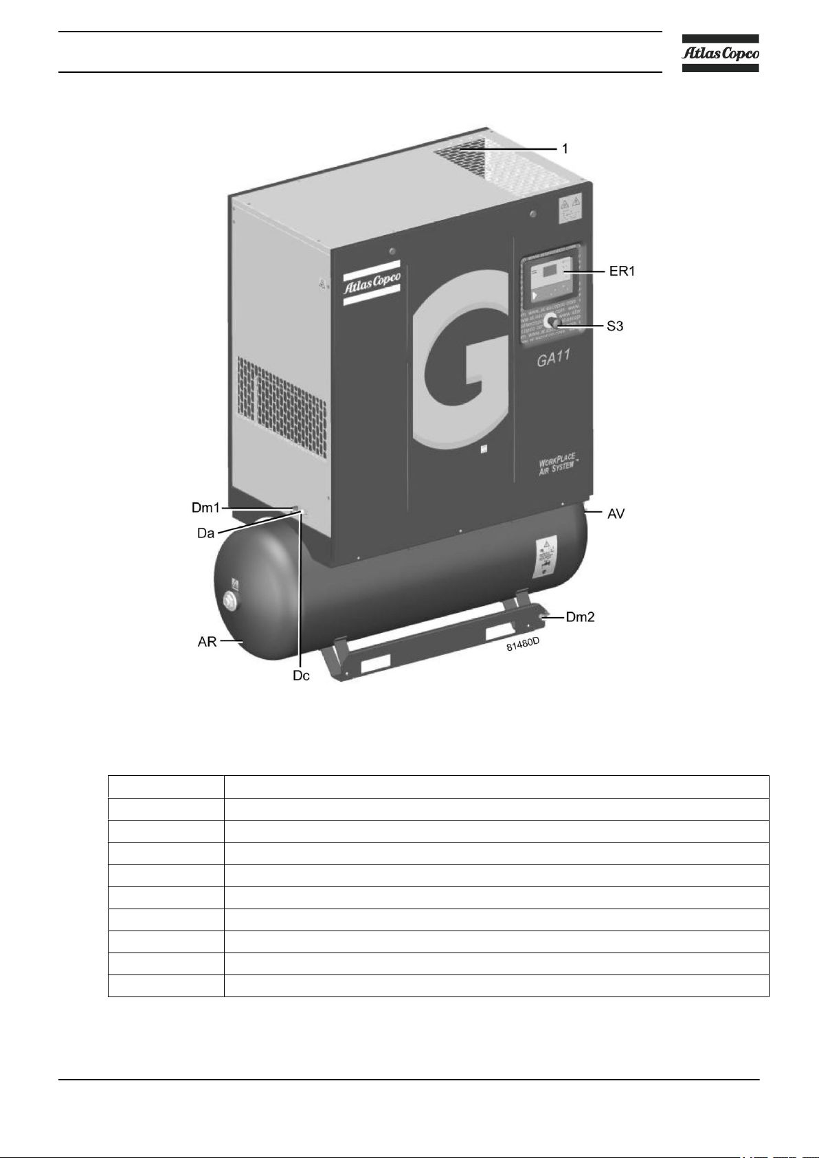
Front view, Workplace tank-mounted with Elektronikon® controller
Ref. Name
AR Air receiver
AV Air outlet valve
Da Automatic condensate outlet
Dc OSD drain outlet (option)
Dm1 Manual condensate drain valve
Dm2 Manual condensate drain valve
ER1 Elektronikon® controller
S3 Emergency stop button
1 Electric cable entry
2920 7090 51 13
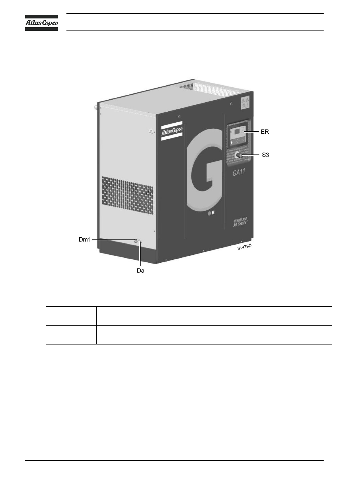
Floor-mounted version
The compressors are installed directly on the floor.
Instruction book
GA 11 Pack, Floor mounted, Front view
ER Elektronikon® controller
S3 Emergency stop button
Dm1 Manual condensate drain valve
Da Automatic condensate outlet
14 2920 7090 51

Instruction book
Floor-mounted Workplace Pack compressor, rear view
Ref. Name
AF Air filter
AV Air outlet valve
C Combicooler
FN Fan motor
M1 Drive motor
2920 7090 51 15
2.2 Air flow
Flow diagrams
Instruction book
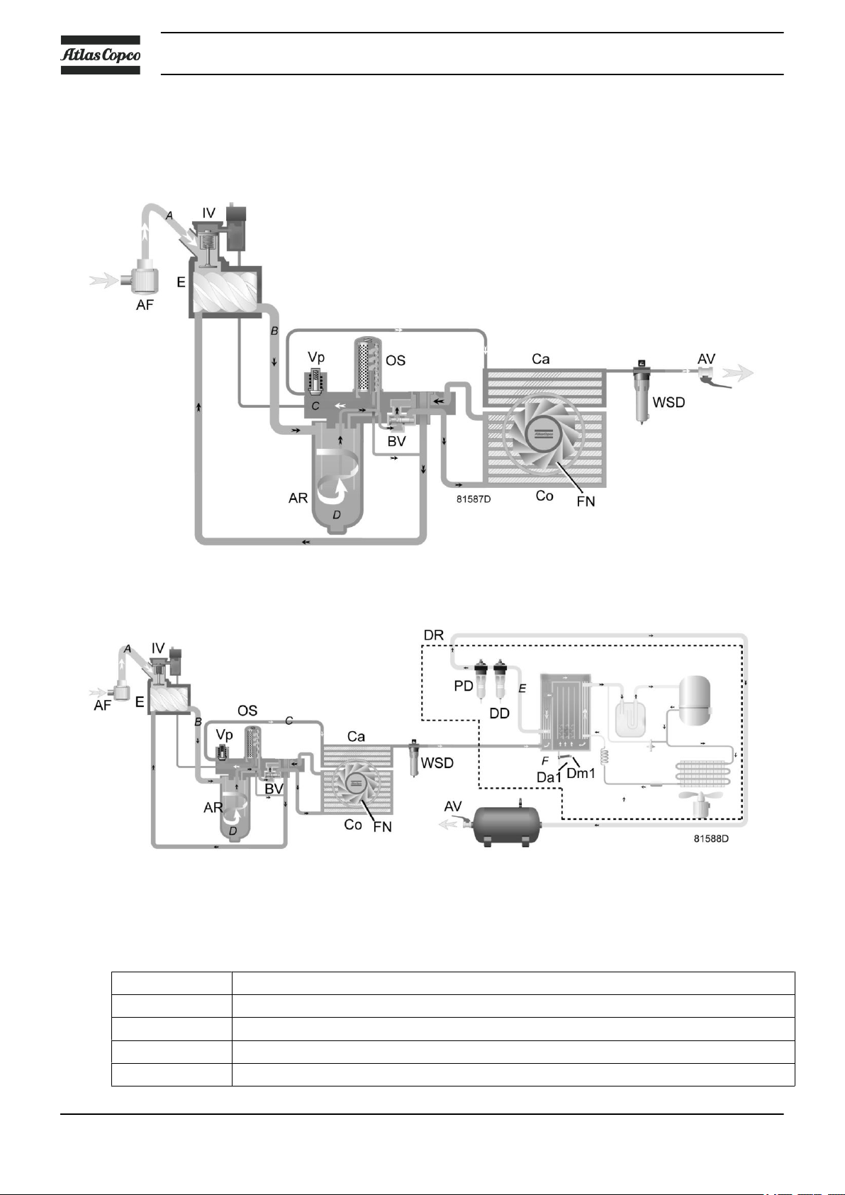
References
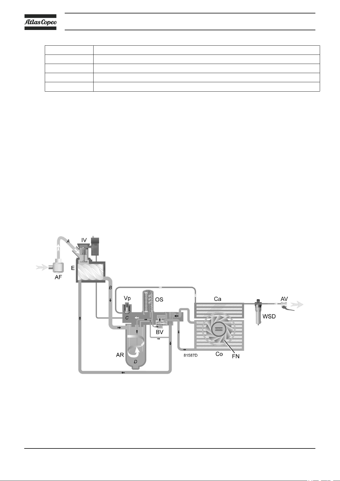
Ref. Description
A Intake air
B Air/oil mixture
C Hot compressed air
D Oil
For Workplace units
For Workplace Full-Feature units
16 2920 7090 51
Instruction book
Ref. Description
E Dry air
F Condensate
G Dry air (compressors with integrated dryer)
Description
Air drawn through filter (AF) and open inlet valve (IV) into compressor element (E) is compressed.
Compressed air and oil flow into the air receiver/oil separator (OT). The air flows through minimum pressure
valve (Vp) to air cooler (Ca).
Minimum pressure valve (Vp) prevents the receiver pressure from dropping below a minimum pressure and
includes a check valve which prevents blow-back of compressed air from the net.
On Full-Feature compressors the air flows through air dryer (DR).
Air is discharged through outlet valve (AV).
2.3 Oil system
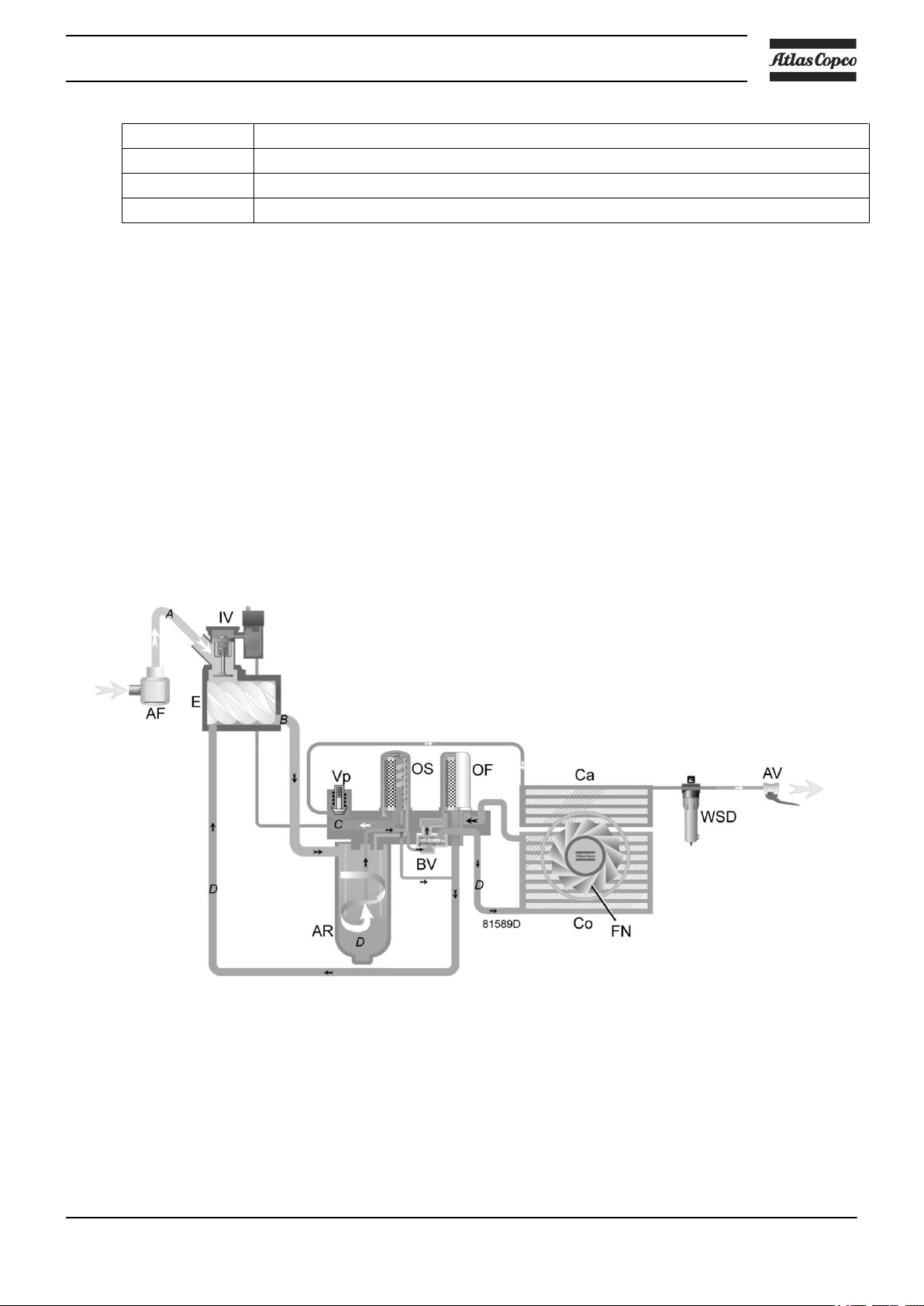
Flow diagram
Oil system
2920 7090 51 17
References Description
A Intake air
B Air/oil mixture
C Compressed air
D Oil
Description
The air/oil mixture coming from the compressor element flows into the oil separator/tank, where most of the
oil is separated by centrifugal action. The oil collects in the lower part of air receiver/oil separator (OT) which
serves as oil tank. The remaining oil is removed by oil separator (OS). A small pipe returns the separated oil
towards the compressor element.
Air pressure forces the oil from oil separator/tank (OT) through oil cooler (Co) and filter (OF) towards
compressor element (E).
The system comprises a thermostatic bypass valve (BV). Only when the oil is warm, the valve allows the oil
to pass through the oil cooler.
Instruction book
2.4 Cooling system
Flow diagram
Cooling system
18 2920 7090 51
Instruction book
References Description
A Intake air
B Compressed air/oil
C Compressed air
D Oil
Description
The cooling system comprises of air cooler (Ca) and oil cooler (Co). The cooling air is generated by a fan
(FN). The fan is set on the shaft of the motor.
2.5 Condensate system
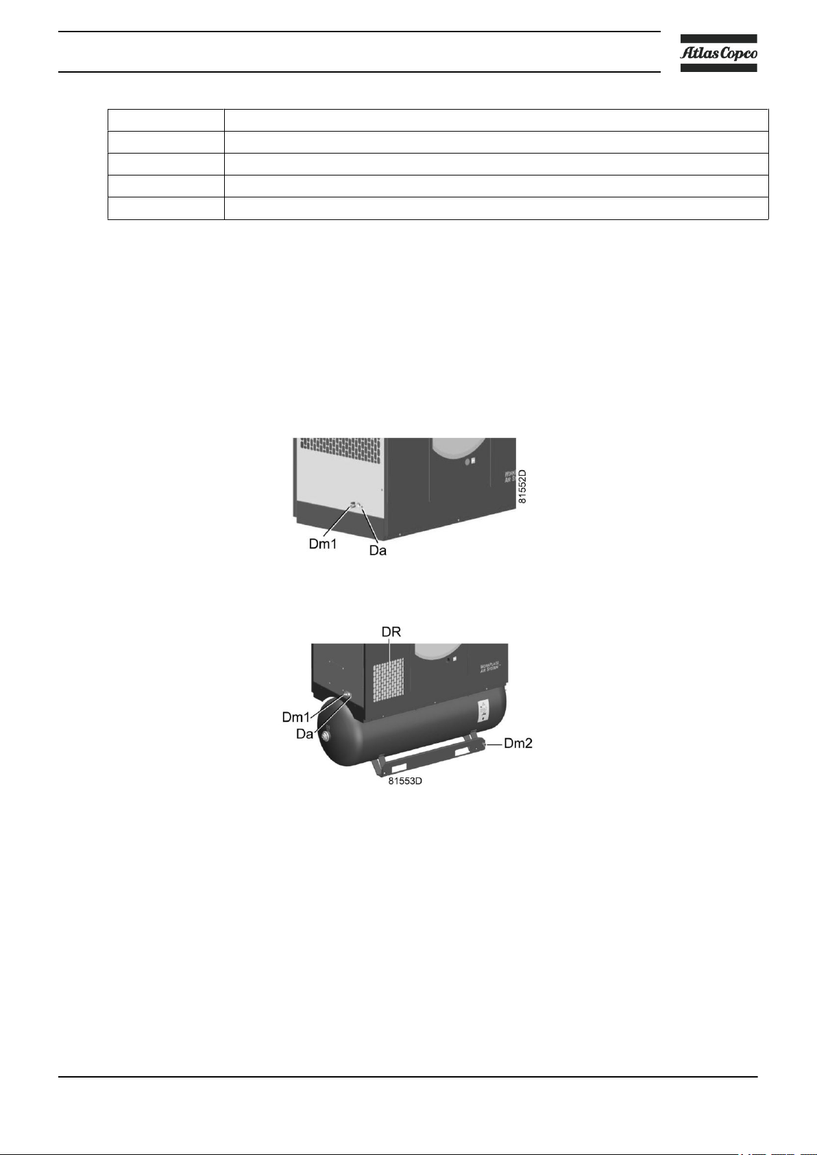
Condensate drains
Condensate drains on a floor-mounted version
Condensate drains on a tank-mounted Full-Feature version
Pack versions are equipped with a condensate trap in the air outlet system. The trap is equipped with a valve
for automatic draining during operation and is connected to the automatic drain outlet (Da) and to a manually
operated valve (Dm1) for draining after stopping the compressor.
Tank-mounted compressors are also provided with a manual condensate drain valve (Dm2) for draining the
condensate trapped in the receiver.
Full-Feature versions are equipped with an electronic water drain for automatic draining of the condensate
during operation. The electronic drain is connected to automatic drain outlet (Da) and to a manually operated
valve (Dm1) for draining after stopping the compressor.
2920 7090 51 19
2.6 Regulating system
Flow diagram
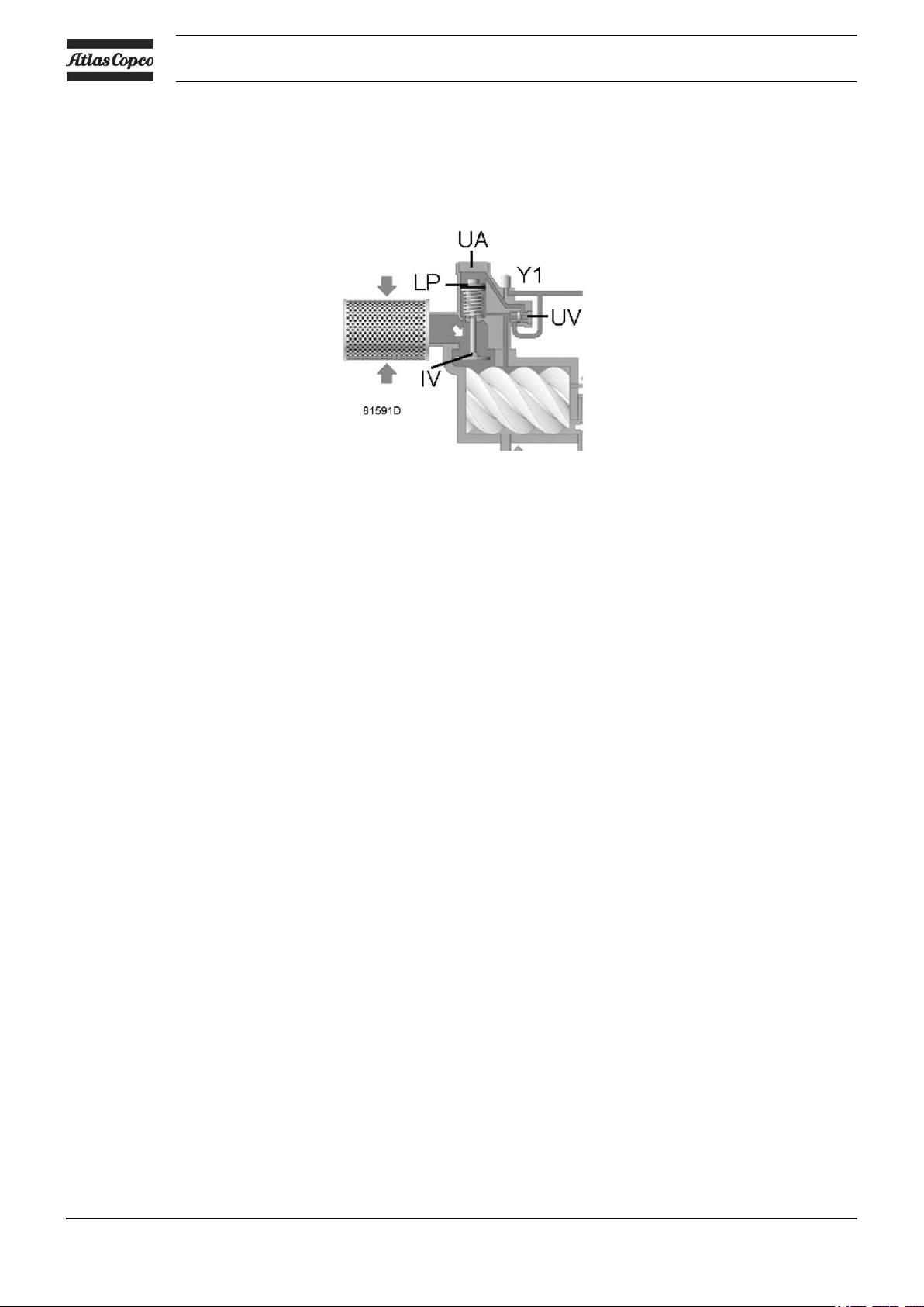
Unloading
Instruction book
Loading
If the air consumption is less than the air output of the compressor, the net pressure increases. When the net
pressure reaches the unloading pressure, solenoid valve (Y1) is de-energised.
• The control pressure present in the chambers of loading plunger (LP) and unloading valve (UV) is vented
to atmosphere via solenoid valve (Y1).
• Loading plunger (LP) moves upwards and causes inlet valve (IV) to close the air inlet opening.
• Unloading valve (UV) is opened by the pressure in the oil separator vessel. The pressure from the oil
separator vessel is released into atmosphere through the unloader (UA).
• The pressure in the oil separator vessel stabilises at low value. A reduced amount of air is compressed to
guarantee a minimal pressure, required for lubrication during unloaded operation.
Air output is stopped (0%), the compressor runs unloaded.
When the net pressure decreases to the loading pressure, solenoid valve (Y1) is energised.
• Control pressure is fed from the oil separator vessel via solenoid valve (Y1) to loading plunger (LP) and
unloading valve (UV).
• Unloading valve (UV) closes the air blow-off opening. Loading plunger (LP) moves downwards and
causes inlet valve (IV) to open fully.
Air delivery is resumed (100%), the compressor runs loaded.
2.7 Electrical system
General
Also consult sections Electrical diagrams and Electrical connections.
The electrical system comprises following components:
20 2920 7090 51
Instruction book
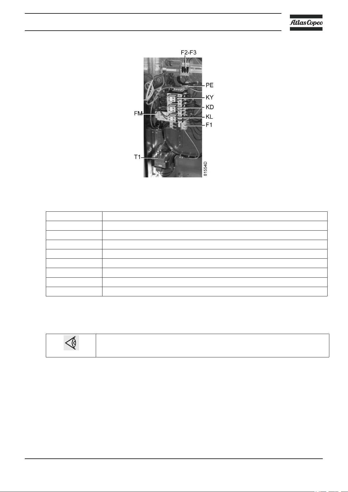
Reference Description
F1 Fuses
F2-F3 Fuses
FM Overload relay, compressor motor
KD Delta contactor
KY Star contactor
KL Line contactor
T1 Transformer
PE Earth terminal
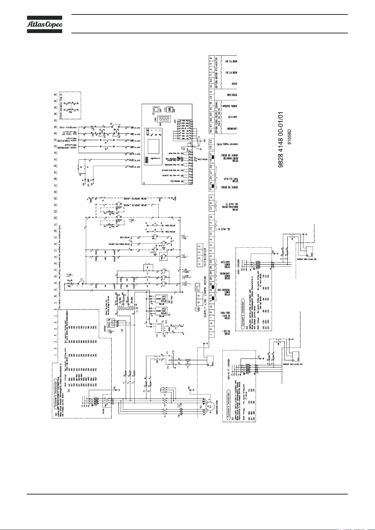
2.8 Electrical diagrams
The service diagram and the explanatory designations below are given as typical example
only. Some of the texts may not be applicable to a specific case.
The applicable service diagram is situated in the electric cubicle of the compressor.
Electric cabinet
2920 7090 51 21
Instruction book
Service diagram
Designations
22 2920 7090 51
Instruction book
Reference Sensors / solenoid valves / electronic water drain
PT20 Pressure sensor, air outlet
TT11 Temperature sensor, element outlet
TT90 Temperature sensor, dew-point (Full Feature)
TT91 Temperature sensor, ambient (Full Feature)
Y1 Loading solenoid valve
Reference Motors
M1 Compressor motor
M2 Fan motor, cooler
Reference Electric cabinet
E1 Compressor control module
F1-F11 Fuses
FM1 Overload relay, compressor motor
KMD Contactor for dryer (Full-Feature)
KL Line contactor
KY Star contactor
KD Delta contactor
T1 Transformer
KA Auxiliary relay for heaters and auxiliary fan
S1' Remote Start/programmed stop
S2' Remote Load/unload
S3 Emergency stop
S3' Remote emergency stop
Reference Control module
I Start button
0 Stop button
K01 Blocking relay
K02 Auxiliary relay, star contactor
K03 Auxiliary relay, delta contactor
K04 Auxiliary relay, loading/unloading
K05 Auxiliary relay, general shutdown
K06 Auxiliary relay, dryer
Reference Optional equipment
A1 Dryer (Full-Feature)
B1/B2 Electronic Water Drain (EWD)
KPH Phase sequence relay
K34/K35 Thermistor relay
2920 7090 51 23
Reference Optional equipment
R1/K34 Drive motor thermistor protection, shut-down
R96 Anti-condensation heaters
KE Auxiliary relay, load/unload signal for ES100
S10 Main power isolating switch
Y2 Solenoid valve for modulating control
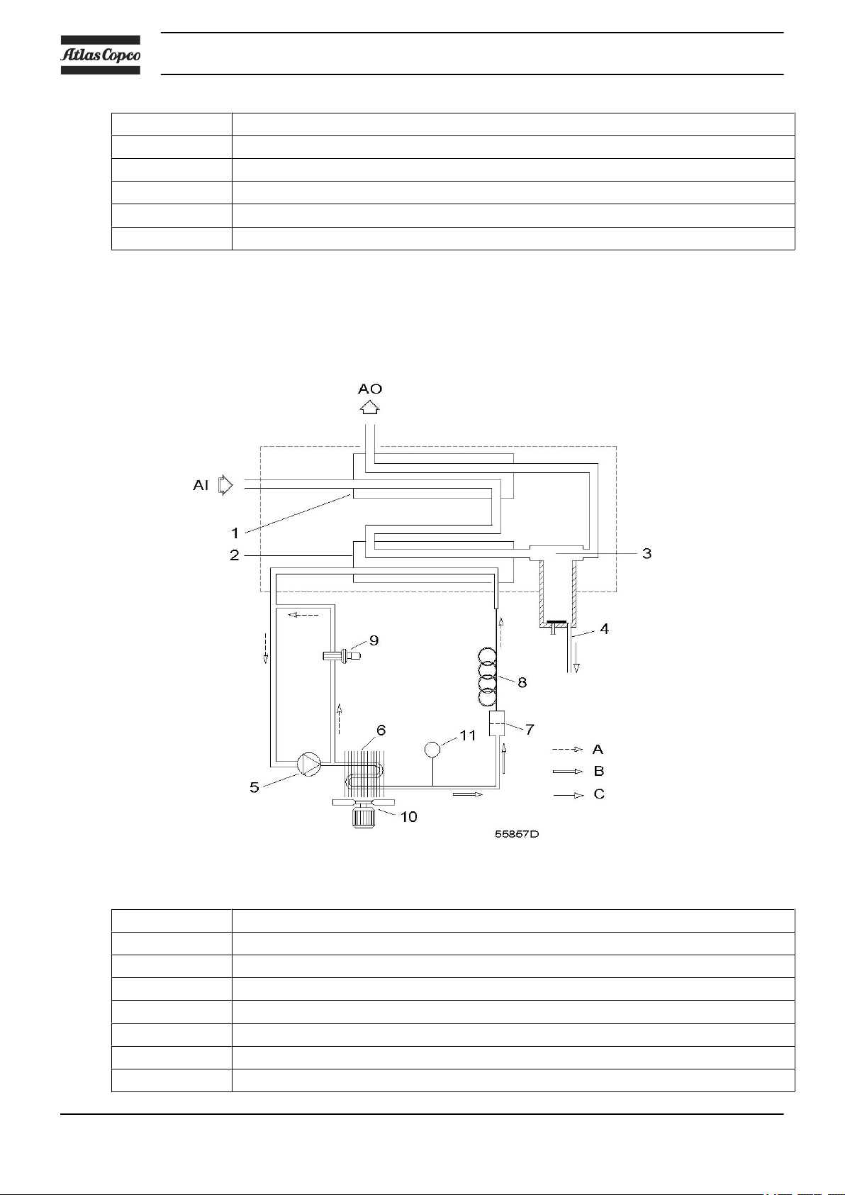
2.9 Air dryer
Flow diagram
Instruction book
Air dryer
Reference Name
AI Air inlet
AO Air outlet
1 Air/air heat exchanger
2 Air/refrigerant heat exchanger/evaporator
3 Condensate separator
4 Automatic drain / condensate outlet
5 Refrigerant compressor
24 2920 7090 51
Instruction book
Reference Name
6 Refrigerant condenser
7 Liquid refrigerant dryer/filter
8 Capillary
9 Hot gas by-pass valve
10 Condenser cooling fan
11 Pressure switch, fan control
Compressed air circuit
Compressed air enters heat exchanger (1) and is cooled by the outgoing, cold, dried air. Water in the incoming
air starts to condense. The air then flows through heat exchanger/evaporator (2), where the refrigerant
evaporates, causing the air to be cooled further to close to the evaporating temperature of the refrigerant. More
water in the air condenses. The cold air then flows through separator (3) where all the condensate is separated
from the air. The condensate is automatically drained through outlet (4).
The cold, dried air flows through heat exchanger (1) where it is warmed up by the incoming air.
Refrigerant circuit
Compressor (5) delivers hot, high-pressure refrigerant gas which flows through condenser (6) where most of
the refrigerant condenses.
The refrigerant enters evaporator (2) where it withdraws heat from the compressed air by further evaporation
at constant pressure. The heated refrigerant leaves the evaporator and is sucked in by the compressor (5).
By-pass valve (9) regulates the refrigerant flow. Fan (10) is switched on or off by switch (11) depending on
the loading degree of the refrigerant circuit.
The refrigerant compressor motor has a built-in thermic protection. If the motor stops after tripping
of the thermic protection, it may take up to 2 hours for the motor windings to cool down and before
the motor can restart.
2920 7090 51 25
3 Elektronikon® controller
Instruction book
3.1
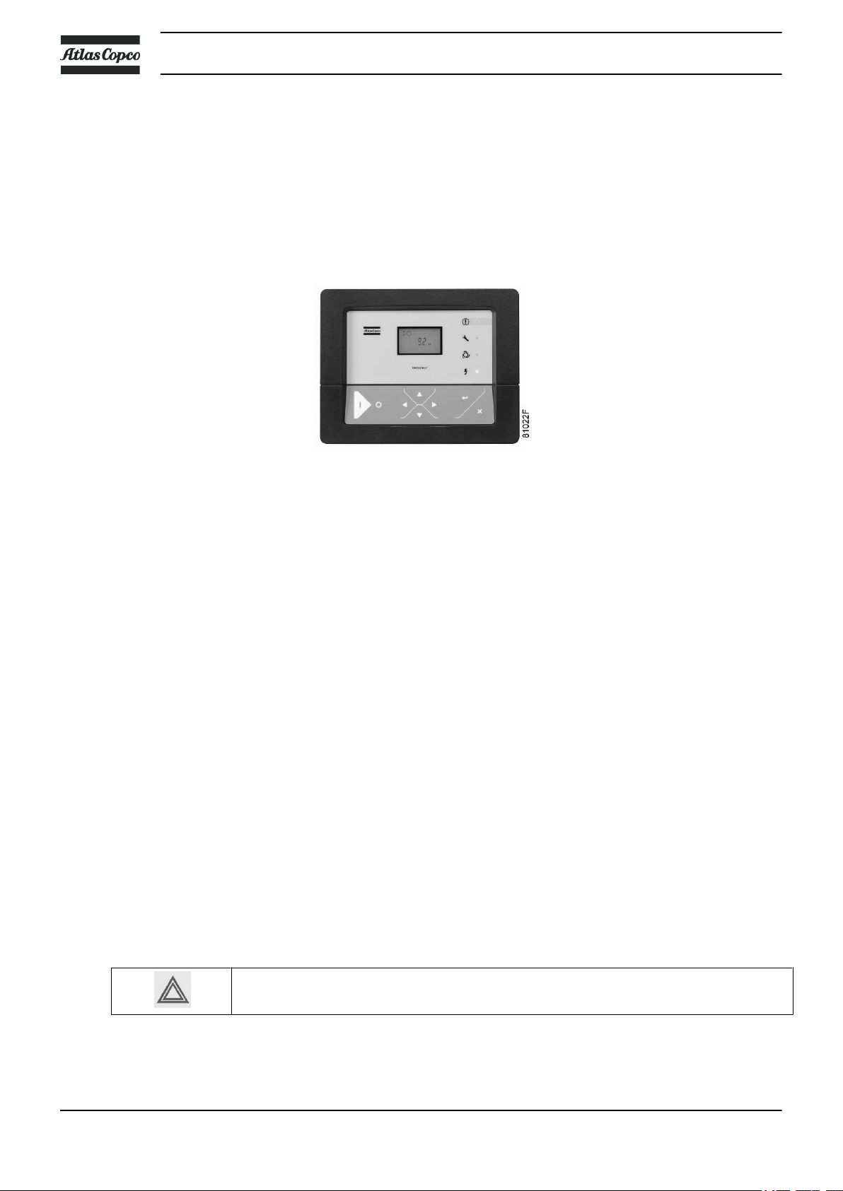
Control panel
Introduction
Elektronikon® regulator
In general, the Elektronikon® regulator has following functions:
• Controlling the compressor
• Protecting the compressor
• Monitoring components subject to service
• Automatic restart after voltage failure (made inactive)
Automatic control of the compressor
The regulator maintains the net pressure between programmable limits by automatically loading and unloading
the compressor. A number of programmable settings, e.g. the unloading and loading pressures, the minimum
stop time and the maximum number of motor starts are taken into account.
The regulator stops the compressor whenever possible to reduce the power consumption and restarts it
automatically when the net pressure decreases. If the expected unloading period is to short, the compressor
is kept running to prevent too short stand-still periods.
Protecting the compressor
Shut-down
If the compressor element outlet temperature exceeds the programmed shut-down level, the compressor will
be stopped. This will be indicated on the display of the regulator. The compressor will also be stopped in case
of overload of the drive motor.
Air-cooled compressors will also be stopped in the event of overload of the fan motor.
Before remedying, consult the Safety precautions.
Shut-down warning
A shut-down warning level is a programmable level below the shut-down level.
26 2920 7090 51
Instruction book
If one of the measurements exceeds the programmed shut-down warning level, this will also be indicated to
warn the operator before the shut-down level is reached.
Service warning
If the service timer exceeds a programmed value, this will be indicated on the display to warn the operator to
carry out some service actions.
Automatic restart after voltage failure
The regulator has a built-in function to automatically restart the compressor when the voltage is restored after
voltage failure. This function is deactivated in compressors leaving the factory. If desired, the function can
be activated. Consult the Atlas Copco Customer Centre.
If activated, and if the regulator was in the automatic operation mode, the compressor will
automatically restart when the supply voltage to the module is restored!
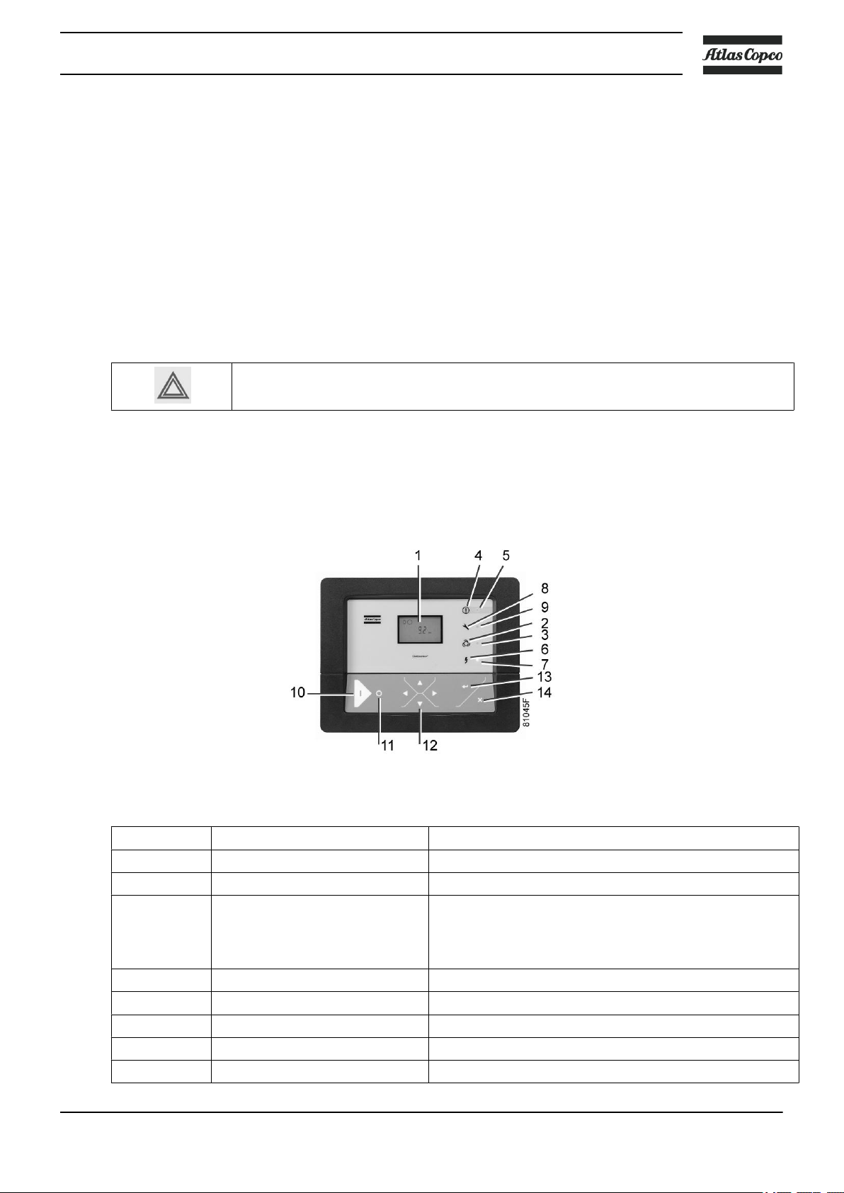
3.2 Control panel
Detailed description
Reference Designation Function
1 Display Shows icons and operating conditions.
2 Automatic operation symbol
3 LED, Automatic operation Indicates that the regulator is automatically controlling the
4 Warning symbol
5 LED, Warning Is lit if a warning condition exists.
6 Voltage symbol
7 LED, Voltage on Indicates that the voltage is switched on.
8 Service symbol
Control panel of the Elektronikon with standard display
compressor: the compressor is loaded, unloaded, stopped
and restarted depending on the air consumption and the
limitations programmed in the regulator.
2920 7090 51 27
Reference Designation Function
9 LED, Service Is lit when service is needed.
10 Start button This button starts the compressor. Automatic operation
11 Stop button This button is used to stop the compressor. Automatic
12 Scroll buttons Use these buttons to scroll trough the menu .
13 Enter button Use this button to confirm the last action
14 Escape button Use this button to go to previous screen or to end the
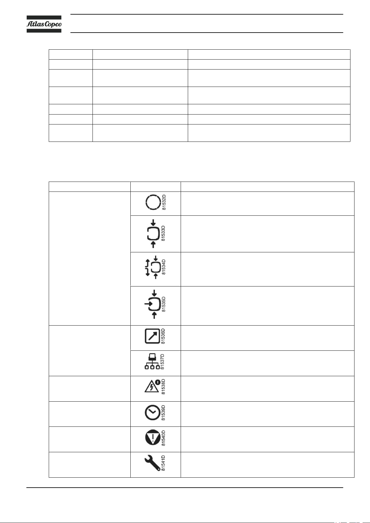
3.3 Icons used on the display
Function Icon Description
Compressor status When the compressor is stopped, the icon stands still.
Instruction book
LED (3) lights up. The Elektronikon is operative.
operation LED (3) goes out.
current action.
When the compressor is running, the icon is rotating.
Motor stopped
Running unloaded
Running loaded
Machine control mode Remote start / stop
LAN control
Automatic restart after
voltage failure
Automatic restart after voltage failure is active
Timer
Active protection functions Emergency stop
Service Service required
28 2920 7090 51
 Loading...