

Atlas Copco GA55, GA5, GA90C User Manual

6060560 │COMPRESSOR 460/60/3 116CFM │Cu
┌─Item Text ──────────────────────────────────────────────────────────────────┐
│ COMPRESSOR 460/60/3 116 CFM 150 PSI │
│ │
│ Manufacturer: ATLAS COPCO │
│ Mfr Part No : GA22FF │
│ Size : 116 CFM @ 150 PSI │
│ Add'l Info : ROTARY SCREW, SINGLE STAGE, OIL INJECTED, │
│ AIR COOLED, FULL FEATURE UNIT │
│ WITH INTEGRATED REFRIGERATED DRYER, │
│ COMPRESSOR FAILURE DRY CONTACTS. │
│ 30 HP, │
│ 460V, 3 PHASE, 60 HZ │
│ 40 IN LONG X 31 IN WIDE X 71 IN HIGH 1318 LBS. │
│ EACH COMPRESSOR INCLUDES: FOOD GRADE LUBRICANT (GA-FG) │
│ AND GENERAL ALARM CONTACTS │
└──────────────────────────────────────────────────────────────────────────────────┘


Atlas Copco Stationary Air Compressors
Important
1. This Manual applies exclusively to the compressors equipped with the Atlas Copco Elektronikon
regulator.
2. This Manual must be used together with the relevant Instruction books for the compressors.
*2920120705*
No. 2920 1207 05
Registration code:APC G5-10/'98 / 38 / 995
APC G11-22 / 38 / 983
APC G30-45/'98 / 38 / 995
APC G55-90C/'96 / 38 / 988
Replaces 2920 1207 04
1999-04
GA5 up to GA90C
Web-site: http://www.atlascopco-compressors.com
•
Copyright 1999, Atlas Copco Airpower n.v., Antwerp, Belgium.
Any unauthorized use or copying of the contents or any part thereof is prohibited. This applies
in particular to trademarks, model denominations, part numbers and drawings.
• This instruction book meets the requirements for instructions specified by the machinery directive
89/392/EEC and is valid for CE as well as non-CE labelled machines.
User Manual for Elektronikon
regulator

2920 1207 05
2
User manual
Contents
Page
10.3 Calling up running hours and service level . . . . . 14
10.4 Service reset . . . . . . . . . . . . . . . . . . . . . . . . . . . . . 14
11 Test submenu: display test . . . . . . . . . . . . . . . . . . . . . 14
11.1 Function . . . . . . . . . . . . . . . . . . . . . . . . . . . . . . . . 14
11.2 Procedure . . . . . . . . . . . . . . . . . . . . . . . . . . . . . . . 14
12 Modify settings submenu: modifying settings for
regulation, protection and service. . . . . . . . . . . . . . . 15
12.1 Function . . . . . . . . . . . . . . . . . . . . . . . . . . . . . . . . 15
12.2 Procedure . . . . . . . . . . . . . . . . . . . . . . . . . . . . . . . 15
12.3 Modifying compressor regulation settings . . . . . . 15
12.3.1 Modifying the loading pressure. . . . . . . . . 15
12.4 Modifying protection settings. . . . . . . . . . . . . . . . 16
12.4.1 Element outlet temperature . . . . . . . . . . . . 16
12.4.2 Dewpoint temperature . . . . . . . . . . . . . . . . 17
12.4.3 Cooling water outlet temperature . . . . . . . 17
12.5 Modifying service settings . . . . . . . . . . . . . . . . . . 18
13 Timer submenu: programming compressor start/stop
commands . . . . . . . . . . . . . . . . . . . . . . . . . . . . . . . . . . 19
13.1 Function . . . . . . . . . . . . . . . . . . . . . . . . . . . . . . . . 19
13.2 Procedure . . . . . . . . . . . . . . . . . . . . . . . . . . . . . . . 19
13.2.1 To program start/stop commands . . . . . . . 19
13.2.2 To activate/deactivate the timer . . . . . . . . 19
13.2.3 To display the list of commands . . . . . . . . 19
13.2.4 To modify a command. . . . . . . . . . . . . . . . 19
13.2.5 To add a command . . . . . . . . . . . . . . . . . . 20
13.2.6 To delete a command. . . . . . . . . . . . . . . . . 20
14 Configuration submenu: reprogramming time,
date, display language, units, motor start mode
and date format. . . . . . . . . . . . . . . . . . . . . . . . . . . . . . 21
14.1 Function . . . . . . . . . . . . . . . . . . . . . . . . . . . . . . . . 21
14.2 Procedure . . . . . . . . . . . . . . . . . . . . . . . . . . . . . . . 21
15 Saved data submenu: calling up compressor
data saved by regulator . . . . . . . . . . . . . . . . . . . . . . . 21
15.1 Function . . . . . . . . . . . . . . . . . . . . . . . . . . . . . . . . 21
15.2 Procedure . . . . . . . . . . . . . . . . . . . . . . . . . . . . . . . 21
15.2.1 Example of the last shut-down data . . . . . 21
16 More function: quick look at actual compressor
status . . . . . . . . . . . . . . . . . . . . . . . . . . . . . . . . . . . . . 22
16.1 Function . . . . . . . . . . . . . . . . . . . . . . . . . . . . . . . . 22
16.2 Procedure . . . . . . . . . . . . . . . . . . . . . . . . . . . . . . . 22
17 Manually loading/unloading . . . . . . . . . . . . . . . . . . . 23
17.1 Function . . . . . . . . . . . . . . . . . . . . . . . . . . . . . . . . 23
17.2 Manually unloading . . . . . . . . . . . . . . . . . . . . . . . 23
17.3 Manually loading . . . . . . . . . . . . . . . . . . . . . . . . . 23
18 Programmable settings. . . . . . . . . . . . . . . . . . . . . . . . 23
18.1 Regulation settings . . . . . . . . . . . . . . . . . . . . . . . . 23
18.2 Protection settings. . . . . . . . . . . . . . . . . . . . . . . . . 24
18.3 Service settings . . . . . . . . . . . . . . . . . . . . . . . . . . . 25
Page
1 General description . . . . . . . . . . . . . . . . . . . . . . . . . . . 3
1.1 Controlling the compressor . . . . . . . . . . . . . . . . . . 3
1.2 Protecting the compressor . . . . . . . . . . . . . . . . . . . 3
1.2.1 Shut-down and motor overload . . . . . . . . . . 3
1.2.2 Shut-down warning . . . . . . . . . . . . . . . . . . . 3
1.2.3 Control of motor rotation direction. . . . . . . 3
1.2.4 Warning . . . . . . . . . . . . . . . . . . . . . . . . . . . . 3
1.3 Monitoring components subject to service (service
warning) . . . . . . . . . . . . . . . . . . . . . . . . . . . . . . . . . 3
1.4 Automatic restart after voltage failure . . . . . . . . . . 3
2 Control panel. . . . . . . . . . . . . . . . . . . . . . . . . . . . . . . . . 4
2.1 Indicators, keys and buttons . . . . . . . . . . . . . . . . . . 4
2.2 Pictographs . . . . . . . . . . . . . . . . . . . . . . . . . . . . . . . 4
3 Display - keys . . . . . . . . . . . . . . . . . . . . . . . . . . . . . . . . 5
3.1 Display . . . . . . . . . . . . . . . . . . . . . . . . . . . . . . . . . . 5
3.2 Scroll keys. . . . . . . . . . . . . . . . . . . . . . . . . . . . . . . . 5
3.3 Tabulator key . . . . . . . . . . . . . . . . . . . . . . . . . . . . . 5
3.4 Function keys . . . . . . . . . . . . . . . . . . . . . . . . . . . . . 5
4 Menu-driven control programs. . . . . . . . . . . . . . . . . . 5
4.1 Function of control programs . . . . . . . . . . . . . . . . . 5
4.2 Selecting a menu. . . . . . . . . . . . . . . . . . . . . . . . . . . 9
4.2.1 Main display . . . . . . . . . . . . . . . . . . . . . . . . 9
4.2.2 Calling up other menus . . . . . . . . . . . . . . . . 9
4.2.3 Returning to the main menu or main display9
5 Main display: compressor status in short/gateway
to all functions. . . . . . . . . . . . . . . . . . . . . . . . . . . . . . . . 9
5.1 Function . . . . . . . . . . . . . . . . . . . . . . . . . . . . . . . . . 9
5.2 Procedure . . . . . . . . . . . . . . . . . . . . . . . . . . . . . . . . 9
6 Main menu: gateway to other functions . . . . . . . . . 10
6.1 Function . . . . . . . . . . . . . . . . . . . . . . . . . . . . . . . . 10
6.2 Procedure . . . . . . . . . . . . . . . . . . . . . . . . . . . . . . . 10
7 Status data submenu: calling up status of protection
functions and resetting . . . . . . . . . . . . . . . . . . . . . . . . 10
7.1 Function . . . . . . . . . . . . . . . . . . . . . . . . . . . . . . . . 10
7.2 Procedure . . . . . . . . . . . . . . . . . . . . . . . . . . . . . . . 10
7.2.1 No shut-down warning message or
shut-down message exists . . . . . . . . . . . . . 11
7.2.2 A shut-down message exists . . . . . . . . . . . 11
7.2.3 A shut-down warning message exists . . . . 11
7.2.4 A warning message exists . . . . . . . . . . . . . 11
7.3 Shut-down reset . . . . . . . . . . . . . . . . . . . . . . . . . . 12
7.4 Reset of motor overload . . . . . . . . . . . . . . . . . . . . 12
8 Measured data submenu: calling up measured data 12
8.1 Function . . . . . . . . . . . . . . . . . . . . . . . . . . . . . . . . 12
8.2 Procedure . . . . . . . . . . . . . . . . . . . . . . . . . . . . . . . 12
9 Hours submenu: calling up running hours, loading
hours, regulator hours and motor starts . . . . . . . . . 13
9.1 Function . . . . . . . . . . . . . . . . . . . . . . . . . . . . . . . . 13
9.2 Procedure . . . . . . . . . . . . . . . . . . . . . . . . . . . . . . . 13
10 Service submenu: calling up and resetting service
messages. . . . . . . . . . . . . . . . . . . . . . . . . . . . . . . . . . . . 14
10.1 Function . . . . . . . . . . . . . . . . . . . . . . . . . . . . . . . . 14
10.2 Calling up service messages . . . . . . . . . . . . . . . . . 14

2920 1207 05
3
User manual
1 GENERAL DESCRIPTION
The electronic regulator automatically controls the compressor,
i.e.:
- Loading and unloading the compressor
- Stopping the compressor whenever possible
- Restarting the compressor when required
In order to control the compressor and to read and modify
programmable parameters, the regulator has a control panel
provided with:
- LEDs indicating the status of the compressor
- A display indicating the operating conditions, a service need
or a fault
- Keys to control the compressor and to have access to the
data collected by the regulator
- Buttons to manually start and stop the compressor
- An emergency stop button
In general, the regulator has following functions:
- Controlling the compressor
- Protecting the compressor
- Monitoring components subject to service
- Automatic restart after voltage failure (made inactive)
1.1 Controlling the compressor
The regulator maintains the net pressure between programmable
limits by automatically loading and unloading the compressor
depending on the air consumption.
The regulator takes into account a number of programmable
settings, such as:
- Unloading pressure
- Loading pressure
- Minimum stop time
- Maximum number of motor starts
The regulator stops the compressor whenever possible (when
the expected unloading period exceeds a programmed value) to
reduce the power consumption and restarts it automatically when
the net pressure decreases. In case the expected unloading period
is below a programmed value, the regulator keeps the compressor
running to prevent too-short standstill periods.
When the compressor has stopped automatically and the net
pressure decreases, the regulator will start the compressor before
the net pressure has dropped to the loading pressure to prevent
the net pressure from falling under the programmed minimum
level.
When stopping the compressor manually, the regulator will
unload the compressor for 30 seconds and then stop the
compressor. 1)
1.2 Protecting the compressor
1.2.1 Shut-down and motor overload
If the compressor element outlet temperature exceeds the
programmed shut-down level, the compressor will be stopped.
This will be indicated on the control display.
The compressor will also be stopped in case of overload of the
drive motor or fan motor. 2)
1.2.2 Shut-down warning
If the compressor element outlet temperature exceeds a
programmed value just below the shut-down level, this will also
be indicated to warn the operator before the shut-down level is
reached.
1.2.3 Control of motor rotation direction
Regulators for GA90C and for later production GA30 up to -75
are provided with a control function for correct rotation direction
of the motor: a message will appear on the display of the regulator
if the rotation direction is wrong. In this case, switch off the
voltage and reverse two incoming lines.
1.2.4 Warning
A warning message also appears if the cooling water temperature
or dewpoint temperature exceeds the warning level. See section
7.2.4.
1.3 Monitoring components subject to
service (service warning)
The regulator continuously monitors critical components (oil,
oil filter, oil separator and air filter). Each input is compared to
programmed limits. Exceeding these limits causes a message
on the control display to warn the operator to replace the
indicated component.
1.4 Automatic restart after voltage failure
The regulator has a built-in function to automatically restart the
compressor if the voltage is restored after voltage failure. For
compressors leaving the factory, this function is made inactive.
If desired, the function can be activated. Consult Atlas Copco.
Footnotes chapter 1
1) If the compressor was running at that moment in automatic
unloading condition for 10 seconds, it will remain running
unloaded for 30 - 10 = 20 seconds before stopping.
2) For GA30 up to GA90C only.

2920 1207 05
4
User manual
Fig. 2.1. Control panel
2 CONTROL PANEL
2.1 Indicators, keys and buttons (Fig. 2.1)
Ref. Designation Function
1 Automatic Indicates that the regulator is
operation LED automatically controlling the
compressor: the compressor is
loaded, unloaded, stopped and
restarted depending on the air
consumption and the limitations
programmed in the regulator.
2 Voltage on LED Indicates that the voltage is
switched on.
3 General alarm LED Is alight if a warning or shut-down
warning condition exists or if a
sensor is out of order. See section
7.
Blinks in case of shut-down, if a
sensor with shut-down function
(e.g. TT11) is out of order or after
an emergency stop. See section 7.
4 Display Indicates messages concerning the
compressor operating condition, a
service need or a fault. See section
3.1.
5 Function keys Keys to control and program the
compressor. See section 3.4.
6 Scroll keys Keys to scroll through the display .
See section 3.2.
7 Tabulator key Key to go to the next field of the
display. See section 3.3.
8 Start button Push button to start the
compressor. LED (1) lights up
indicating that the regulator is
operative (in automatic operation).
The LED goes out after unloading
the compressor manually .
9 Stop button Push button to stop the
compressor. LED (1) goes out.
The compressor will stop after
running in unloaded condition for
30 seconds. See also section 1.1.
S3 Emergency Maintained-action push button to
stop button stop the compressor immediately
in case of emergency. After
remedying the trouble, unlock the
button by turning it to the left or
by pulling it out.
2.2 Pictographs (Fig. 2.1)
Ref. Designation
10 Emergency stop
11 Automatic operation
12 Voltage on
13 Alarm
Delivery air
bar 7.0
Auto loaded
Menu More Unld
F1 F2 F3
Fig. 2.2. Typical example of a display
411 122
1
3
5
S3
10
6
7
9
8
50503F
13

2920 1207 05
5
User manual
3 DISPLAY - KEYS
3.1 Display (4-Fig. 2.1)
The display has four lines of 16 characters. A typical display is
shown in Fig. 2.2. It indicates:
1. On the first three lines:
- The name of the sensor of which the actual reading is
displayed
- The unit and actual reading of the sensor
- Messages regarding the compressor operating condition
(compressor loaded, off, etc.), a service need (e.g. for
the oil filter and air filter) or a fault (e.g. shut-down)
2. On the fourth line, just above the three function keys (F1/
F2/F3), the actual functions of these keys.
3.2 Scroll keys (6-Fig. 2.1)
These keys, labelled with vertical arrows, allow to scroll through
the display.
As long as a downwards pointing arrow is shown at the utmost
right position of the display, the key (6) with the same symbol
can be used to see the next item.
As long as an upwards pointing arrow is shown at the utmost
right position of the display, the key (6) with the same symbol
can be used to see the previous item.
3.3 Tabulator key (7-Fig. 2.1)
This key, labelled with two horizontal arrows, allows the operator
to go to the next field of the display, e.g. during modifying of
programmable parameters.
3.4 Function keys (5-Fig. 2.1)
The keys are used:
- To manually load/unload the compressor
- To call up or program settings
- To reset an active motor overload, shut-down or service
message, or an emergency stop
- To have access to all data collected by the regulator
The function keys allow to make the required selection from a
menu of possibilities. The functions of the keys vary depending
on the displayed menu. The actual function is abbreviated and
indicated on the bottom line of the display just above the relevant
key. Only the active and relevant functions at a moment are
shown.
4 MENU-DRIVEN CONTROL
PROGRAMS
In order to facilitate programming and controlling, menu-driven
control programs have been implemented in the regulator.
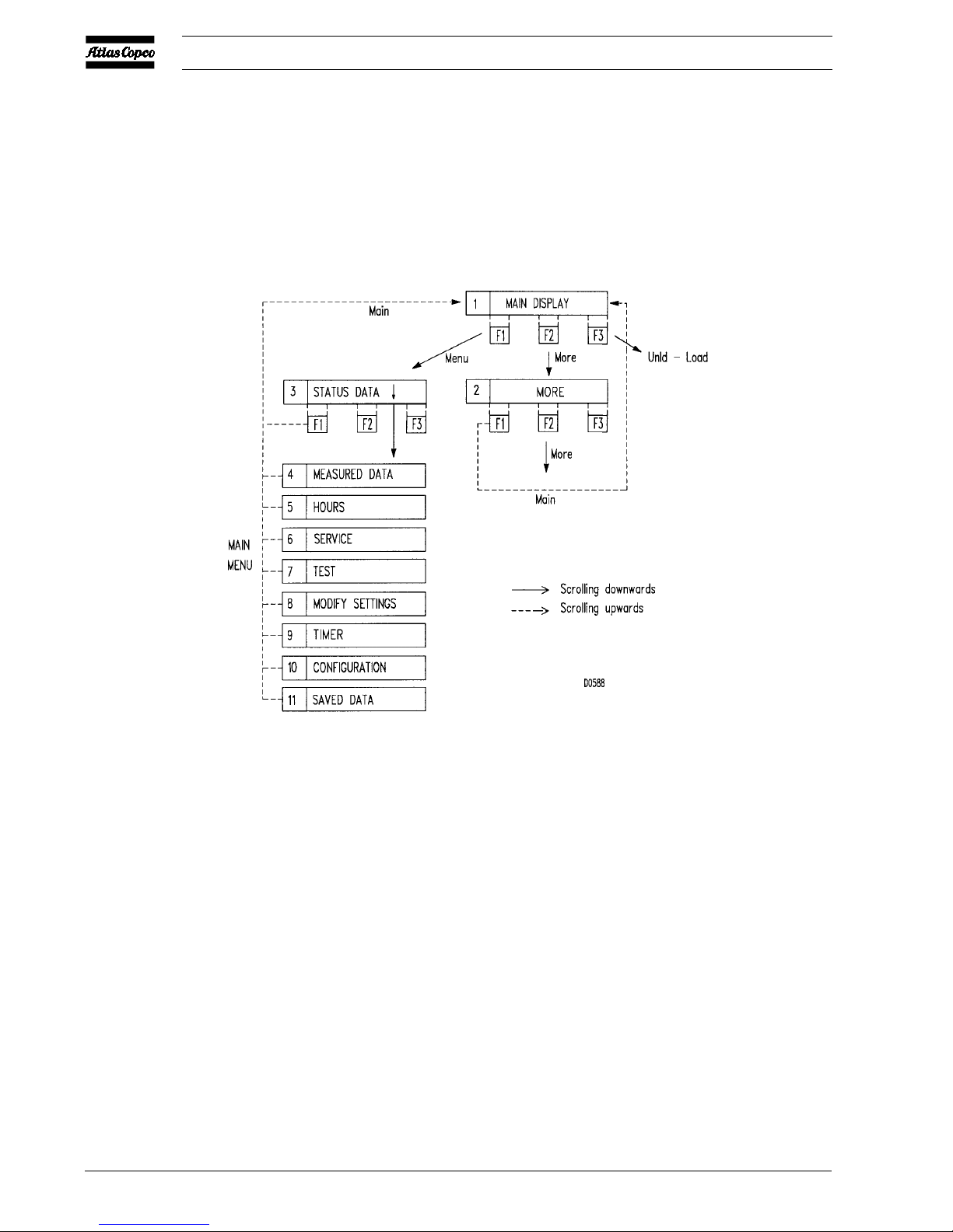
4.1 Function of control programs (Figs. 4.1
up to 4.3)
Program See Function
section
MAIN 5 Shows in short the operation status
DISPLAY of the compressor. Is the gateway
to all functions.
MAIN MENU 6 Is the gateway to other functions
via submenus.
SUBMENUS
Status data 7 Calling up the status of the
compressor protection functions
(shut-down and shut-down
warning). Resetting of a shutdown and motor overload.
Measured data 8 Calling up the actual measured
temperature at the compressor
element outlet, the dewpoint (on
compressors with integrated air
dryer) and the status of the motor
overload protection. On GA55 up
to -90C also the actual pressure
difference over the oil separator,
the status of the fan motor overload
protection and on water-cooled
compressors also the actual cooling
water outlet temperature.
Hours 9 Calling up the running hours,
loading hours, regulator hours and
number of motor starts.
Service 10 Calling up and resetting the service
messages for the oil, oil filter, oil
separator, air filter.
Test 11 Display test.
Modify settings 12 Modifying the settings for
regulation (e.g. loading and
unloading), for protection (e.g.
temperature shut-down level) and
for service (e.g. for the oil).
Timer 13 Programming the compressor
start/stop commands.
Configuration 14 Programming the time, date,
display language, units, motor start
mode and date format. On GA5
up to GA45, dewpoint tempera-
ture display mode and the
dewpoint protection.
2920 1207 05
6
User manual
Fig. 4.1. General menu flow
2920 1207 05
7
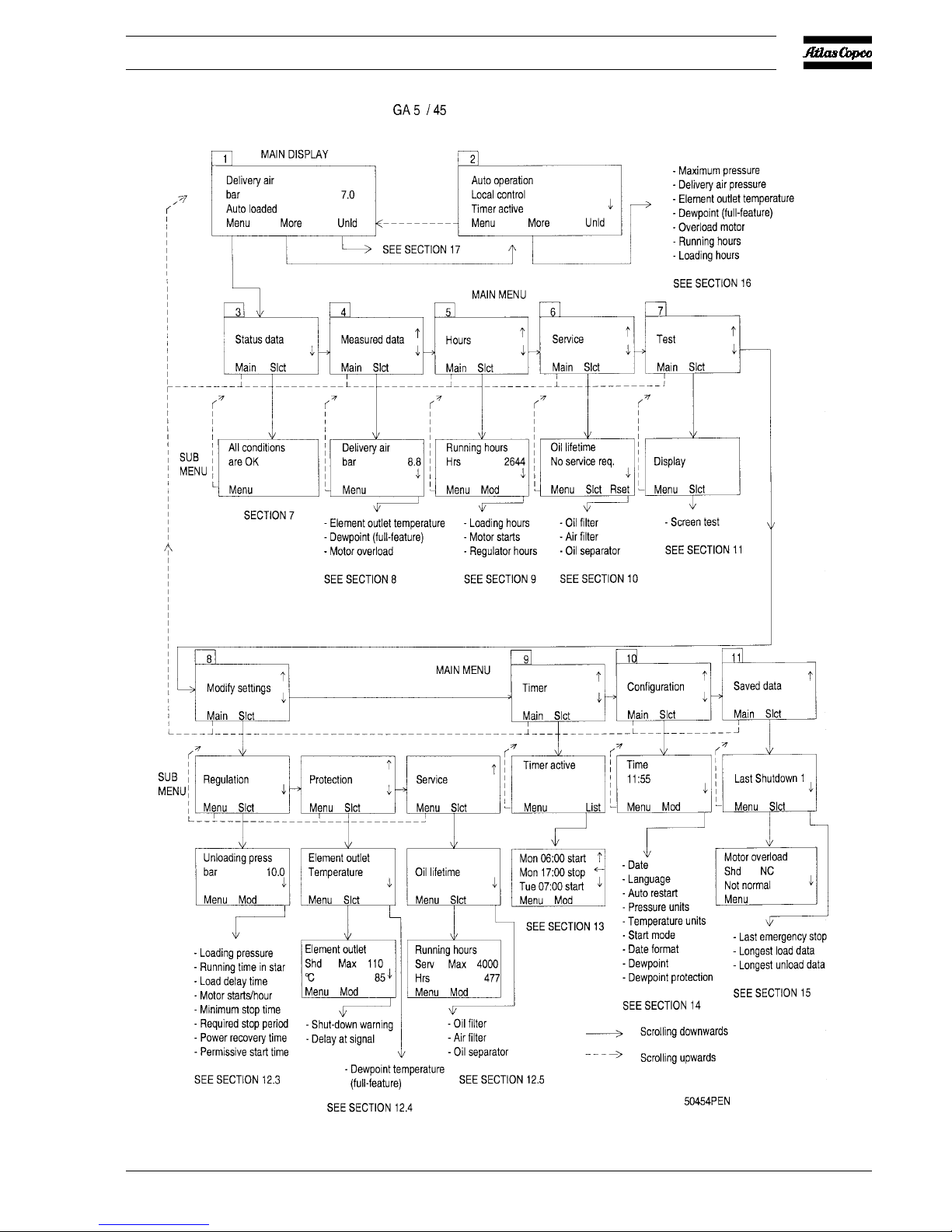
User manual
Fig. 4.2. Menu flow for regulator of GA5/45
 Loading...