

Atlas Copco GA18 VSD, GA30 VSD Instruction Book

Atlas Copco Stationary Air Compressors
GA18 VSD and GA30 VSD
Instruction Book
From serial number AII-297 500 onwards.
Important: This book must be used together with the "User manual for the Elektronikon® II regulator for
GA VSD compressors"
·
Copyright 2002, Atlas Copco Airpower n.v., Antwerp, Belgium.
Any unauthorized use or copying of the contents or any part thereof is prohibited. This applies in
particular to trademarks, model denominations, part numbers and drawings.
·
This instruction book meets the requirements for instructions specified by the machinery
directive 98/37/EC and is valid for CE as well as non-CE labelled machines.
No. 2920 1454 00
Registration code: APC G18-30 VSD/2002 / 38 / 985
2002-08
www.atlascopco.com

Instruction book
This instruction book describes how to handle the machines to ensure safe operation, optimum efficiency and long service life.
Read this book before putting the machine into operation to ensure correct handling, operation and proper maintenance from
the beginning. The maintenance schedule comprises measures for keeping the machine in good condition.
Keep the book available for the operator and make sure that the machine is operated and that maintenance is carried out
according to the instructions. Record all operating data, maintenance performed, etc. in an operator's logbook available from
Atlas Copco. Follow all relevant safety precautions, including those mentioned on the cover of this book.
Repairs must be carried out by trained personnel from Atlas Copco who can be contacted for any further information.
In all correspondence always mention the type and the serial number, shown on the data plate.
For all data not mentioned in the text, see sections "Preventive maintenance schedule" and "Principal data".
The company reserves the right to make changes without prior notice.
Contents
Page
1 Leading particulars . . . . . . . . . . . . . . . . . . . . . . . . . . 3
1.1 General description . . . . . . . . . . . . . . . . . . . . . . . . 3
1.1.1 Air flow . . . . . . . . . . . . . . . . . . . . . . . . . . . 5
1.1.2 Oil system . . . . . . . . . . . . . . . . . . . . . . . . . 5
1.1.3 Cooling and condensate drain systems . . . 6
1.2 Regulating system . . . . . . . . . . . . . . . . . . . . . . . . . 6
1.3 Elektronikon control module . . . . . . . . . . . . . . . . 6
1.3.1 Elektronikon regulator. . . . . . . . . . . . . . . . 7
1.3.2 Control panel . . . . . . . . . . . . . . . . . . . . . . . 7
1.4 Electric cabinet . . . . . . . . . . . . . . . . . . . . . . . . . . 11
1.5 Air dryer on GA Workplace Full-feature . . . . . . 12
1.5.1 Compressed air circuit. . . . . . . . . . . . . . . 12
1.5.2 Refrigeration circuit . . . . . . . . . . . . . . . . 12
2 Installation . . . . . . . . . . . . . . . . . . . . . . . . . . . . . . . . . 13
2.1 Dimension drawing. . . . . . . . . . . . . . . . . . . . . . . 13
2.2 Electric cable size . . . . . . . . . . . . . . . . . . . . . . . . 14
2.3 Installation proposal . . . . . . . . . . . . . . . . . . . . . . 14
2.4 Electrical connections. . . . . . . . . . . . . . . . . . . . . 16
3 Operating instructions . . . . . . . . . . . . . . . . . . . . . . . 16
3.1 Initial start-up . . . . . . . . . . . . . . . . . . . . . . . . . . . 16
3.2 Before starting . . . . . . . . . . . . . . . . . . . . . . . . . . 17
3.3 Starting . . . . . . . . . . . . . . . . . . . . . . . . . . . . . . . . 18
3.4 During operation . . . . . . . . . . . . . . . . . . . . . . . . . 18
3.5 Stopping . . . . . . . . . . . . . . . . . . . . . . . . . . . . . . . 19
3.6 Taking out of operation. . . . . . . . . . . . . . . . . . . . 19
4 Maintenance . . . . . . . . . . . . . . . . . . . . . . . . . . . . . . . 21
4.1 Preventive maintenance schedule for the
compressor . . . . . . . . . . . . . . . . . . . . . . . . . . . . . 21
Page
4.2 Compressor motor . . . . . . . . . . . . . . . . . . . . . . . 22
4.3 Oil and oil filter change interval . . . . . . . . . . . . . 23
4.4 Oil specifications . . . . . . . . . . . . . . . . . . . . . . . . 23
4.4.1 Atlas Copco Roto-injectfluid . . . . . . . . . 23
4.4.2 Mineral oil . . . . . . . . . . . . . . . . . . . . . . . . 23
4.5 Oil change . . . . . . . . . . . . . . . . . . . . . . . . . . . . . . 23
4.6 Oil filter change . . . . . . . . . . . . . . . . . . . . . . . . . 23
4.7 Storage after installation . . . . . . . . . . . . . . . . . . . 23
4.8 Service kits . . . . . . . . . . . . . . . . . . . . . . . . . . . . . 24
5 Adjustments and servicing procedures . . . . . . . . . . 24
5.1 Air filter . . . . . . . . . . . . . . . . . . . . . . . . . . . . . . . 24
5.1.1 Recommendations . . . . . . . . . . . . . . . . . . 24
5.1.2 Servicing . . . . . . . . . . . . . . . . . . . . . . . . . 24
5.2 Coolers . . . . . . . . . . . . . . . . . . . . . . . . . . . . . . . . 24
5.3 Safety valve . . . . . . . . . . . . . . . . . . . . . . . . . . . . . 24
6 Problem solving . . . . . . . . . . . . . . . . . . . . . . . . . . . . . 25
7 Principal data . . . . . . . . . . . . . . . . . . . . . . . . . . . . . . 26
7.1 Readings on display . . . . . . . . . . . . . . . . . . . . . . 26
7.2 Setting of safety valve. . . . . . . . . . . . . . . . . . . . . 26
7.3 Settings of circuit breakers . . . . . . . . . . . . . . . . . 26
7.4 Compressor specifications . . . . . . . . . . . . . . . . . 26
7.4.1 Reference conditions . . . . . . . . . . . . . . . . 26
7.4.2 Specific data of GA18 VSD . . . . . . . . . . 27
7.4.3 Specific data of GA30 VSD . . . . . . . . . . 27
7.5 Conversion list of SI units into US/British units 28
8 Instructions for use of air receiver . . . . . . . . . . . . . 28
2
2920 1454 00

Instruction book
1 LEADING PARTICULARS
1.1 General description
GA VSD (Variable Speed Drive) compressors are air-cooled
stationary, single-stage, oil-injected screw compressors, driven
by an electric motor.
GA Workplace (Fig. 1.1)
The compressors are enclosed in a sound-insulated bodywork.
The front panel comprises an emergency stop button (S3) and
an Elektronikon control module (E1) including the start and
stop buttons. An electric cabinet comprising fuses,
transformers, fan motor overload relay, etc. is located behind
this panel. The compressor is also provided with an automatic
condensate drain system.
GA Workplace Full-feature
GA Workplace Full-feature are additionally provided with an
air dryer (1-Fig. 1.4) which removes moisture from the
compressed air by cooling the air to near freezing point and
automatically draining the condensate.
2920 1454 00
E1 Elektronikon control module
S3 Emergency stop button
Fig. 1.1 General view of GA18 VSD
3
Instruction book
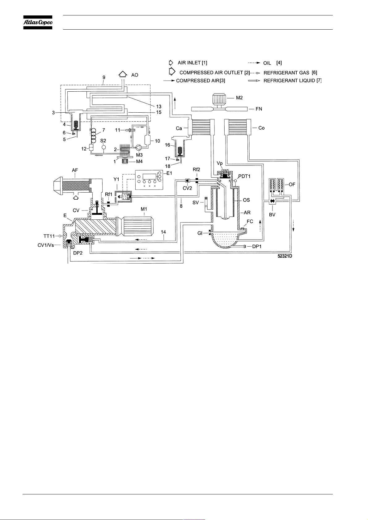
AF Air filter
AO Dry air outlet
AR Air receiver/oil separator
BV Oil cooler by-pass valve
Ca Air cooler
Co Oil cooler
CV Check valve
CV1/Vs Check valve/oil stop valve
CV2 Non-return valve
DP1 Oil drain plug, air receiver
DP2 Oil drain plug, check valve/
oil stop valve
E Compressor element
E1 Elektronikon control module
FC Oil filler plug
FN Fan, compressor coolers
Gl Oil level gauge
M1 Compressor motor
M2 Fan motor, compressor
coolers
4
M3 Refrigerant compressor
M4 Condenser fan motor
OF Oil filter
OS Oil separator element
PDT1 Differential pressure sensor,
oil separator
Rf1 Nozzle
Rf2 Restrictor
SV Safety valve
S2 Fan control switch
TT11 Temperature sensor,
compressor element outlet
Vp Minimum pressure valve
Y1 Solenoid valve, blow off
1 Condenser cooling fan
2 Refrigerant condenser
3 Condensate separator
4 Condensate trap, dryer
5 Automatic condensate drain
hose
Fig. 1.2 Flow diagram
6 Manual condensate drain
valve
7 Capillary tube
8 Blow-off air flexible
9 Insulating block
10 Accumulator
11 Hot gas by-pass valve
12 Liquid refrigerant dryer/
filter
13 Air/air heat exchanger
14 Oil scavenging line
15 Air/refrigerant heat
exchanger/evaporator
16 Condensate trap, air cooler
17 Manual condensate drain
valve
18 Automatic condensate drain
valve
2920 1454 00
Instruction book
1.1.1 Air flow (Fig. 1.2)
Air drawn through filter (AF) and check valve (CV) into
compressor element (E) is compressed. Compressed air and
oil flow into air receiver/oil separator (AR). The air is
discharged through the outlet valve via minimum pressure
valve (Vp), air cooler (Ca) and condensate trap (4).
Minimum pressure valve (Vp) prevents the receiver pressure
from dropping below a minimum pressure and includes a check
valve which prevents blow-back of compressed air from the
air net.
1.1.2 Oil system (Fig. 1.2)
In air receiver/oil separator (AR), most of the oil is removed
from the air/oil mixture centrifugally. The balance is removed
by oil separator element (OS). The oil collects in the lower
part of air receiver/oil separator (AR), which serves as oil
tank.
The oil system is provided with a by-pass valve (BV). When
the oil temperature is below 60 degrees Celsius, by-pass valve
(BV) shuts off the oil supply from oil cooler (Co). Air pressure
forces the oil from air receiver/oil separator (AR) through oil
filter (OF) and oil stop valve (Vs) to compressor element (E)
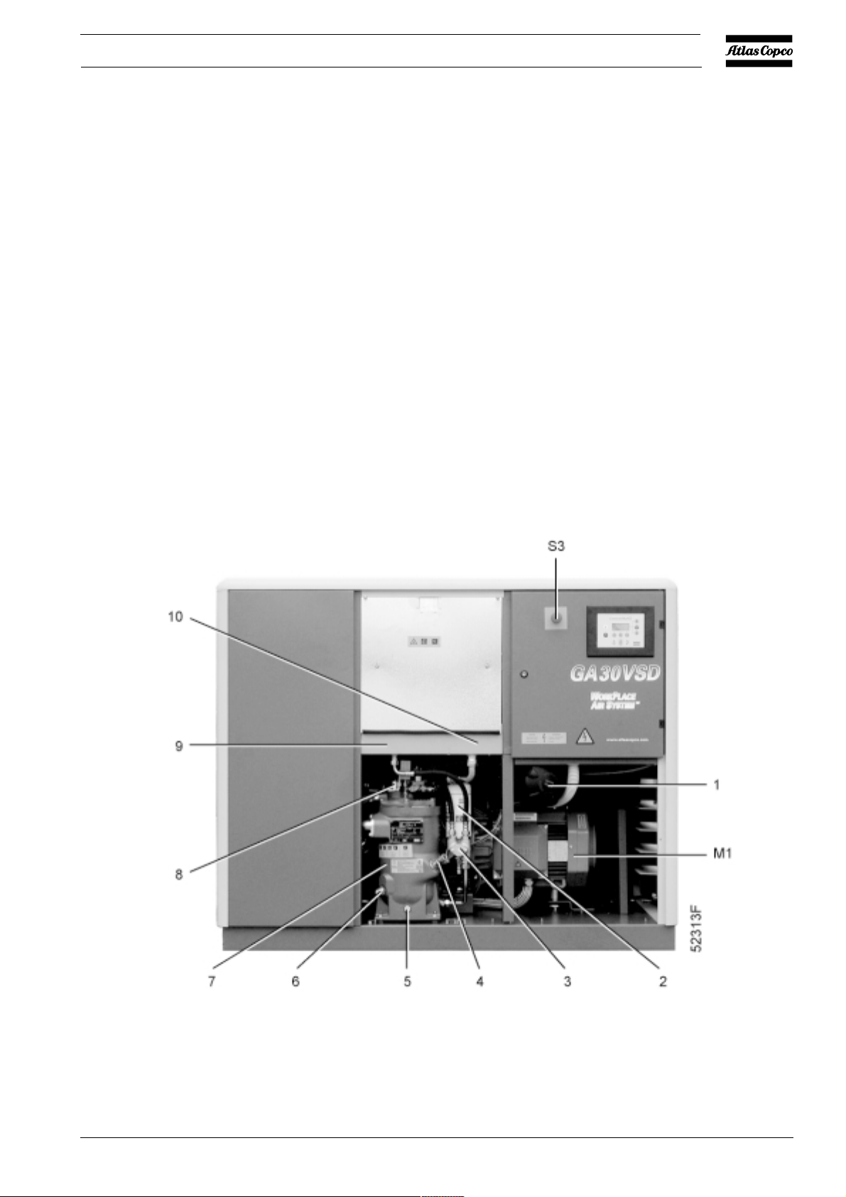
and its lubrication points. Oil cooler (Co) is by-passed.
1 Air filter
2 Oil filter
3 By-pass valve, oil cooler
4 Oil filler plug
2920 1454 00
5 Oil drain plug, air receiver
6 Oil level gauge
7 Air receiver/oil separator
8 Minimum pressure valve
Fig. 1.3 Front view of GA18 VSD
9 Air cooler
10 Oil cooler
M1 Compressor motor
S3 Emergency stop button
5

Instruction book
By-pass valve (BV) starts opening the oil supply from cooler
(Co) when the oil temperature has increased to 60 degrees
Celsius. At approx. 75 degrees Celsius all the oil flows through
the oil cooler.
1.1.3 Cooling and condensate drain systems (Fig.
1.4)
The cooling system comprises air cooler (2) and oil cooler
(6). The compressors are air-cooled; the cooling air is
generated by fan (3).
A condensate trap (12) is provided in the air outlet system.
Full-feature compressors have an extra condensate trap on the
integrated dryer. Each trap is equipped with a valve for
automatic condensate draining during operation (2 and 5-Fig.
1.5) and a manually operated valve (1 and 4-Fig. 1.5) for
draining after stopping the compressor.
1.2 Regulating system
If the air consumption is less than the air output of the
compressor, the net pressure increases. When the net pressure
is higher than the setpoint (desired net pressure), the regulator
will decrease the motor speed. If the net pressure keeps on
rising when the motor runs at minimum speed, the regulator
will stop the motor. If the motor is stopped automatically and
the net pressure approaches the setpoint, the regulator will
restart the motor.
1.3 Elektronikon control module
The control module consists of an Elektronikon regulator and
a control panel.
1 Dryer
2 Air cooler
3 Fan, compressor coolers
4 Fan motor
5 Vent plug, oil cooler
6
6 Oil cooler
7 Check valve, air inlet
8 Oil drain plug
9 Check valve/oil stop valve
10 Compressor element
Fig. 1.4 Rear view of GA18 VSD
11 Arrow, rotation direction
12 Condensate trap
M1 Compressor motor
2920 1454 00
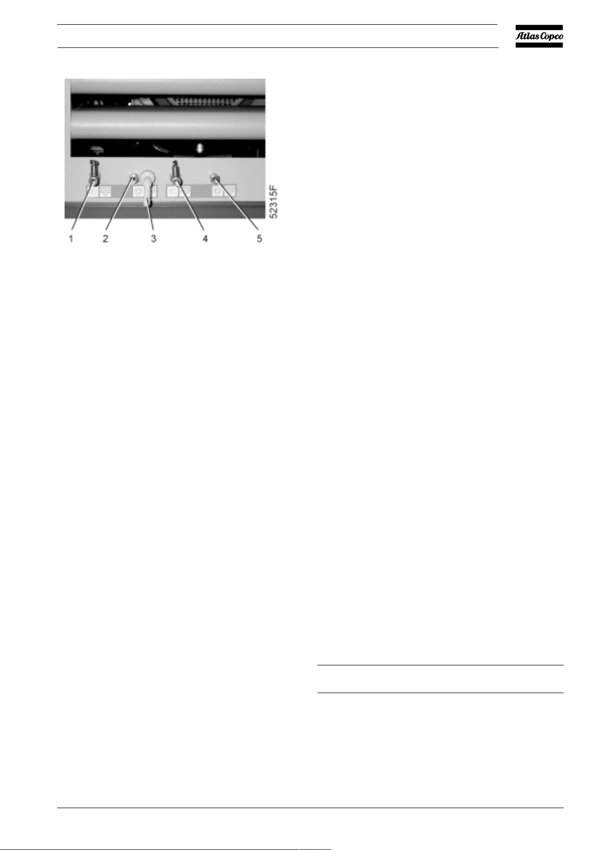
Instruction book
1 Manual condensate drain, dryer condensate trap
2 Automatic condensate drain, dryer condensate trap
3 Condensate outlet, optional OSD
4 Manual condensate drain, air cooler condensate trap
5 Automatic condensate drain, air cooler condensate trap
Fig. 1.5 Condensate outlets
Protecting the compressor
If the compressor element outlet temperature exceeds the
programmed shut-down level, the compressor will be stopped.
This will be indicated on the control panel (Fig. 1.7). The
compressor will also be stopped in case of overload of fan
motor (4-Fig. 1.4).
If the compressor element outlet temperature exceeds a
programmed value below the shut-down level, this will also
be indicated to warn the operator before the shut-down level
is reached.
Service plans
A number of service operations are grouped in plans (called
Service plans A, B and C). Each Service plan has a
programmed time interval. If a time interval is exceeded, a
message will appear on display (12-Fig. 1.7) to warn the
operator to carry out the service actions belonging to that plan.
See section 4.1.
Automatic restart after voltage failure
For compressors leaving the factory, this function is made
inactive. If desired, the function can be activated. Consult
Atlas Copco.
1.3.1 Elektronikon regulator (E1-Fig. 1.1)
The regulator has following functions:
Controlling the compressor
The regulator matches the compressor output to the air
consumption by speed regulation of the motor.
The regulator stops the compressor whenever necessary:
- Indirect stop: i.e. the compressor runs at minimum speed
and the net pressure rises to the indirect stop level
- Direct stop: i.e. the compressor runs at a speed in between
minimum and maximum and the net pressure rises above
the direct stop setpoint.
Warning If activated and provided the module was in the
automatic operation mode, the compressor will
automatically restart if the supply voltage to the
module is restored within a programmed time
period.
The power recovery time (the period within which
the voltage must be restored to have an automatic
restart) can be set between 10 and 3600 seconds
or to Infinite. If the power recovery time is set to
Infinite, the compressor will always restart after
a voltage failure, no matter how long it takes to
restore the voltage. A restart delay can also be
programmed, allowing e.g. two compressors to
be restarted one after the other.
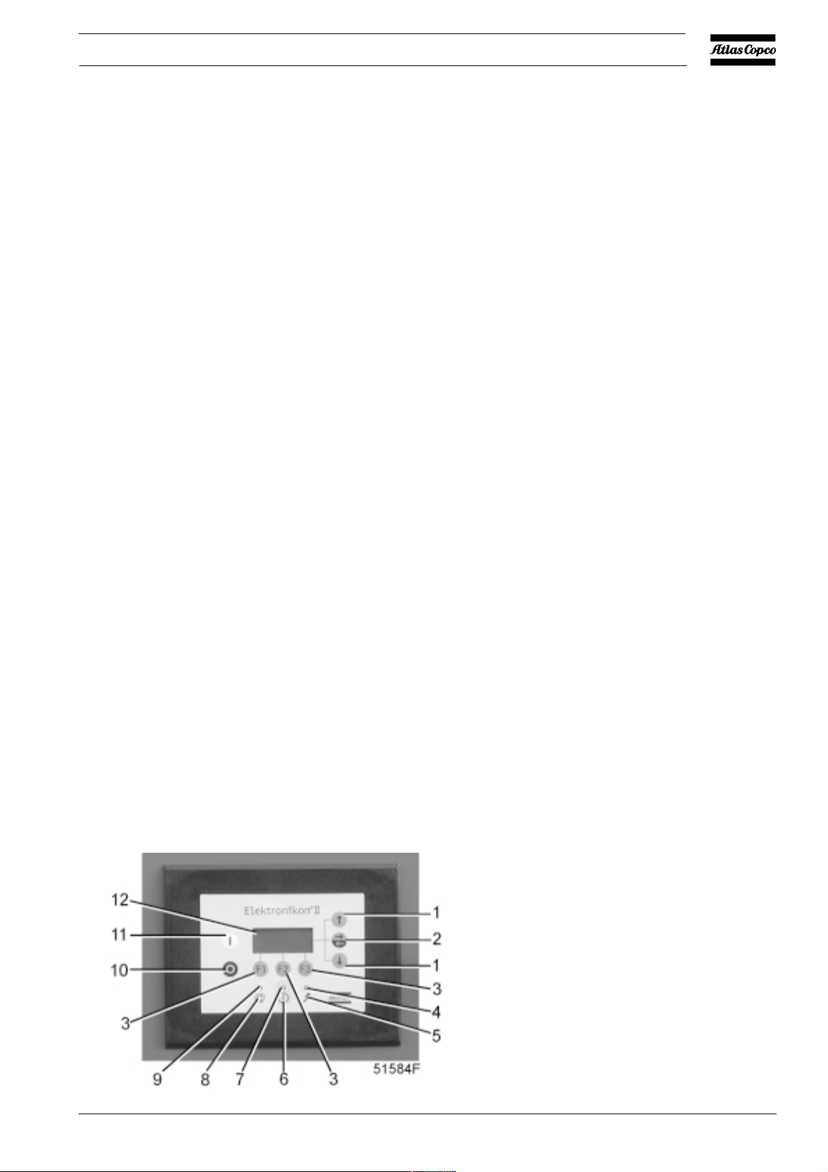
1.3.2 Control panel (Figs. 1.1 and 1.7)
LEDs/buttons/keys
Ref. Designation Function
Both settings are programmable; consult the "User manual
for Elektronikon regulator", section "Modify settings
submenu".
Note: to prevent the safety valve from opening too frequently
on 13 bar compressors, the setting of the direct stop setpoint
should never be more than 1 bar.
2920 1454 00
1 Scroll keys Keys to scroll through the display.
2 Tabulator key Key to select the parameter
indicated by a horizontal arrow.
Only the parameters followed by
an arrow pointing to the right are
accessible for modifying.
7
Instruction book
8
2920 1454 00
Instruction book
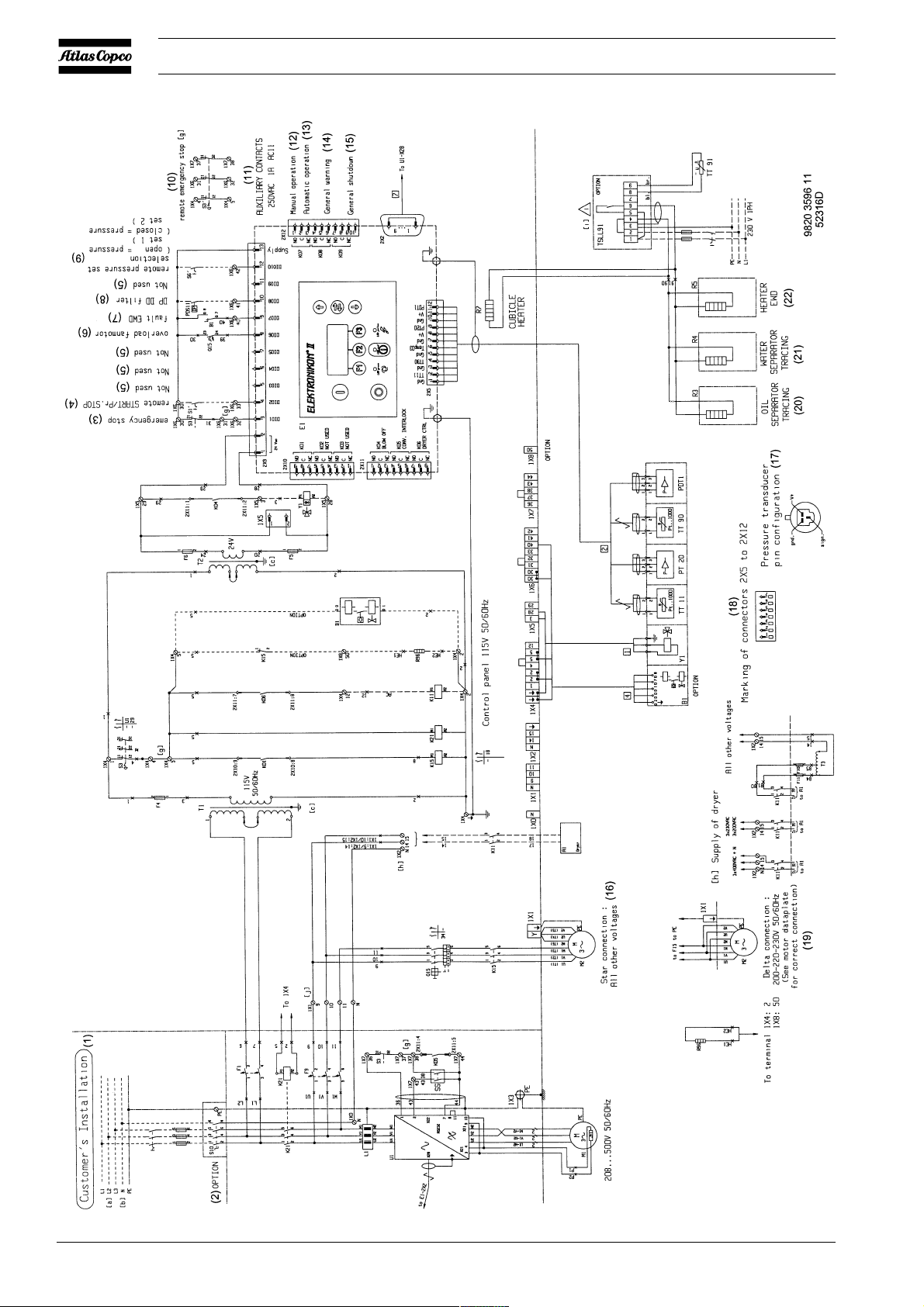
COMPRESSOR
A1 Dryer (optional)
B1 Optional electronic
condensate drain
PDS11 Delta P switch, integrated
dryer (optional)
PDT1 Differential pressure sensor,
oil separator
PT20 Pressure sensor, air outlet
R3,4,5 Freeze protection (optional)
R7 Heater cubicle (optional)
R96 Anti-condensation heater
(optional)
TSLL91 Thermostat, freeze
protection (optional)
TT11 Temperature sensor,
compressor element outlet
TT90 Temperature sensor,
dewpoint
TT91 Temperature sensor,
converter cubicle (optional)
Y1 Solenoid valve, blow-off
MOTORS
M1 Compressor motor
M2 Fan motor, compressor
coolers
ELECTRIC CABINET
E1 Elektronikon control module
F4/5/6 Fuses
K11 Contactor, dryer
K15 Contactor, fan motor
S3 Emergency stop button
S5 Service switch
S10 Main power isolating switch
(optional)
T1/T2 Transformer
T3 Transformer
Q15 Circuit breaker, fan motor
CONVERTER CABINET
F1/2 Fuses
F9 Circuit breaker
K21 Line contactor
Fig. 1.6 Electrical diagram
U1 Frequency converter
Z1 EMC filter
CONTROL MODULE (E1)
I Start button
K01 Auxiliary relay, fan motor
K02 Auxiliary relay
K03 Auxiliary relay
K04 Auxiliary relay, solenoid
valve
K05 Auxiliary relay, converter
shut-down
K06 Auxiliary relay, dryer
K07 Auxiliary relay, manual/
automatic operation
K08 Auxiliary relay, general
warning
K09 Auxiliary relay, general
shut-down
O Stop button
2920 1454 00
1 Scroll keys
2 Tabulator key
3 Function keys
4 LED, voltage on
5 Pictograph, voltage on
6 Pictograph, alarm
7 LED, general alarm
8 Pictograph, automatic operation
9 LED, automatic operation
10 Stop button
11 Start button
12 Display
Fig. 1.7 Control panel
9
 Loading...