

Atlas Copco GA 160 VSD Instruction Book

GA 160 VSD
APF192090
Instruction book


Atlas Copco
GA 160 VSD
APF192090
Instruction book
Original instructions
2014 - 10
Manufacturing Date: 11/04/2014
Copyright Notice
Any unauthorized use or copying of the contents or any part thereof is prohibited.
This applies in particular to trademarks, model denominations, part numbers and drawings.
This instruction book is valid for CE as well as non-CE labelled machines. It meets the
requirements for instructions specified by the applicable European directives as identified
in the Declaration of Conformity.
www.atlascopco.com

Instruction book
Table of contents
1 Safety precautions..........................................................................................................6
1.1 SAFETY ICONS...................................................................................................................................6
1.2 GENERAL SAFETY PRECAUTIONS............................................................................................................6
1.3 SAFETY PRECAUTIONS DURING INSTALLATION...........................................................................................7
1.4 SAFETY PRECAUTIONS DURING OPERATION..............................................................................................8
1.5 SAFETY PRECAUTIONS DURING MAINTENANCE OR REPAIR...........................................................................9
2 General description......................................................................................................11
2.1 INTRODUCTION.................................................................................................................................11
2.2 AIR AND OIL SYSTEM.........................................................................................................................12
2.3 COOLING AND CONDENSATE SYSTEM....................................................................................................16
3 Elektronikon regulator.................................................................................................17
3.1 ELEKTRONIKON CONTROL SYSTEM.......................................................................................................17
3.2 CONTROL PANEL..............................................................................................................................19
3.3 FUNCTION KEYS...............................................................................................................................20
3.4 SCROLL KEYS..................................................................................................................................21
3.5 EMERGENCY STOP BUTTON................................................................................................................22
3.6 CONTROL PROGRAMS........................................................................................................................22
3.7 CALLING UP MENUS..........................................................................................................................24
3.8 MAIN SCREEN MENU.........................................................................................................................25
3.9 STATUS DATA MENU..........................................................................................................................26
3.10 MEASURED DATA MENU.....................................................................................................................29
3.11 COUNTERS MENU.............................................................................................................................30
3.12 TEST MENU.....................................................................................................................................31
3.13 MODIFY PARAMETERS.......................................................................................................................31
3.14 MODIFYING COMPRESSOR/MOTOR SETTINGS..........................................................................................32
3.15 FAN MOTOR SETTINGS.......................................................................................................................33
2 APF192090

Instruction book
3.16 MODIFYING PARAMETERS...................................................................................................................34
3.17 MODIFYING PROTECTION SETTINGS......................................................................................................35
3.18 MODIFYING SERVICE PLANS................................................................................................................36
3.19 PROGRAMMING CLOCK FUNCTION.........................................................................................................37
3.20 MODIFYING CONFIGURATION SETTINGS..................................................................................................41
3.21 SERVICE MENU................................................................................................................................43
3.22 SAVED DATA MENU...........................................................................................................................45
3.23 PROGRAMMABLE SETTINGS.................................................................................................................45
4 Installation.....................................................................................................................49
4.1 DIMENSION DRAWING........................................................................................................................49
4.2 INSTALLATION PROPOSAL...................................................................................................................51
4.3 ELECTRIC CABLE SIZE AND FUSES........................................................................................................54
4.4 ELECTRIC CONNECTIONS....................................................................................................................55
4.5 QUALITY OF SAFETY COMPONENTS.......................................................................................................63
4.6 INSTALLATION INSTRUCTIONS FOR CUBICLE FAN......................................................................................63
4.7 INSTALLATION INSTRUCTIONS FOR HEAVY DUTY FILTER FOR VSD CUBICLE..................................................66
4.8 INSTALLATION INSTRUCTIONS FOR DRYER BY-PASS .................................................................................69
4.9 INSTALLATION INSTRUCTIONS GSM ALARM............................................................................................71
4.10 PICTOGRAPHS.................................................................................................................................74
5 Operating instructions.................................................................................................76
5.1 INITIAL START-UP..............................................................................................................................76
5.2 BEFORE STARTING............................................................................................................................78
5.3 STARTING.......................................................................................................................................78
5.4 DURING OPERATION..........................................................................................................................79
5.5 CHECKING THE DISPLAY.....................................................................................................................79
5.6 STOPPING.......................................................................................................................................81
5.7 TAKING OUT OF OPERATION................................................................................................................81
5.8 USE OF AIR RECEIVER.......................................................................................................................82
APF192090 3

Instruction book
6 Maintenance..................................................................................................................83
6.1 PREVENTIVE MAINTENANCE SCHEDULE..................................................................................................83
6.2 MOTORS.........................................................................................................................................84
6.3 OIL SPECIFICATIONS..........................................................................................................................85
6.4 OIL CHANGE....................................................................................................................................85
6.5 STORAGE AFTER INSTALLATION...........................................................................................................89
6.6 SERVICE KITS..................................................................................................................................89
7 DD filter..........................................................................................................................91
7.1 MAINTENANCE.................................................................................................................................91
7.2 SERVICE INTERVALS..........................................................................................................................91
7.3 FILTER ELEMENT CHANGE ..................................................................................................................91
7.4 FILTER DISPOSAL..............................................................................................................................92
7.5 REFERENCE CONDITIONS...................................................................................................................92
7.6 PRINCIPAL DATA...............................................................................................................................92
8 Integrated dryer............................................................................................................93
8.1 CONDENSATE DRAIN SYSTEM..............................................................................................................93
8.2 MAINTENANCE INSTRUCTIONS.............................................................................................................94
8.3 PROBLEM SOLVING...........................................................................................................................95
9 Adjustments and servicing procedures.....................................................................96
9.1 AIR FILTERS....................................................................................................................................96
9.2 COOLERS.......................................................................................................................................98
9.3 SAFETY VALVE...............................................................................................................................100
10 Problem solving..........................................................................................................101
10.1 PROBLEM SOLVING.........................................................................................................................101
11 Technical data.............................................................................................................103
4 APF192090

Instruction book
11.1 READINGS ON DISPLAY....................................................................................................................103
11.2 REFERENCE CONDITIONS.................................................................................................................104
11.3 LIMITS..........................................................................................................................................104
11.4 SETTINGS OF SAFETY VALVE.............................................................................................................104
11.5 SETTINGS OF CIRCUIT BREAKERS.......................................................................................................104
11.6 COMPRESSOR DATA........................................................................................................................105
12 Pressure equipment directives.................................................................................106
13 Documentation............................................................................................................108
APF192090 5
1 Safety precautions
1.1 Safety icons
Explanation
Danger for life
Warning
Important note
Instruction book
1.2 General safety precautions
1. The operator must employ safe working practices and observe all related work safety requirements and
regulations.
2. If any of the following statements does not comply with the applicable legislation, the stricter of the two
shall apply.
3. Installation, operation, maintenance and repair work must only be performed by authorized, trained,
specialized personnel. The personnel should apply safe working practices by use of personal protection
equipment, appropriate tools and defined procedures.
4. The compressor is not considered capable of producing air of breathing quality. For air of breathing quality,
the compressed air must be adequately purified according to the applicable legislation and standards.
5. Before any maintenance, repair work, adjustment or any other non-routine checks:
• Stop the compressor
• Press the emergency stop button
• Switch off the voltage
• Depressurize the compressor
• Lock Out - Tag Out (LOTO):
• Open the power isolating switch and lock it with a personal lock
• Tag the power isolating switch with the name of the service technician.
• On units powered by a frequency converter, wait 10 minutes before starting any electrical repair.
• Never rely on indicator lamps or electrical door locks before maintenance work, always disconnect
and check with measuring device.
If the machine is equipped with an automatic restart after voltage failure function and if this
function is active, be aware that the machine will restart automatically when the power is
restored if it was running when the power was interrupted!
6. Never play with compressed air. Do not apply the air to your skin or direct an air stream at people. Never
use the air to clean dirt from your clothes. When using the air to clean equipment, do so with extreme
caution and wear eye protection.
7. The owner is responsible for maintaining the unit in safe operating condition. Parts and accessories shall
be replaced if unsuitable for safe operation.
8. It is prohibited to walk or stand on the unit or on its components.
6 APF192090

Instruction book
1.3 Safety precautions during installation
All responsibility for any damage or injury resulting from neglecting these precautions, or
non observance of the normal caution and care required for installation, operation,
maintenance and repair, even if not expressly stated, will be disclaimed by the
manufacturer.
Precautions during installation
1. The machine must only be lifted using suitable equipment in accordance with the applicable safety
regulations. Loose or pivoting parts must be securely fastened before lifting. It is strictly forbidden to
dwell or stay in the risk zone under a lifted load. Lifting acceleration and deceleration must be kept within
safe limits. Wear a safety helmet when working in the area of overhead or lifting equipment.
2. The unit is designed for indoor use. If the unit is installed outdoors, special precautions must be taken;
consult your supplier.
3. In case the device is a compressor, place the machine where the ambient air is as cool and clean as possible.
If necessary, install a suction duct. Never obstruct the air inlet. Care must be taken to minimize the entry
of moisture at the inlet air.
4. Any blanking flanges, plugs, caps and desiccant bags must be removed before connecting the pipes.
5. Air hoses must be of correct size and suitable for the working pressure. Never use frayed, damaged or
worn hoses. Distribution pipes and connections must be of the correct size and suitable for the working
pressure.
6. In case the device is a compressor, the aspirated air must be free of flammable fumes, vapors and particles,
e.g. paint solvents, that can lead to internal fire or explosion.
7. In case the device is a compressor, arrange the air intake so that loose clothing worn by people cannot be
drawn in.
8. Ensure that the discharge pipe from the compressor to the aftercooler or air net is free to expand under
heat and that it is not in contact with or close to flammable materials.
9. No external force may be exerted on the air outlet valve; the connected pipe must be free of strain.
10. If remote control is installed, the machine must bear a clear sign stating: DANGER: This machine is
remotely controlled and may start without warning.
The operator has to make sure that the machine is stopped and depressurized and that the electrical isolating
switch is open, locked and labelled with a temporary warning before any maintenance or repair. As a
further safeguard, persons switching on or off remotely controlled machines shall take adequate
precautions to ensure that there is no one checking or working on the machine. To this end, a suitable
notice shall be affixed to the start equipment.
11. Air-cooled machines must be installed in such a way that an adequate flow of cooling air is available and
that the exhausted air does not recirculate to the compressor air inlet or cooling air inlet.
12. The electrical connections must correspond to the applicable codes. The machines must be earthed and
protected against short circuits by fuses in all phases. A lockable power isolating switch must be installed
near the compressor.
13. On machines with automatic start/stop system or if the automatic restart function after voltage failure is
activated, a sign stating "This machine may start without warning" must be affixed near the instrument
panel.
14. In multiple compressor systems, manual valves must be installed to isolate each compressor. Non-return
valves (check valves) must not be relied upon for isolating pressure systems.
15. Never remove or tamper with the safety devices, guards or insulation fitted on the machine. Every pressure
vessel or auxiliary installed outside the machine to contain air above atmospheric pressure must be
protected by a pressure relieving device or devices as required.
APF192090 7

Instruction book
16. Piping or other parts with a temperature in excess of 70˚C (158˚F) and which may be accidentally touched
by personnel in normal operation must be guarded or insulated. Other high temperature piping must be
clearly marked.
17. For water-cooled machines, the cooling water system installed outside the machine has to be protected by
a safety device with set pressure according to the maximum cooling water inlet pressure.
18. If the ground is not level or can be subject to variable inclination, consult the manufacturer.
19. If the device is a dryer and no free extinguishing system is present in the air net close to the dryer, safety
valves must be installed in the vessels of the dryer.
Also consult following safety precautions: Safety precautions during operation and Safety
precautions during maintenance.
These precautions apply to machinery processing or consuming air or inert gas.
Processing of any other gas requires additional safety precautions typical to the application
which are not included herein.
Some precautions are general and cover several machine types and equipment; hence
some statements may not apply to your machine.
1.4 Safety precautions during operation
All responsibility for any damage or injury resulting from neglecting these precautions, or
non observance of the normal caution and care required for installation, operation,
maintenance and repair, even if not expressly stated, will be disclaimed by the
manufacturer.
Precautions during operation
1. Never touch any piping or components of the machine during operation.
2. Use only the correct type and size of hose end fittings and connections. When blowing through a hose or
air line, ensure that the open end is held securely. A free end will whip and may cause injury. Make sure
that a hose is fully depressurized before disconnecting it.
3. Persons switching on remotely controlled machines shall take adequate precautions to ensure that there
is no one checking or working on the machine. To this end, a suitable notice shall be affixed to the remote
start equipment.
4. Never operate the machine when there is a possibility of taking in flammable or toxic fumes, vapors or
particles.
5. Never operate the machine below or in excess of its limit ratings.
6. Keep all bodywork doors shut during operation. The doors may be opened for short periods only, e.g. to
carry out routine checks. Wear ear protectors when opening a door.
On machines without bodywork, wear ear protection in the vicinity of the machine.
7. People staying in environments or rooms where the sound pressure level reaches or exceeds 80 dB(A)
shall wear ear protectors.
8. Periodically check that:
• All guards are in place and securely fastened
• All hoses and/or pipes inside the machine are in good condition, secure and not rubbing
• No leaks occur
• All fasteners are tight
• All electrical leads are secure and in good order
• Safety valves and other pressure relief devices are not obstructed by dirt or paint
• Air outlet valve and air net, i.e. pipes, couplings, manifolds, valves, hoses, etc. are in good repair, free
of wear or abuse
8 APF192090
Instruction book
• Air cooling filters of the electrical cabinet are not clogged
9. If warm cooling air from compressors is used in air heating systems, e.g. to warm up a workroom, take
precautions against air pollution and possible contamination of the breathing air.
10. On water-cooled compressors using open circuit cooling towers, protective measures must be taken to
avoid the growth of harmful bacteria such as Legionella pneumophila bacteria.
11. Do not remove any of, or tamper with, the sound-damping material.
12. Never remove or tamper with the safety devices, guards or insulations fitted on the machine. Every pressure
vessel or auxiliary installed outside the machine to contain air above atmospheric pressure shall be
protected by a pressure relieving device or devices as required.
13. Yearly inspect the air receiver. Minimum wall thickness as specified in the instruction book must be
respected. Local regulations remain applicable if they are more strict.
Also consult following safety precautions: Safety precautions during installation and Safety
precautions during maintenance.
These precautions apply to machinery processing or consuming air or inert gas.
Processing of any other gas requires additional safety precautions typical to the application
which are not included herein.
Some precautions are general and cover several machine types and equipment; hence
some statements may not apply to your machine.
1.5 Safety precautions during maintenance or repair
All responsibility for any damage or injury resulting from neglecting these precautions, or
non observance of the normal caution and care required for installation, operation,
maintenance and repair, even if not expressly stated, will be disclaimed by the
manufacturer.
Precautions during maintenance or repair
1. Always use the correct safety equipment (such as safety glasses, gloves, safety shoes, etc.).
2. Use only the correct tools for maintenance and repair work.
3. Use only genuine spare parts for maintenance or repair. The manufacturer will disclaim all damage or
injuries caused by the use of non-genuine spare parts.
4. All maintenance work shall only be undertaken when the machine has cooled down.
5. A warning sign bearing a legend such as "Work in progress; do not start" shall be attached to the starting
equipment.
6. Persons switching on remotely controlled machines shall take adequate precautions to ensure that there
is no one checking or working on the machine. To this end, a suitable notice shall be affixed to the remote
start equipment.
7. Close the compressor air outlet valve and depressurize the compressor before connecting or disconnecting
a pipe.
8. Before removing any pressurized component, effectively isolate the machine from all sources of pressure
and relieve the entire system of pressure.
9. Never use flammable solvents or carbon tetrachloride for cleaning parts. Take safety precautions against
toxic vapors of cleaning liquids.
10. Scrupulously observe cleanliness during maintenance and repair. Keep dirt away by covering the parts
and exposed openings with a clean cloth, paper or tape.
11. Never weld or perform any operation involving heat near the oil system. Oil tanks must be completely
purged, e.g. by steam cleaning, before carrying out such operations. Never weld on, or in any way modify,
pressure vessels.
APF192090 9
Instruction book
12. Whenever there is an indication or any suspicion that an internal part of a machine is overheated, the
machine shall be stopped but no inspection covers shall be opened before sufficient cooling time has
elapsed; this to avoid the risk of spontaneous ignition of the oil vapor when air is admitted.
13. Never use a light source with open flame for inspecting the interior of a machine, pressure vessel, etc.
14. Make sure that no tools, loose parts or rags are left in or on the machine.
15. All regulating and safety devices shall be maintained with due care to ensure that they function properly.
They may not be put out of action.
16. Before clearing the machine for use after maintenance or overhaul, check that operating pressures,
temperatures and time settings are correct. Check that all control and shut-down devices are fitted and that
they function correctly. If removed, check that the coupling guard of the compressor drive shaft has been
reinstalled.
17. Every time the separator element is renewed, examine the discharge pipe and the inside of the oil separator
vessel for carbon deposits; if excessive, the deposits should be removed.
18. Protect the motor, air filter, electrical and regulating components, etc. to prevent moisture from entering
them, e.g. when steam cleaning.
19. Make sure that all sound-damping material and vibration dampers, e.g. damping material on the bodywork
and in the air inlet and outlet systems of the compressor, is in good condition. If damaged, replace it by
genuine material from the manufacturer to prevent the sound pressure level from increasing.
20. Never use caustic solvents which can damage materials of the air net, e.g. polycarbonate bowls.
21. Only if applicable, the following safety precautions are stressed when handling refrigerant:
• Never inhale refrigerant vapors. Check that the working area is adequately ventilated; if required, use
breathing protection.
• Always wear special gloves. In case of refrigerant contact with the skin, rinse the skin with water. If
liquid refrigerant contacts the skin through clothing, never tear off or remove the latter; flush
abundantly with fresh water over the clothing until all refrigerant is flushed away; then seek medical
first aid.
Also consult following safety precautions: Safety precautions during installation and Safety
precautions during operation.
These precautions apply to machinery processing or consuming air or inert gas.
Processing of any other gas requires additional safety precautions typical to the application
which are not included herein.
Some precautions are general and cover several machine types and equipment; hence
some statements may not apply to your machine.
10 APF192090
Instruction book
2 General description
2.1 Introduction
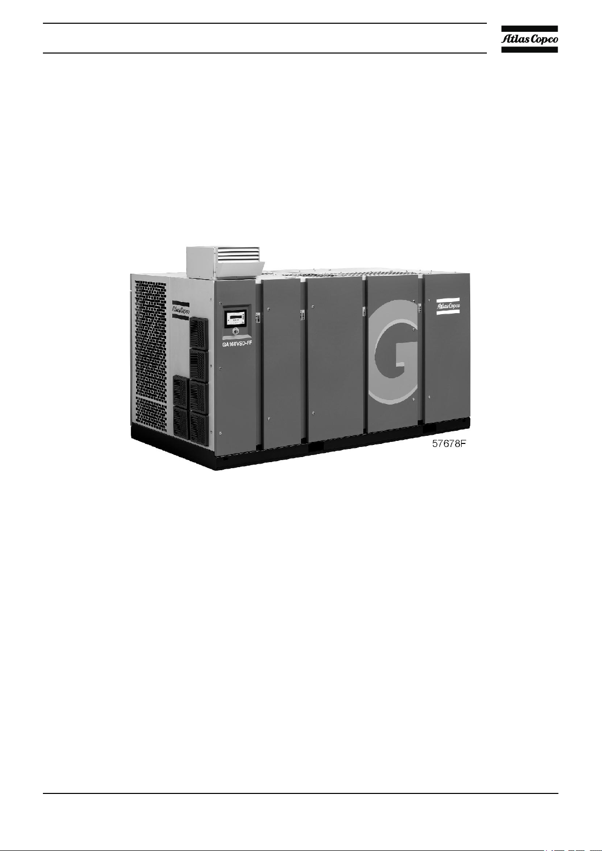
General view
Description of GA VSD compressors
GA VSD (Variable Speed Drive) compressors are single-stage, oil-injected screw compressors directly driven
by an electric motor. The compressors deliver pulsation-free air. By continuously matching the speed of the
drive motor to the air net pressure, the compressor optimizes energy consumption and reduces the operating
pressure band.
GA VSD compressors are air-cooled.
Pipe connections
NPT connections.
Roto-Xtend Duty Fluid
Roto-Xtend Duty Fluid is a special, long-life lubricant for GA oil-injected screw compressors. It provides
better cooling and extends the oil change interval.
General view of GA VSD
APF192090 11

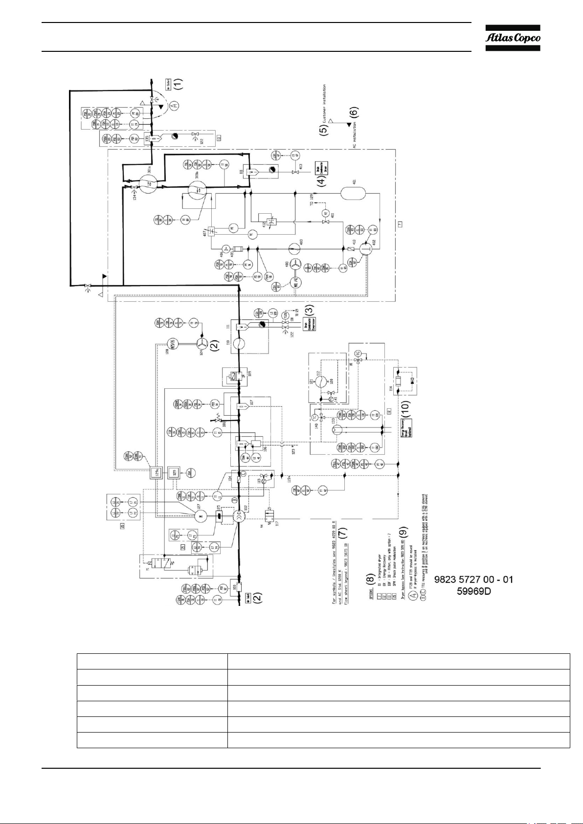
2.2 Air and oil system
Flow diagrams
Instruction book
Flow diagram for air-cooled GA VSD compressors (Energy recovery model year 2007)
12 APF192090
Instruction book
Flow diagram for air-cooled GA VSD compressors (Energy recovery model year 2014)
Drawing Reference Description
In parentheses
(1) Air outlet
(2) Air inlet
(3) Condensate drain of the compressor
(4) Condensate drain of the dryer
APF192090 13
Drawing Reference Description
(5) Customer's installation
(6) Atlas Copco installation
For symbols / linestyles refer to 9823 4059 00 R and Atlas Copco standard 1280
(7)
(8) Options
(9) Dryer bypass (see instruction 9823 5091 00)*
(10) Energy recovery circuit (optional)
Boxed references of options
7 ID: Integrated dryer
12 ER: Energy recovery
13 DDF: DD-filter, only with option 7
25 SPM: Shock Pulse Modulation sensor
Balloon references
A PT20 and TT19 should be moved if the dryer bypass is installed.
B TT11 measures at position B on machines with a C146 compressor stage. *
C TT11 measures at position C on machines with a C190 compressor stage. *
* Refer to your Atlas Copco Customer Centre for detailed info
K Flow sheet legend 9823 5075 00 *
Instruction book
Position of components
Main components
14 APF192090
Instruction book
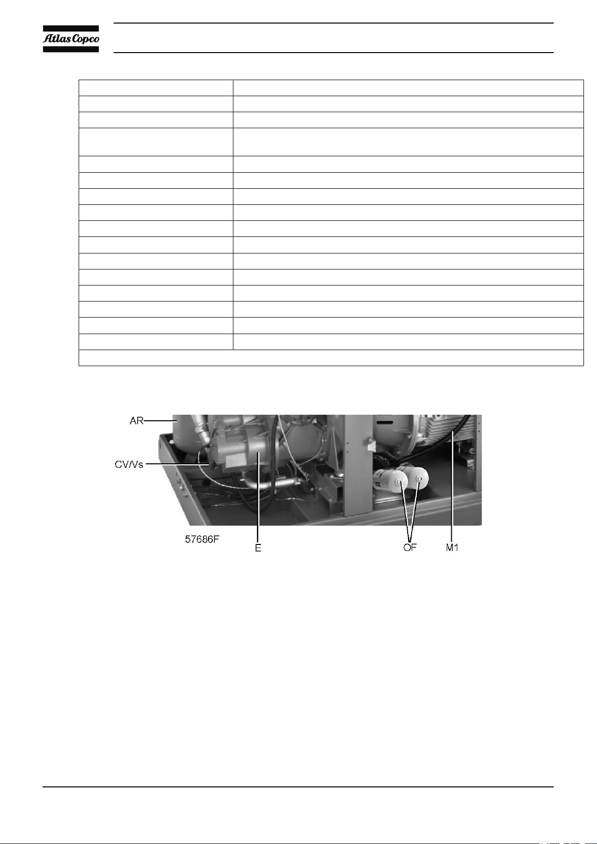
Air flow
Air drawn through filter (AF) is compressed in compressor element (E). Compressed air and oil are discharged
through check valve (CV) to air receiver/oil separator (AR) where oil is separated from the compressed air.
The air is blown through minimum pressure valve (Vp) to air cooler (Ca).
On GA Pack compressors, the cooled air is discharged through condensate trap (MTa) and outlet (AOw)
towards the air net.
Check valve (CV) prevents blow-back of compressed air.
Minimum pressure valve (Vp) prevents the receiver pressure from dropping below a minimum pressure. The
valve has a built-in check valve.
Oil system
Air pressure forces the oil from receiver (AR) through oil cooler (Co), filters (OF), oil stop valve (Vs) and an
oil injection valve to the compressor element (E) and the lubrication points. The oil injection valve will open
at higher ambient temperatures to keep the element outlet temperature low.
A by-pass valve by-passes the oil cooler (Co) when the injection pressure is low, to ensure a sufficient initial
oil flow to the element when starting the compressor or when switching from unload to load.
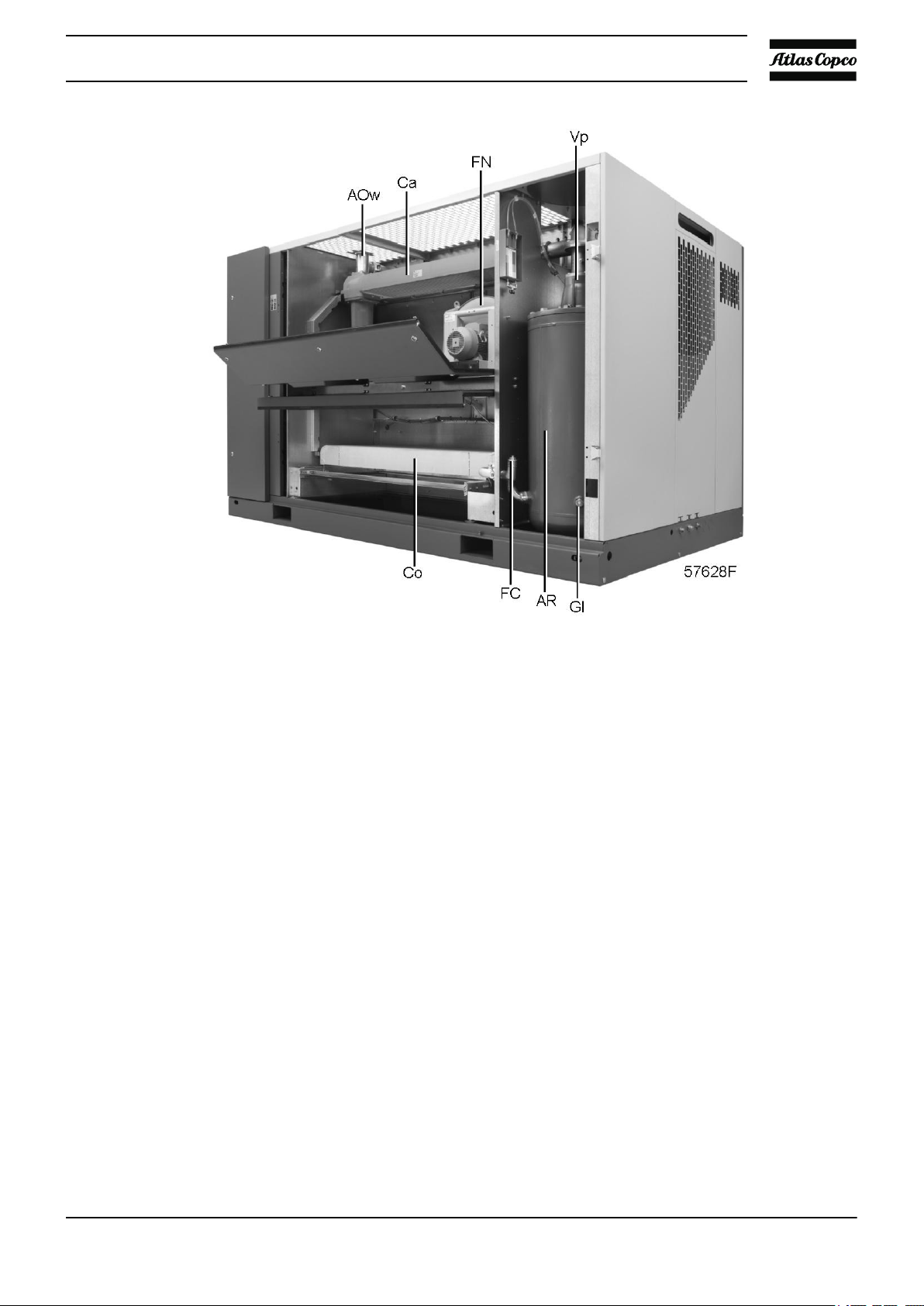
Rear view of air-cooled GA
For air-cooled units, the oil temperature is controlled by regulating the speed of the fans (FN), to avoid
overcooling and consequently condensation in the air receiver (AR).
APF192090 15
In the air receiver (AR) most of the oil is removed from the air centrifugally. Almost all of the remaining oil
is removed by the separator element.
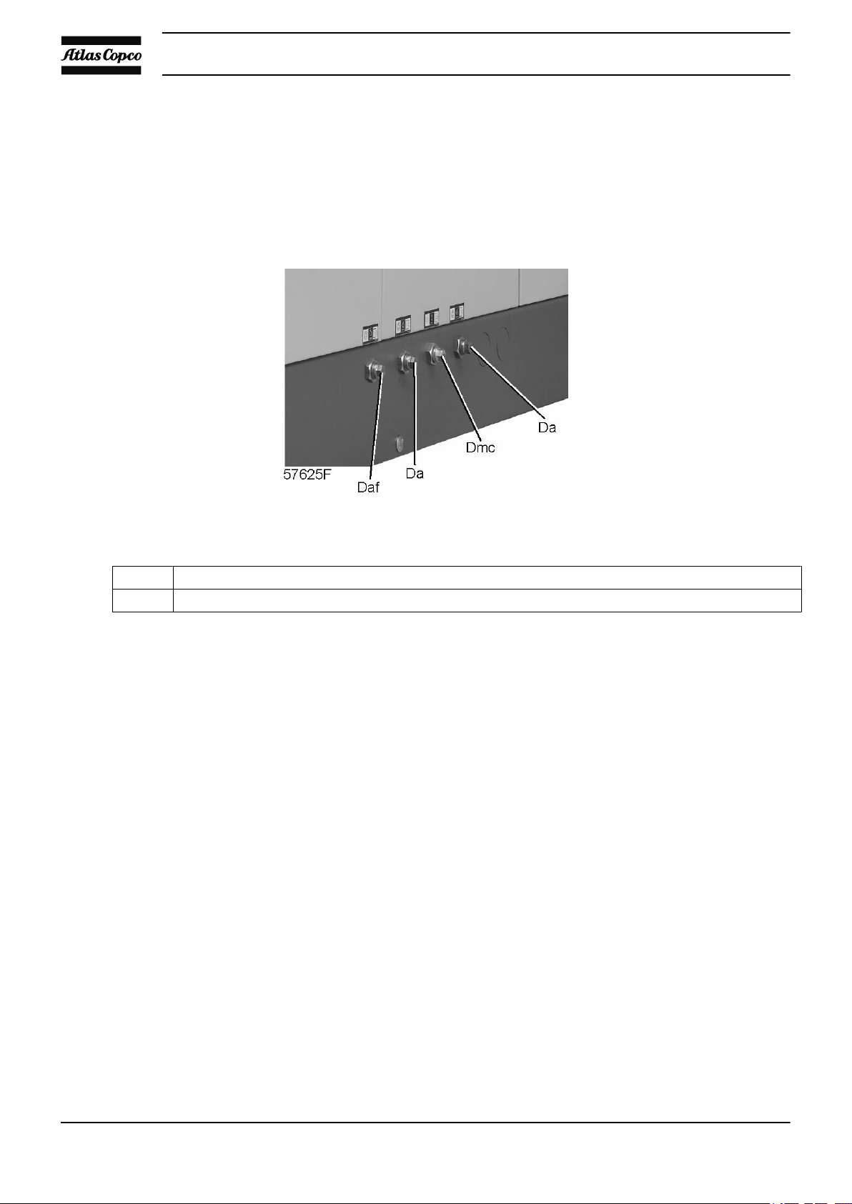
2.3 Cooling and condensate system
Condensate drain system
Instruction book
Dac Automatic condensate drain, compressor
Dmc Manual condensate drain
A condensate trap is installed downstream of the air cooler to prevent condensate from entering the air outlet
pipe. The trap is provided with a float valve for automatically draining condensate and with a manual drain
valve.
Cooling system
On air-cooled compressors, the air and oil coolers are cooled by fans.
Condensate drains of air-cooled GA
16 APF192090
Instruction book
3 Elektronikon regulator
3.1 Elektronikon control system
Main functions
In general, the Elektronikon regulator has the following functions:
• Controlling the motor speed (Variable Speed Drive), reducing the power consumption and pressure band.
• Controlling the speed of the fans of the coolers, reducing the power consumption and noise level.
• Protecting the compressor.
• Monitoring components - service warning.
• Automatic restart after voltage failure.
Controlling the compressor speed - reducing power consumption and pressure band
VSD compressors optimise the power consumption and reduce the operating pressure band by matching the
motor speed to the air net pressure.
The regulator will continuously vary the motor speed maintaining the net pressure as close as possible to the
programmed pressure set-point. The pressure fluctuations will be very low.
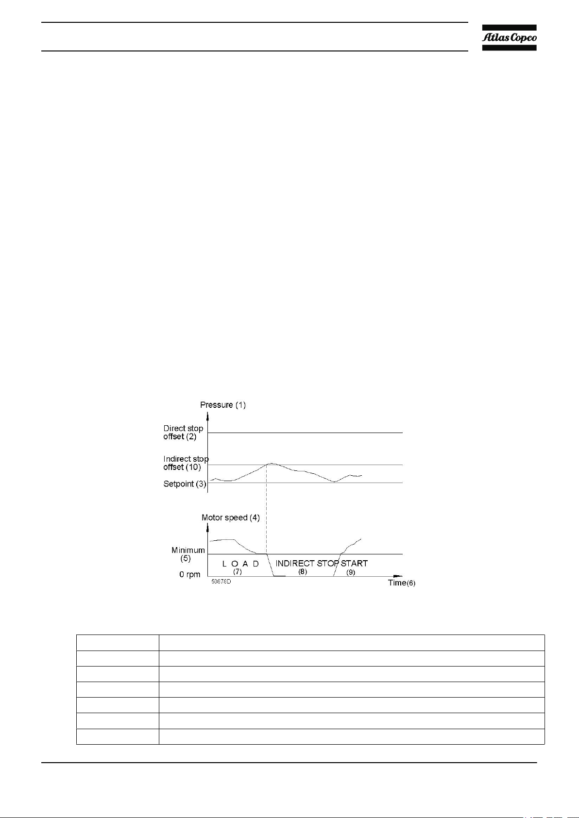
Indirect stopping
Example of a pressure/time diagram
Ref. Designation
(1) Pressure
(2) Direct stop offset
(3) Set-point
(4) Motor speed
(5) Minimum
(6) Time
APF192090 17
Ref. Designation
(7) Load
(8) Indirect stop
(9) Start
(10) Indirect stop offset
If the motor is running at minimum speed and the net pressure rises to a value equal to the sum of the
programmed pressure set-point and the programmed indirect stop offset, the compressor will stop.
When the net pressure drops, the regulator will calculate the optimum moment to restart the compressor to
avoid the net pressure decreasing below the pressure set-point (anticipated starting).
Direct stopping
If the net pressure should rise to a value equal to the sum of the programmed pressure set-point and the
programmed direct stop offset, the compressor will be stopped immediately.
The regulator will calculate the optimum moment to restart the compressor.
Instruction book
Protecting the compressor
Shut-down and motor overload
If the element outlet temperature or compressor outlet temperature exceeds the programmed shut-down level,
the compressor will be stopped. LED (2) will flash and a message will appear on display (1).
The compressor will also be stopped if there is overload of the drive motor.
On air-cooled compressors, the compressor will also stop if there is overload of the fan motors.
Control panel
Consult the section Maintenance warnings and remedy the problem. After remedying the problem and when
the shut-down condition has disappeared, switch on the voltage and press the Reset key.
Shut-down warning
If the element outlet temperature or compressor outlet temperature exceeds a programmed value below the
shut-down level, LED (2) will be lit and a message will appear on display (1) to warn the operator before the
shut-down level is reached.
Consult the section Maintenance warnings, stop the compressor and remedy the problem.
The message disappears as soon as the warning condition disappears.
18 APF192090

Instruction book
Service warning
A number of service operations are grouped (called Level A, B, C, ...). Each level has a programmed time
interval. If a time interval is exceeded, a message will appear on display (1) to warn the operator to carry out
the service actions belonging to that level.
Automatic restart after voltage failure
The regulator has a built-in function to automatically restart the compressor if the voltage is restored after
voltage failure. This function is deactivated in compressors leaving the factory. If desired, the function can
be activated. Consult Atlas Copco.
If activated and provided the module was in the automatic operation mode, the compressor
will automatically restart if the supply voltage to the module is restored within a
programmed time period.
The power recovery time (the period within which the voltage must be restored to have an
automatic restart) can be set between 15 and 3600 seconds or to Infinite. If the power
recovery time is set to Infinite, the compressor will always restart after a voltage failure,
no matter how long it takes to restore the voltage. A restart delay can also be programmed,
allowing e.g. two compressors to be restarted one after the other.
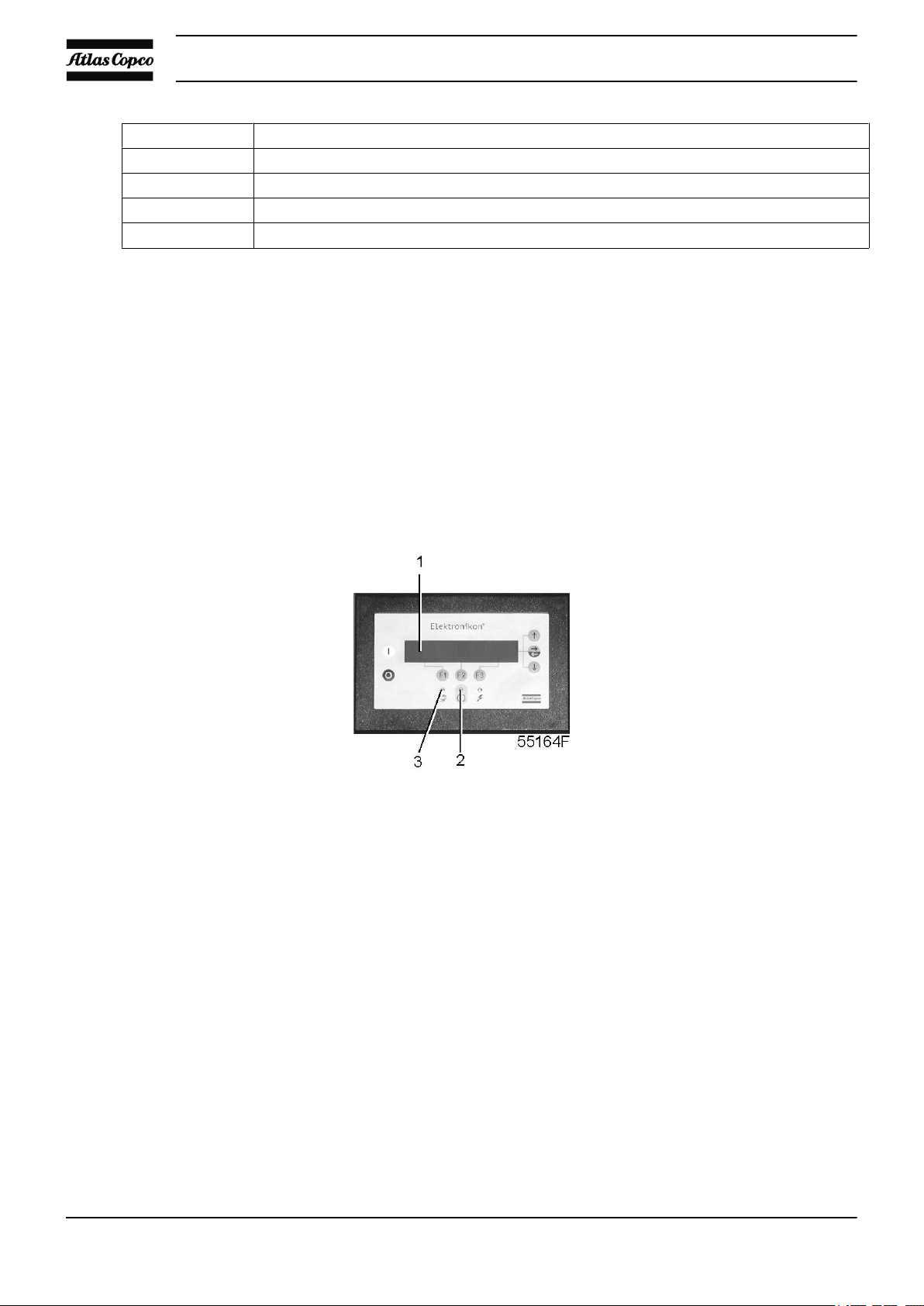
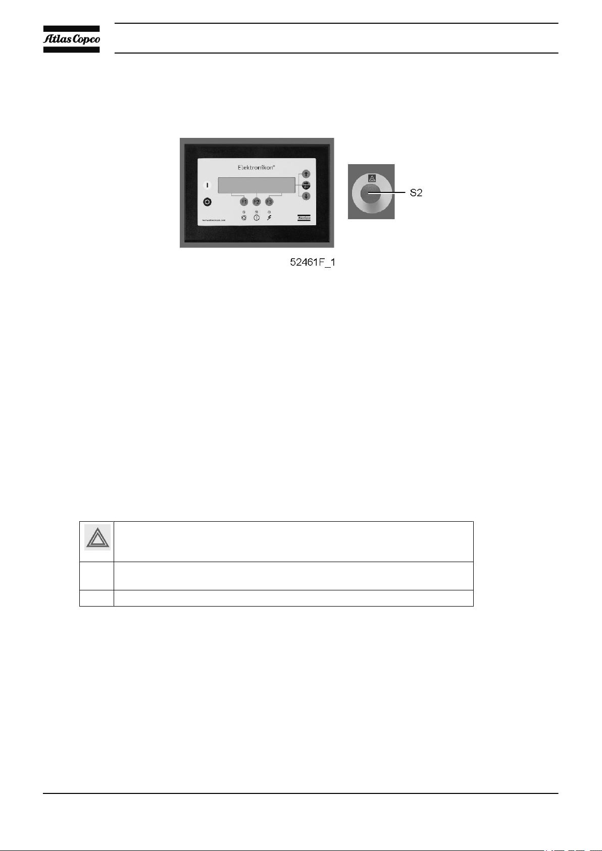
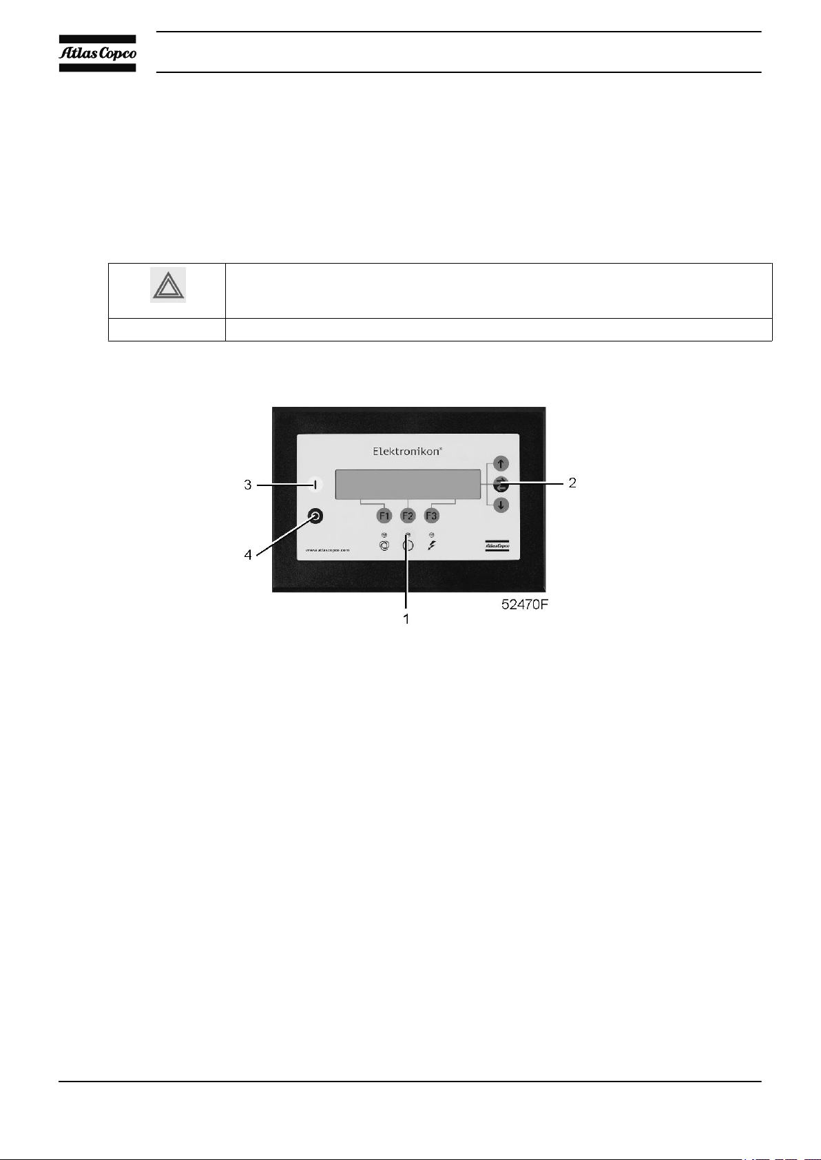
3.2 Control panel
Elektronikon regulator
Parts and functions
Control panel
Reference Designation Function
1 Start button Button to start the compressor. LED (8) lights up
indicating that the Elektronikon regulator is operative.
2 Display Shows messages about the compressor operating
condition, a service need or a fault.
3 Scroll keys Keys to scroll upwards or downwards through the
display.
APF192090 19
Instruction book
Reference Designation Function
4 Tabulator key Key to select the parameter indicated by the horizontal
arrow. Only the parameters followed by an arrow
pointing to the right can be modified.
5 Function keys Keys to control and program the compressor.
6 Voltage on LED Indicates that the voltage is switched on.
7 General alarm LED Is lit if a shut-down warning condition exists or
maintenance is required.
7 General alarm LED Flashes if a shut-down condition exists, if an important
sensor is out of order or after an emergency stop.
8 Automatic operation LED Indicates that the regulator is automatically controlling
the compressor.
9 Stop button Button to stop the compressor. LED (8) goes out.
S2 Emergency stop button Push button to stop the compressor immediately in the
event of an emergency. After remedying the trouble,
unlock the button by pulling it out.
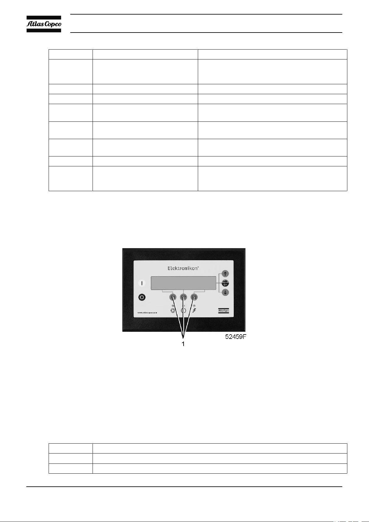
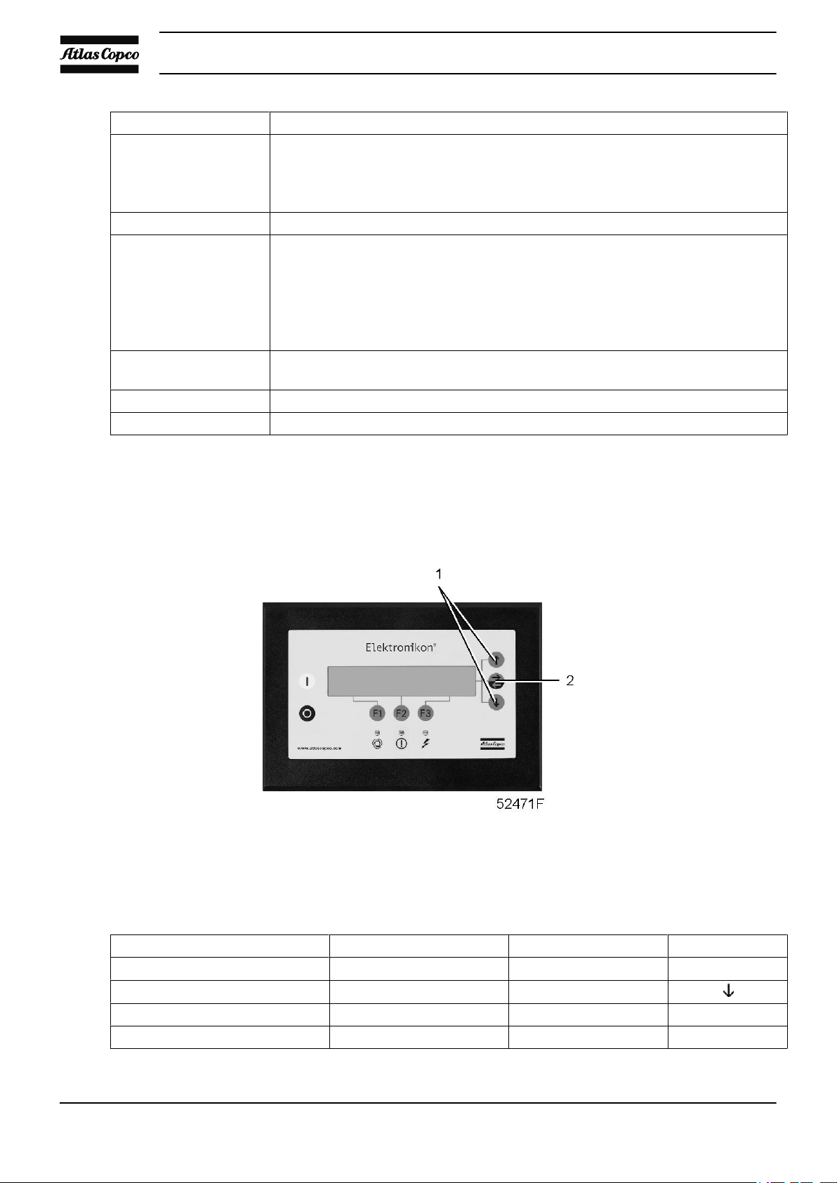
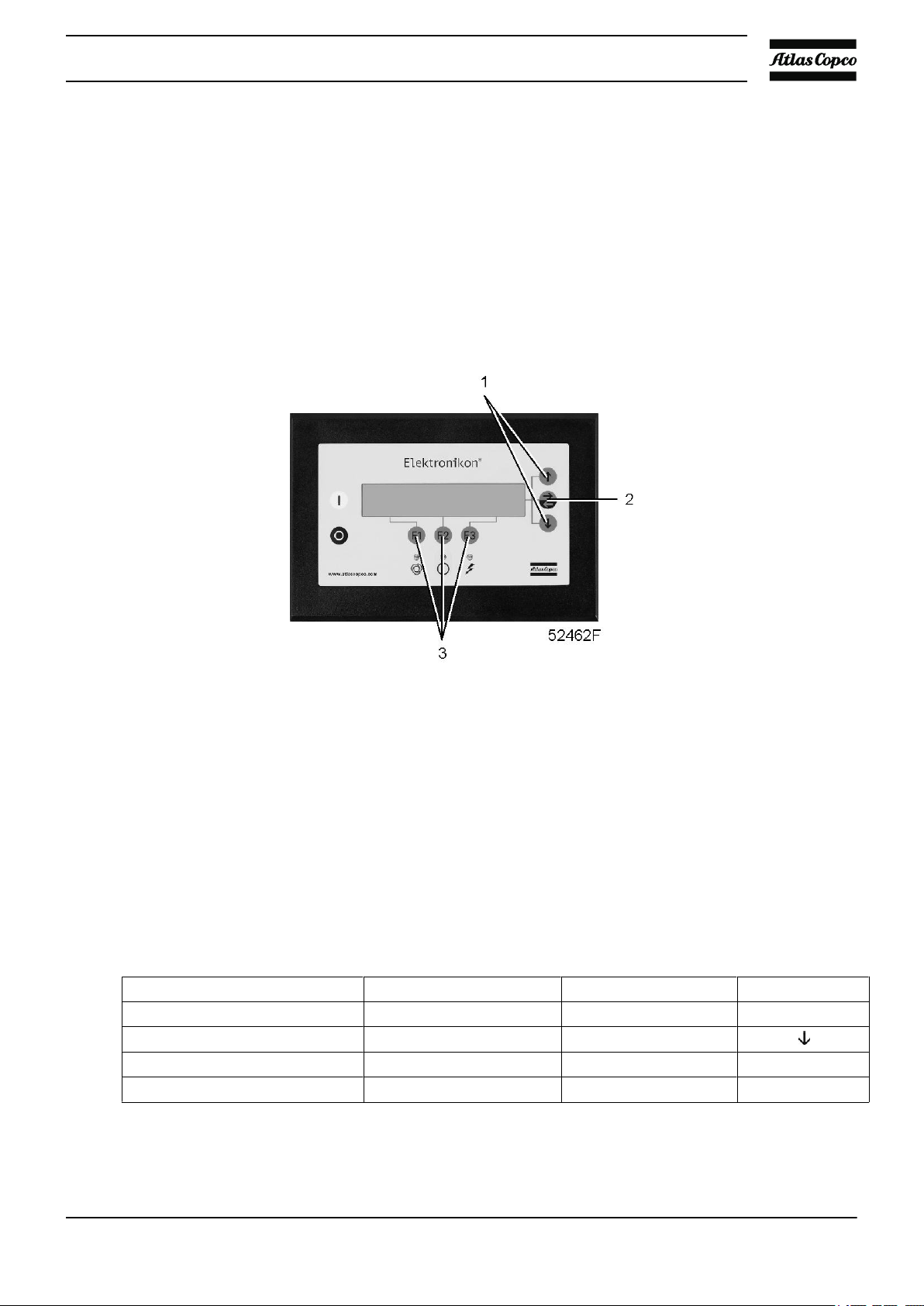
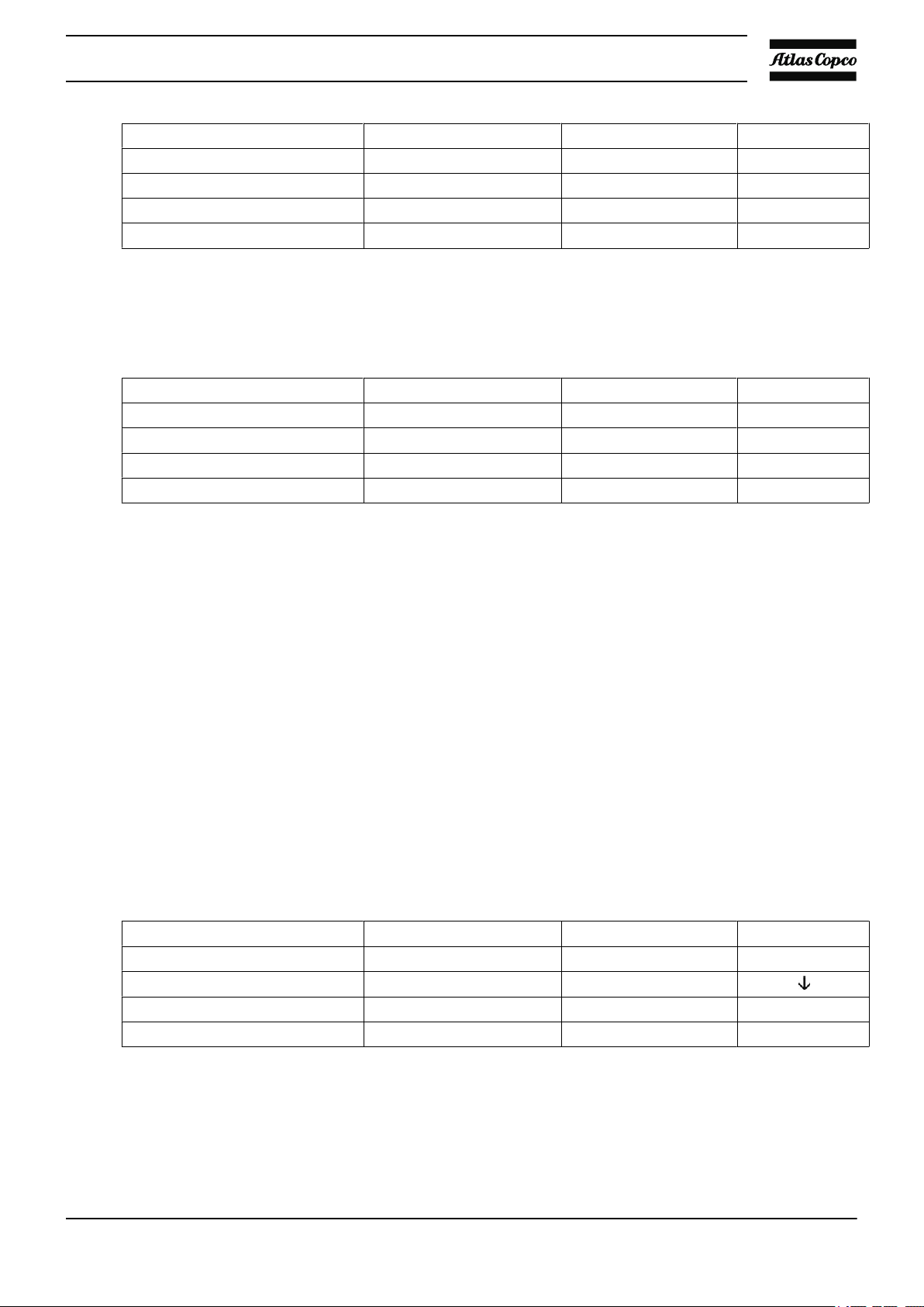
3.3 Function keys
Control panel
Function keys
The keys (1) are used:
• To manually load/unload the compressor (not for VSD compressors)
• To call up or to program settings
• To reset a motor overload, shut-down or service message, or an emergency stop
• To access all data collected by the regulator
The functions of the keys vary depending on the displayed menu. The actual function is indicated just above
the relevant key. The most common functions are listed below:
Designation Function
“Add” To add compressor start/stop commands (day/hour)
“Back” To return to a previously shown option or menu
20 APF192090
Instruction book
Designation Function
“Cancel” To cancel a programmed setting when programming parameters
“Delete” To delete compressor start/stop commands
“Help” To find the Atlas Copco internet address
“Limits” To show limits for a programmable setting
“Load” Not used on VSD (Variable Speed Drive) compressors
“Mainscreen” To return from a menu to the main screen
“Menu” Starting from the main screen, to have access to the submenus
“Menu” Starting from a submenu, to return to a previous menu
“Modify” To modify programmable settings
“Program” To program modified settings
“Reset” To reset a timer or message
“Return” To return to a previously shown option or menu
“Unload” Not used on VSD (Variable Speed Drive) compressors
“Extra” To find the module configuration of the regulator
To load the compressor manually
To unload the compressor manually
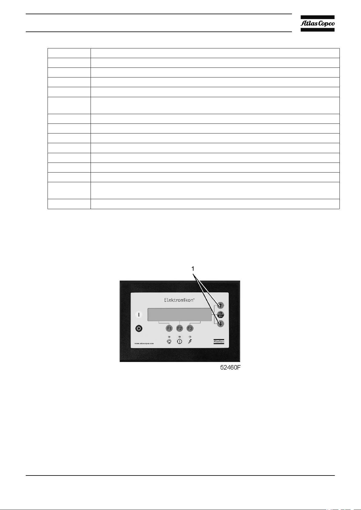
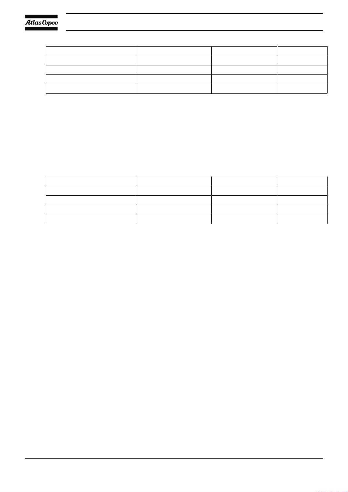
3.4 Scroll keys
Control panel
The keys (1) allow the operator to scroll through the display.
As long as a downwards pointing arrow is shown at the utmost right position of the display, the scroll key
with the same symbol can be used to see the next item.
As long as an upwards pointing arrow is shown at the utmost right position of the display, the scroll key with
the same symbol can be used to see the previous item.
When the scroll key is kept pressed, the scrolling is continued.
APF192090 21
3.5 Emergency stop button
Control panel
Description
In case of emergency, press button (S2) to stop the compressor immediately.
Instruction book
Using the emergency stop breaks the circuit to:
• the variable speed drive unit of the drive motor.
• on air-cooled compressors, the variable speed drive unit of the fan motors.
•
• on GA (W) VSD Full-Feature compressors, the variable speed drive unit of the compressor motor of the
dryer.
By using the emergency stop, solenoid valve (Y2) will open the blow-off port, resulting in depressurisation
of the air receiver.
At the occurrence of an emergency stop, the compressor element is stopped immediately and the solenoid
valve will be deactivated by Elektronikon ® regulator. No unload status is reached. The check valve prevents
oil flow back from reversed rotation of the compressor element.
Before starting any maintenance or repairs, wait until the compressor has
stopped and open the isolating switch (customer's installation) to switch off the
voltage to the compressor.
Close the air outlet valve and open the manual condensate drain valves to
depressurize the air system.
Apply all relevant Safety precautions.
3.6 Control programs
Function
In order to facilitate programming and controlling, menu-driven control programs have been implemented in
the regulator.
22 APF192090
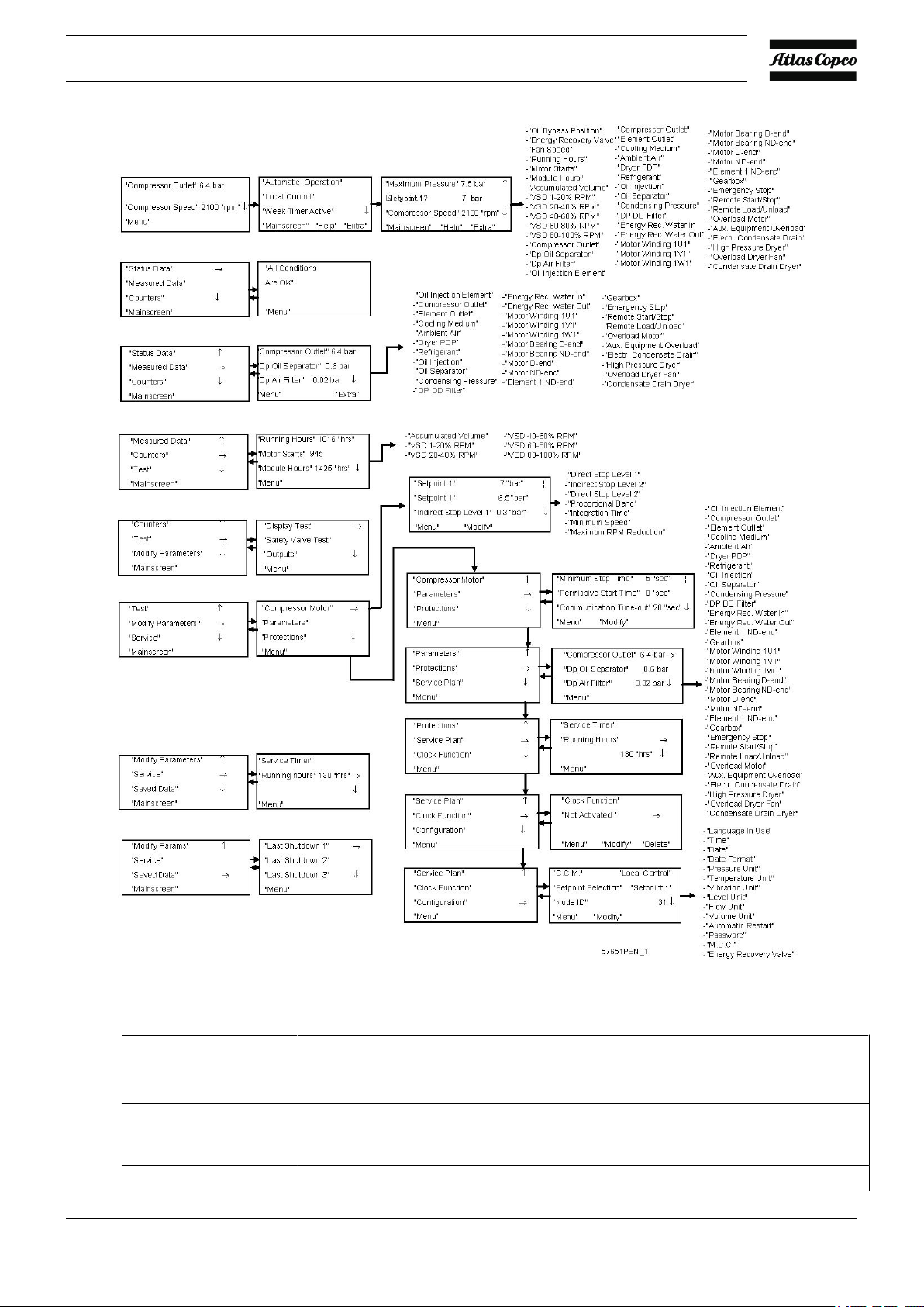
Instruction book
Menu flow for air-cooled GA 132/160 VSD compressors (simplified example)
Program Function
Main screen Shows in brief the operational status of the compressor. Is the gateway to all
functions.
“Status Data” Calls up the status of the compressor protection functions (shut-down, shut-down
warning and service warning). Resets a shut-down, motor overload and service
condition.
“Measured Data” Calls up the data currently measured and the status of a number of inputs.
APF192090 23
Instruction book
Program Function
“Counters” Calls up:
running hours
•
regulator (module) hours
•
number of motor starts
•
“Test” Display test.
“Modify Parameters” Modifying the settings for:
Parameters (e.g. loading and unloading pressures)
•
Protections (e.g. temperature shut-down level)
•
Service plans (timers for service plans)
•
Clock functions (automatic compressor start/stop/pressure band commands)
•
Configuration (time, date, display language,...)
•
“Service” Calls up service plans and resets the timers after carrying out the service actions in
a service plan.
“Saved Data" Calls up the saved data: last shut-down, last emergency stop data.
“Unload”/”Load” Loads and unloads the compressor manually.
3.7 Calling up menus
Description
When the voltage is switched on, the Main screen is shown automatically.
Control panel
Example of Main screen of GA 132/160 VSD compressors
“Compressor Outlet” 7.5 bar
.
“Compressor Speed” 2100 rpm
“Menu”
F1 F2 F3
24 APF192090
Instruction book
After pressing the “Menu” (F1) key, the option “Status Data” will be followed by a horizontal arrow:
• Either press the tabulator key (2) to select this menu,
• or use the arrow down key (1) until the desired submenu is followed by a horizontal arrow and then press
the tabulator key (2) to select this menu.
The arrow down key (1) can be used for a quick look at the actual compressor status.
3.8 Main screen menu
Function
The Main screen menu shows the status of the compressor operation and is the gateway to all functions
implemented in the regulator.
Procedure
The Main screen is shown automatically when the voltage is switched on.
If the function or arrow keys (1, 2 and 3) are not used for some minutes, the regulator will automatically return
to the Main screen.
Whenever displayed on a submenu screen, press the “Mainscreen” (F1) key to return to the Main screen.
Example of Main screen of GA 132/160 VSD compressors
“Compressor Outlet” 7.5 bar
.
“Compressor Speed” 2100 rpm
“Menu”
F1 F2 F3
Control panel
The display indicates:
• The name of the sensor and its actual reading
APF192090 25
• Messages regarding the compressor operating condition
• Just above the function keys (3), the actual functions of these keys
3.9 Status data menu
Warning
Before starting any maintenance or repairs, press the stop button (4), wait until the
compressor has stopped, press the red emergency stop button and open the isolating
switch (customer's installation) to switch off the voltage to the compressor.
Close the air outlet valve and depressurize the air system.
Function
Instruction book
The Status data submenu gives information regarding the status of the compressor protection functions (shutdown, shut-down warning and service warning) and allows resetting of a shut-down, motor overload and
service condition.
Procedure
Starting from the Main screen (see Main screen menu):
• Press the key “Menu” (F1): the option “Status Data” will be followed by a horizontal arrow.
• Press the tabulator key (2).
No message exists
• General alarm LED (1) is out and the message on the display will indicate that all conditions are normal:
Control panel
26 APF192090
Instruction book
“All Conditions Are OK”
.
.
“Menu” “Help”
F1 F2 F3
A shut-down message exists
• In case the compressor is shut down, LED (1) will blink.
• In case of a shut-down due to too high a temperature at the outlet of the compressor element:
“Element Outlet” 114˚C
.
“Shutdown” “Maximum” 110˚C
“Menu”*** “Help” ***”Reset”
F1 F2 F3
• The indicators (***) are blinking. The screen shows the actual reading and the shut-down setting.
• It remains possible to scroll through other menus, e.g. to check the values of other parameters.
When returning to the “Status Data” menu, the option “Shutdowns” will blink. This option can be selected
by pressing the tabulator key (2) to return to the above shut-down screen.
Shut-down reset
• Switch off the voltage and remedy the trouble. After remedying and when the shut-down condition has
disappeared, switch on the voltage and press the key “Reset” (F3).
• Press the keys “Menu” and “Mainscreen” to return to the Main screen and restart the compressor by means
of start button (3).
A shut-down warning message exists
A shut-down warning level is a programmable level below the shut-down level.
• If a shut-down warning exists, LED (1) is alight. The Main screen will change into a screen similar to the
one below:
“Compressor Outlet” 7.0 bar
.
*** “Shutdown Warning” ***
“Menu”*** ***
F1 F2 F3
• The message “Shutdown Warning” appears.
• Press the key “Menu” (F1) and the tabulator key (2) to select the “Status data” menu; the option
“Protection” is blinking.
• Scroll to this option and select it by pressing the tabulator key (2). A screen similar to the one below
appears:
APF192090 27
“Element 1 Outlet” 103˚C
.
“Shutd. Warn.” “Maximum” 100˚C
“Menu”*** ***
F1 F2 F3
• The screen indicates that the temperature at the outlet of compressor element 1 exceeds the programmed
shut-down warning level.
• If necessary, stop the compressor by means of stop button (4) and wait until it has stopped.
• Switch off the voltage, inspect and remedy.
• The warning message will disappear automatically as soon as the warning condition disappears.
A service warning exists
• LED (1) is alight. The Main screen will change into a screen similar to the one below:
“Compressor Outlet” 7.0 bar
.
“*Service Required*”
“Menu”*** ***
F1 F2 F3
Instruction book
• The indicators (***) are blinking and the service warning message appears.
• Press the key Menu (F1) and the tabulator key (2) to select the “Status data” menu: the option “Service”
is blinking.
• Scroll to this option and select it by pressing the tabulator key (2); two options may blink:
• “Inputs”: if the programmed service level of a component is exceeded (e.g. the maximum pressure
drop of the air filter).
• “Plan”: if a service plan interval is exceeded.
• Stop the compressor and switch off the voltage.
• In case the service message was referring to “Inputs” (air filter): replace the filter, switch on the voltage,
scroll in the “Status Data” menu to “Inputs” and press the “Reset” key to reset the service message.
• In case the service message was referring to “Plan”: carry out the service actions related to the indicated
plans. Reset the timers of the related plans. Contact your Atlas Copco Customer Centre. See Service menu.
28 APF192090
 Loading...