

Atlas Copco GA 5 VSD MED, GA 7 VSD MED, GA 11 VSD MED, GA 15 VSD MED, GA 15 MED Instruction Book
...
Atlas Copco
Oil-injected rotary screw compressors
GA 5 VSD MED, GA 7 VSD MED, GA 11 VSD MED, GA 15 VSD MED
Medical
Instruction book


Atlas Copco
Oil-injected rotary screw compressors
GA 5 VSD MED, GA 7 VSD MED, GA 11 VSD MED, GA 15
VSD MED
Medical
From following serial No. onwards: CAI 708 272
Instruction book
Original instructions
2011 - 11
Copyright notice
Any unauthorized use or copying of the contents or any part thereof is prohibited.
This applies in particular to trademarks, model denominations, part numbers and drawings.
This instruction book is valid for CE as well as non-CE labelled machines. It meets the
requirements for instructions specified by the applicable European directives as identified
in the Declaration of Conformity.
No. 2920 7104 10
www.atlascopco.com

Instruction book
Table of contents
1 Safety precautions..........................................................................................................5
1.1 SAFETY ICONS...................................................................................................................................5
1.2 SAFETY PRECAUTIONS, GENERAL...........................................................................................................5
1.3 SAFETY PRECAUTIONS DURING INSTALLATION...........................................................................................6
1.4 SAFETY PRECAUTIONS DURING OPERATION..............................................................................................7
1.5 SAFETY PRECAUTIONS DURING MAINTENANCE OR REPAIR...........................................................................8
2 General description......................................................................................................10
2.1 INTRODUCTION.................................................................................................................................10
2.2 AIR FLOW.......................................................................................................................................11
2.3 OIL FLOW.......................................................................................................................................12
2.4 COOLING SYSTEM.............................................................................................................................13
2.5 CONDENSATE SYSTEM.......................................................................................................................14
2.6 REGULATING SYSTEM........................................................................................................................14
2.7 ELECTRICAL SYSTEM.........................................................................................................................15
2.8 ELECTRICAL DIAGRAM........................................................................................................................16
2.9 AIR RECEIVER..................................................................................................................................18
3 Elektronikon® Graphic controller...............................................................................19
3.1 GENERAL........................................................................................................................................19
3.2 CONTROL PANEL..............................................................................................................................21
3.3 ICONS USED....................................................................................................................................22
3.4 MAIN SCREEN..................................................................................................................................26
3.5 CALLING UP MENUS..........................................................................................................................30
3.6 INPUTS MENU...................................................................................................................................32
3.7 OUTPUTS MENU...............................................................................................................................35
3.8 COUNTERS......................................................................................................................................36
3.9 LAN OR LOCAL CONTROL..................................................................................................................38
2 2920 7104 10

Instruction book
3.10 EMERGENCY FORCED LOCAL...............................................................................................................38
3.11 SERVICE MENU................................................................................................................................39
3.12 MODIFYING THE SETPOINT..................................................................................................................43
3.13 EVENT HISTORY MENU.......................................................................................................................45
3.14 MODIFYING GENERAL SETTINGS...........................................................................................................46
3.15 INFO MENU......................................................................................................................................48
3.16 TEST MENU.....................................................................................................................................49
3.17 USER PASSWORD MENU.....................................................................................................................50
3.18 WEB SERVER..................................................................................................................................51
3.19 CASCADING LOAD CUT-IN VALUES IN LOCAL MODE...................................................................................58
3.20 PROGRAMMABLE SETTINGS.................................................................................................................59
4 Installation.....................................................................................................................61
4.1 DIMENSION DRAWINGS.......................................................................................................................61
4.2 INSTALLATION PROPOSAL...................................................................................................................62
4.3 ELECTRICAL CONNECTIONS.................................................................................................................64
4.4 PICTOGRAPHS.................................................................................................................................65
5 Operating instructions.................................................................................................66
5.1 INITIAL START-UP..............................................................................................................................66
5.2 STARTING ......................................................................................................................................68
5.3 DURING OPERATION..........................................................................................................................69
5.4 CHECKING THE DISPLAY.....................................................................................................................71
5.5 STOPPING ......................................................................................................................................72
5.6 TAKING OUT OF OPERATION................................................................................................................72
6 Maintenance..................................................................................................................74
6.1 PREVENTIVE MAINTENANCE SCHEDULE..................................................................................................74
6.2 OIL SPECIFICATIONS..........................................................................................................................76
6.3 STORAGE AFTER INSTALLATION...........................................................................................................77
2920 7104 10 3

Instruction book
6.4 SERVICE KITS..................................................................................................................................77
6.5 DISPOSAL OF USED MATERIAL.............................................................................................................77
7 Adjustments and servicing procedures.....................................................................78
7.1 DRIVE MOTOR .................................................................................................................................78
7.2 AIR FILTER......................................................................................................................................78
7.3 OIL AND OIL FILTER CHANGE...............................................................................................................79
7.4 OIL SEPARATOR CHANGE...................................................................................................................80
7.5 COOLERS.......................................................................................................................................81
7.6 BELT TENSIONING AND REPLACEMENT...................................................................................................81
7.7 SAFETY VALVES...............................................................................................................................83
8 Problem solving............................................................................................................85
9 Technical data...............................................................................................................88
9.1 READINGS ON DISPLAY......................................................................................................................88
9.2 ELECTRIC CABLE SIZE AND MAIN FUSES................................................................................................88
9.3 REFERENCE CONDITIONS AND LIMITATIONS............................................................................................91
9.4 COMPRESSOR DATA..........................................................................................................................92
9.5 TECHNICAL DATA ELEKTRONIKON® CONTROLLER....................................................................................94
10 Instructions for use......................................................................................................96
11 Guidelines for inspection.............................................................................................97
12 Pressure equipment directives...................................................................................98
13 Declaration of conformity............................................................................................99
4 2920 7104 10
Instruction book
1 Safety precautions
1.1 Safety icons
Explanation
Danger for life
Warning
Important note
1.2 Safety precautions, general
General precautions
1. The operator must employ safe working practices and observe all related work safety requirements and
regulations.
2. If any of the following statements does not comply with the applicable legislation, the stricter of the two
shall apply.
3. Installation, operation, maintenance and repair work must only be performed by authorized, trained,
specialized personnel.
4. The compressor is not considered capable of producing air of breathing quality. For air of breathing quality,
the compressed air must be adequately purified according to the applicable legislation and standards.
5. Before any maintenance, repair work, adjustment or any other non-routine checks, stop the compressor,
press the emergency stop button, switch off the voltage and depressurize the compressor. In addition, the
power isolating switch must be opened and locked.
On units powered by a frequency converter, wait six minutes before starting any electrical repair.
If the machine is equipped with an automatic restart after voltage failure function and if this
function is active, be aware that the machine will restart automatically when the power is
restored if it was running when the power was interrupted!
6. Never play with compressed air. Do not apply the air to your skin or direct an air stream at people. Never
use the air to clean dirt from your clothes. When using the air to clean equipment, do so with extreme
caution and wear eye protection.
7. The owner is responsible for maintaining the unit in safe operating condition. Parts and accessories shall
be replaced if unsuitable for safe operation.
8. It is not allowed to walk or stand on the roof of the unit.
2920 7104 10 5

1.3 Safety precautions during installation
All responsibility for any damage or injury resulting from neglecting these precautions, or
non observance of the normal caution and care required for installation, operation,
maintenance and repair, even if not expressly stated, will be disclaimed by the
manufacturer.
Precautions during installation
1. The machine must only be lifted using suitable equipment in accordance with the applicable safety
regulations. Loose or pivoting parts must be securely fastened before lifting. It is strictly forbidden to
dwell or stay in the risk zone under a lifted load. Lifting acceleration and deceleration must be kept within
safe limits. Wear a safety helmet when working in the area of overhead or lifting equipment.
2. The unit is designed for indoor use. If the unit is installed outdoors, special precautions must be taken;
consult your supplier.
3. Place the machine where the ambient air is as cool and clean as possible. If necessary, install a suction
duct. Never obstruct the air inlet. Care must be taken to minimize the entry of moisture at the inlet air.
4. Any blanking flanges, plugs, caps and desiccant bags must be removed before connecting the pipes.
5. Air hoses must be of correct size and suitable for the working pressure. Never use frayed, damaged or
worn hoses. Distribution pipes and connections must be of the correct size and suitable for the working
pressure.
6. The aspirated air must be free of flammable fumes, vapours and particles, e.g. paint solvents, that can lead
to internal fire or explosion.
7. Arrange the air intake so that loose clothing worn by people cannot be sucked in.
8. Ensure that the discharge pipe from the compressor to the aftercooler or air net is free to expand under
heat and that it is not in contact with or close to flammable materials.
9. No external force may be exerted on the air outlet valve; the connected pipe must be free of strain.
10. If remote control is installed, the machine must bear a clear sign stating: DANGER: This machine is
remotely controlled and may start without warning.
The operator has to make sure that the machine is stopped and that the isolating switch is open and locked
before any maintenance or repair. As a further safeguard, persons switching on remotely controlled
machines shall take adequate precautions to ensure that there is no one checking or working on the
machine. To this end, a suitable notice shall be affixed to the start equipment.
11. Air-cooled machines must be installed in such a way that an adequate flow of cooling air is available and
that the exhausted air does not recirculate to the compressor air inlet or cooling air inlet.
12. The electrical connections must correspond to the applicable codes. The machines must be earthed and
protected against short circuits by fuses in all phases. A lockable power isolating switch must be installed
near the compressor.
13. On machines with automatic start/stop system or if the automatic restart function after voltage failure is
activated, a sign stating "This machine may start without warning" must be affixed near the instrument
panel.
14. In multiple compressor systems, manual valves must be installed to isolate each compressor. Non-return
valves (check valves) must not be relied upon for isolating pressure systems.
15. Never remove or tamper with the safety devices, guards or insulation fitted on the machine. Every pressure
vessel or auxiliary installed outside the machine to contain air above atmospheric pressure must be
protected by a pressure relieving device or devices as required.
16. Piping or other parts with a temperature in excess of 80˚C (176˚F) and which may be accidentally touched
by personnel in normal operation must be guarded or insulated. Other high temperature piping must be
clearly marked.
17. For water-cooled machines, the cooling water system installed outside the machine has to be protected by
a safety device with set pressure according to the maximum cooling water inlet pressure.
Instruction book
6 2920 7104 10
Instruction book
18. If the ground is not level or can be subject to variable inclination, consult the manufacturer.
Also consult following safety precautions: Safety precautions during operation and Safety
precautions during maintenance.
These precautions apply to machinery processing or consuming air or inert gas.
Processing of any other gas requires additional safety precautions typical to the application
which are not included herein.
Some precautions are general and cover several machine types and equipment; hence
some statements may not apply to your machine.
1.4 Safety precautions during operation
All responsibility for any damage or injury resulting from neglecting these precautions, or
non observance of the normal caution and care required for installation, operation,
maintenance and repair, even if not expressly stated, will be disclaimed by the
manufacturer.
Precautions during operation
1. Never touch any piping or components of the compressor during operation.
2. Use only the correct type and size of hose end fittings and connections. When blowing through a hose or
air line, ensure that the open end is held securely. A free end will whip and may cause injury. Make sure
that a hose is fully depressurized before disconnecting it.
3. Persons switching on remotely controlled machines shall take adequate precautions to ensure that there
is no one checking or working on the machine. To this end, a suitable notice shall be affixed to the remote
start equipment.
4. Never operate the machine when there is a possibility of taking in flammable or toxic fumes, vapors or
particles.
5. Never operate the machine below or in excess of its limit ratings.
6. Keep all bodywork doors shut during operation. The doors may be opened for short periods only, e.g. to
carry out routine checks. Wear ear protectors when opening a door.
On compressors without bodywork, wear ear protection in the vicinity of the machine.
7. People staying in environments or rooms where the sound pressure level reaches or exceeds 80 dB(A)
shall wear ear protectors.
8. Periodically check that:
• All guards are in place and securely fastened
• All hoses and/or pipes inside the machine are in good condition, secure and not rubbing
• There are no leaks
• All fasteners are tight
• All electrical leads are secure and in good order
• Safety valves and other pressure relief devices are not obstructed by dirt or paint
• Air outlet valve and air net, i.e. pipes, couplings, manifolds, valves, hoses, etc. are in good repair, free
of wear or abuse
9. If warm cooling air from compressors is used in air heating systems, e.g. to warm up a workroom, take
precautions against air pollution and possible contamination of the breathing air.
10. Do not remove any of, or tamper with, the sound-damping material.
11. Never remove or tamper with the safety devices, guards or insulations fitted on the machine. Every pressure
vessel or auxiliary installed outside the machine to contain air above atmospheric pressure shall be
protected by a pressure relieving device or devices as required.
2920 7104 10 7
Also consult following safety precautions: Safety precautions during installation and Safety
precautions during maintenance.
These precautions apply to machinery processing or consuming air or inert gas.
Processing of any other gas requires additional safety precautions typical to the application
which are not included herein.
Some precautions are general and cover several machine types and equipment; hence
some statements may not apply to your machine.
1.5 Safety precautions during maintenance or repair
All responsibility for any damage or injury resulting from neglecting these precautions, or
non observance of the normal caution and care required for installation, operation,
maintenance and repair, even if not expressly stated, will be disclaimed by the
manufacturer.
Precautions during maintenance or repair
Instruction book
1. Always use the correct safety equipment (such as safety glasses, gloves, safety shoes, etc.).
2. Use only the correct tools for maintenance and repair work.
3. Use only genuine spare parts.
4. All maintenance work shall only be undertaken when the machine has cooled down.
5. A warning sign bearing a legend such as "Work in progress; do not start" shall be attached to the starting
equipment.
6. Persons switching on remotely controlled machines shall take adequate precautions to ensure that there
is no one checking or working on the machine. To this end, a suitable notice shall be affixed to the remote
start equipment.
7. Close the compressor air outlet valve before connecting or disconnecting a pipe.
8. Before removing any pressurized component, effectively isolate the machine from all sources of pressure
and relieve the entire system of pressure.
9. Never use flammable solvents or carbon tetrachloride for cleaning parts. Take safety precautions against
toxic vapours of cleaning liquids.
10. Scrupulously observe cleanliness during maintenance and repair. Keep dirt away by covering the parts
and exposed openings with a clean cloth, paper or tape.
11. Never weld or perform any operation involving heat near the oil system. Oil tanks must be completely
purged, e.g. by steam cleaning, before carrying out such operations. Never weld on, or in any way modify,
pressure vessels.
12. Whenever there is an indication or any suspicion that an internal part of a machine is overheated, the
machine shall be stopped but no inspection covers shall be opened before sufficient cooling time has
elapsed; this to avoid the risk of spontaneous ignition of the oil vapour when air is admitted.
13. Never use a light source with open flame for inspecting the interior of a machine, pressure vessel, etc.
14. Make sure that no tools, loose parts or rags are left in or on the machine.
15. All regulating and safety devices shall be maintained with due care to ensure that they function properly.
They may not be put out of action.
16. Before clearing the machine for use after maintenance or overhaul, check that operating pressures,
temperatures and time settings are correct. Check that all control and shut-down devices are fitted and that
they function correctly. If removed, check that the coupling guard of the compressor drive shaft has been
reinstalled.
17. Every time the separator element is renewed, examine the discharge pipe and the inside of the oil separator
vessel for carbon deposits; if excessive, the deposits should be removed.
8 2920 7104 10
Instruction book
18. Protect the motor, air filter, electrical and regulating components, etc. to prevent moisture from entering
them, e.g. when steam cleaning.
19. Make sure that all sound-damping material and vibration dampers, e.g. damping material on the bodywork
and in the air inlet and outlet systems of the compressor, is in good condition. If damaged, replace it by
genuine material from the manufacturer to prevent the sound pressure level from increasing.
20. Never use caustic solvents which can damage materials of the air net, e.g. polycarbonate bowls.
21. The following safety precautions are stressed when handling refrigerant:
• Never inhale refrigerant vapours. Check that the working area is adequately ventilated; if required, use
• Always wear special gloves. In case of refrigerant contact with the skin, rinse the skin with water. If
breathing protection.
liquid refrigerant contacts the skin through clothing, never tear off or remove the latter; flush
abundantly with fresh water over the clothing until all refrigerant is flushed away; then seek medical
first aid.
Also consult following safety precautions: Safety precautions during installation and Safety
precautions during operation.
These precautions apply to machinery processing or consuming air or inert gas.
Processing of any other gas requires additional safety precautions typical to the application
which are not included herein.
Some precautions are general and cover several machine types and equipment; hence
some statements may not apply to your machine.
2920 7104 10 9
2 General description
2.1 Introduction
GA 5 VSD MED up to GA 15 VSD MED are single-stage, oil-injected screw compressors driven by an electric
motor. The compressors are air-cooled.
The motor is powered by a frequency converter, allowing to adapt the speed to the air demand for optimal
power consumption.
The compressors are controlled by an Elektronikon® Graphic controller.
Instruction book
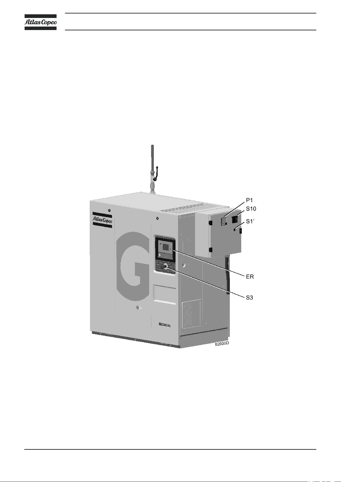
Front view of the compressor
10 2920 7104 10

Instruction book
Reference Name Function
ER Elektronikon® controller See sections Elektronikon Graphic controller -
S3 Emergency stop button To stop the unit in case of emergency
S10 Mains switch To switch off the power to the compressor.
P1 Ammeter Indicates the compressor current.
S1' Hand / Auto (Local / LAN) switch In the Auto (LAN) position, the pump will be
2.2 Air flow
Flow diagram
General and further.
controlled by the ES MED. In Hand (Local) position,
the compressor will be controlled by the settings
programmed in its own controller, bypassing the
control from the ES MED.
LED's indicate the active running mode.
Reference Description
A Intake air
B Air/oil mixture
C Oil
D Wet compressed air
E Condensate
2920 7104 10 11
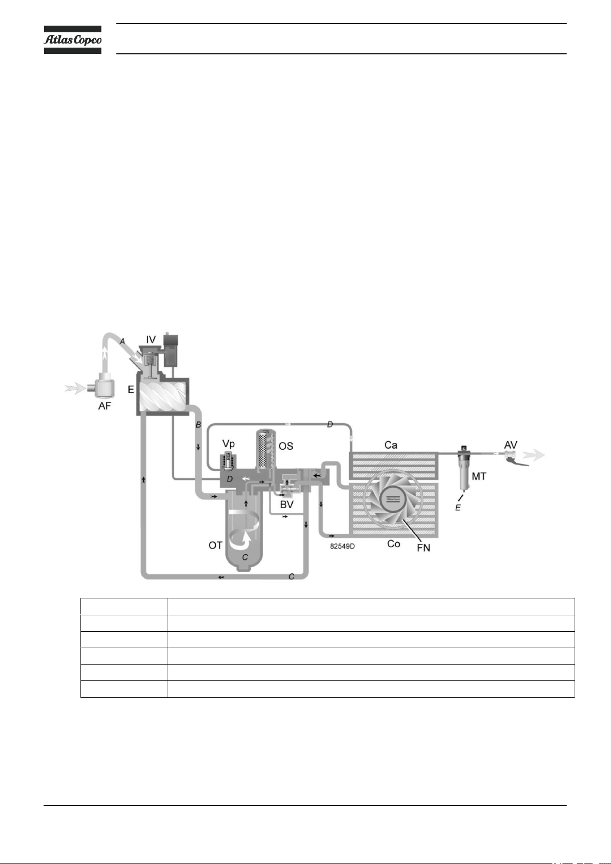
Description
Air drawn through filter (AF) and open inlet valve (IV) into compressor element (E) is compressed.
Compressed air and oil flow into the oil tank (OT). The air is discharged through outlet valve (AV) via
minimum pressure valve (Vp) and air cooler (Ca).
During loaded operation, minimum pressure valve (Vp) keeps the pressure in the separator tank (OT) above
a minimum value, required for lubrication. An integrated check valve prevents the compressed air downstream
the valve from being vented to atmosphere during unloaded operation.
When the compressor is stopped, inlet valve (IV) closes, preventing compressed air and oil to be vented into
the air filter.
A condensate trap (MT) downstream the air cooler is included.
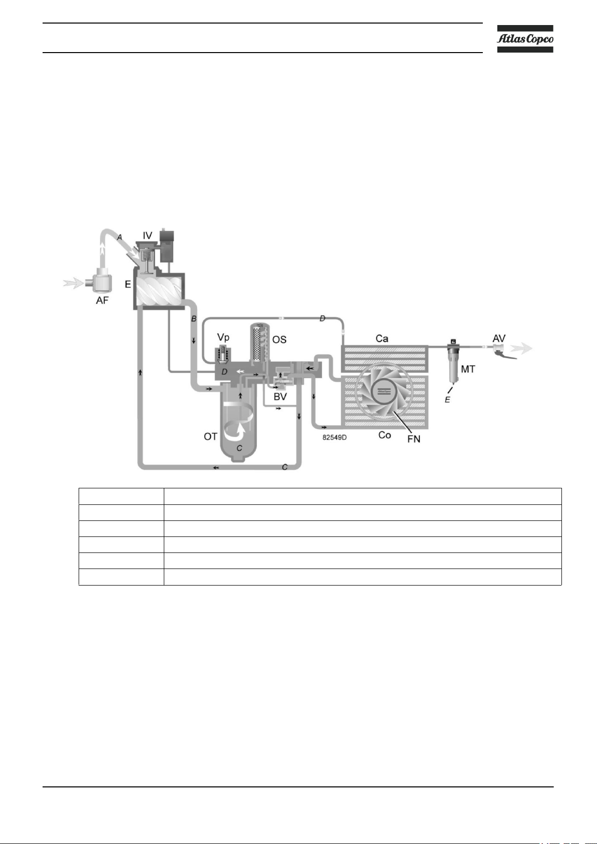
2.3 Oil flow
Flow diagram
Instruction book
Reference Description
A Intake air
B Air/oil mixture
C Oil
D Wet compressed air
E Condensate
Description
The air/oil mixture coming from the compressor element flows into the oil separator/tank, where most of the
oil is separated by centrifugal action. The oil collects in the lower part of air receiver/oil separator (OT) which
12 2920 7104 10
Instruction book
serves as oil tank. The remaining oil is removed by oil separator (OS). A small pipe returns the separated oil
towards the compressor element.
Air pressure forces the oil from oil separator/tank through oil cooler (Co) and oil filter (OF) towards
compressor element (E).
The system comprises a thermostatic bypass valve (BV). Only when the oil is warm, the valve allows the oil
to pass through the oil cooler.
2.4 Cooling system
Reference Description
A Intake air
B Air/oil mixture
C Oil
D Wet compressed air
E Condensate
Description
The cooling system comprises air cooler (Ca) and oil cooler (Co). The cooling air flow is generated by fan
(FN).
2920 7104 10 13
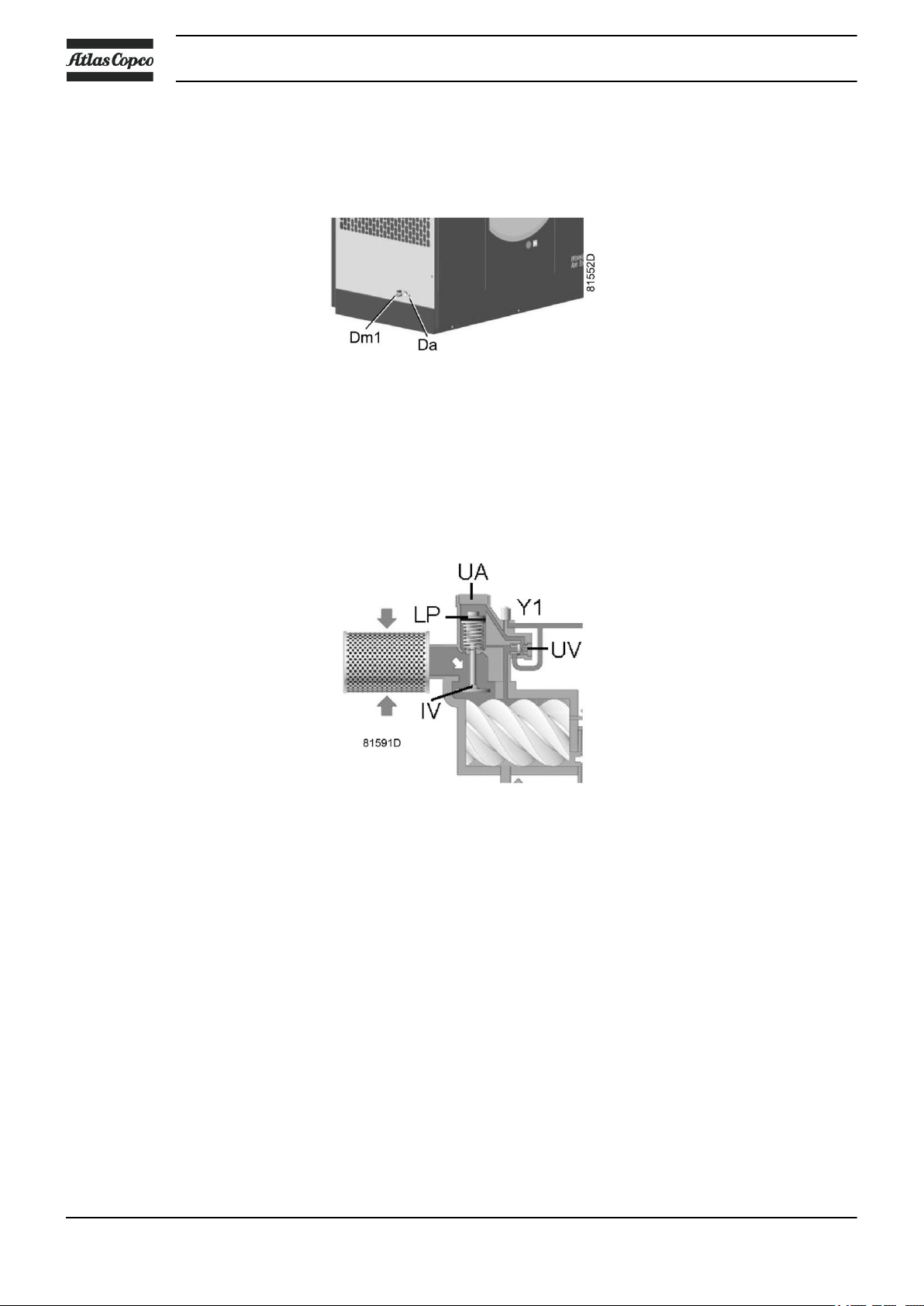
2.5 Condensate system
Condensate drains
The compressors have a condensate trap (MT) downstream the air cooler. The condensate trap is provided
with a manual drain outlet (Dm) and an automatic drain outlet (Da).
Instruction book
Condensate drain connections
2.6 Regulating system
Unloading valve assembly (loaded condition)
Description
If the consumption is less than the air output of the compressor, the net pressure increases. When the net
pressure is higher than the set-point (desired net pressure), the regulator will decrease the motor speed. If the
net pressure keeps on rising when the motor runs at minimum speed, the regulator stops the motor. If the
motor is stopped automatically and the net pressure approaches the set-point, the regulator will restart the
motor.
Unloaded operation
If the air consumption is less than the air output of the compressor, the net pressure increases. When the net
pressure reaches the unloading pressure, solenoid valve (Y1) is de-energised.
• The pressure above loading plunger (LP) and unloading valve (UV) is vented to atmosphere via solenoid
valve (Y1).
• Loading plunger (LP) moves upwards by spring force and causes inlet valve (IV) to close the air inlet.
14 2920 7104 10

Instruction book
• Unloading valve (UV) is opened by the pressure in the oil separator vessel. The pressure from the oil
separator vessel is released into atmosphere through the unloader (UA).
• The pressure in the oil separator vessel stabilises at low value. A reduced amount of air is compressed to
guarantee a minimal pressure, required for lubrication during unloaded operation.
Air output is stopped (0%), the compressor runs unloaded.
Loaded operation
When the net pressure is below the loading pressure, solenoid valve (Y1) is energised.
• Control pressure is fed from the oil separator vessel via solenoid valve (Y1) to loading plunger (LP) and
unloading valve (UV).
• Unloading valve (UV) closes the air blow-off opening. Loading plunger (LP) moves downwards and
causes inlet valve (IV) to open fully.
Air delivery is resumed (100%), the compressor runs loaded.
2.7 Electrical system
General
Also consult sections Electrical diagram and Electrical connections.
Components
Compressor cubicle
Reference Description
T1 Transformer
2920 7104 10 15
Reference Description
F1/2/3/4 Fuses
KL Line contactor
PE Earth terminal
El Elektronikon controller
S3 Emergency stop button
K2 Fan motor contactor
Q2 Fan motor circuit breaker
U1 Frequency converter
X12 CAN bus connector
SSA/SSB Service switch
Instruction book
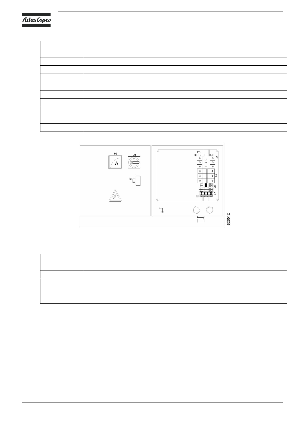
Reference Description
F6 Fuses
PE Earth terminal
Q1 Main switch
S1 Local / LAN switch
P3 Ammeter
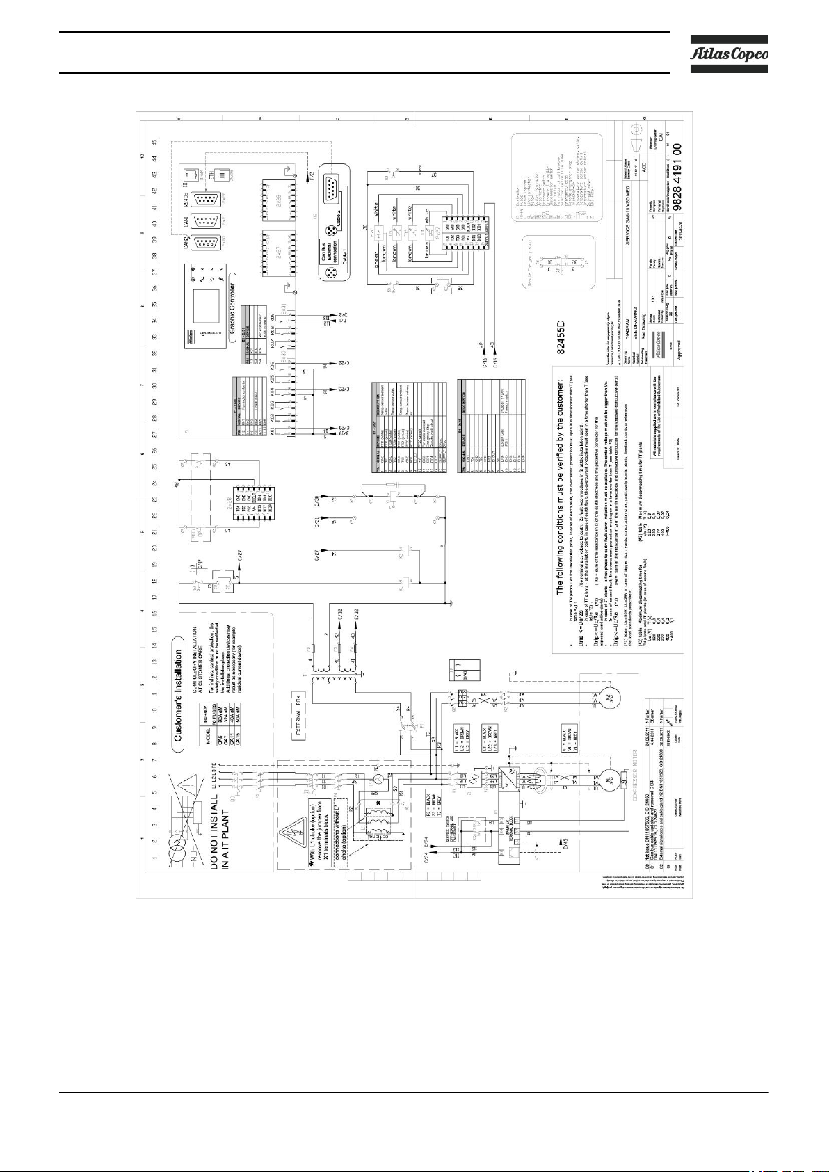
2.8 Electrical diagram
The complete electrical diagram can be found in the electric cubicle.
External box
16 2920 7104 10
Instruction book
Specific components
Pressure switch on oil separator vessel
This switch, referred to as FTGOL (Failed To Go On Load), gives feedback to the regulation system that
pressure is built up in the vessel when the compressor is loaded. It is a normally open switch, and it closes
when the pressure is above 2-3 bar.
Temperature sensor at outlet
2920 7104 10 17

Instruction book
This sensor measures the temperature of the compressed air after the cooler. It gives a warning when the
temperature exceeds 55°C, since this is not optimal for the dryer down the line.
Ammeter
The Ammeter in the cubicle door measures the current and allows to follow up unusual behaviour.
Main switch
The main switch allows to cut the power supply to the cubicle, during maintenance or during problem solving.
Local/LAN switch
A physical switch is mounted on the cubicle to enable easy switching to local control mode during maintenance
or for problem solving. When the switch is in LAN position, this compressor will be under control of the ESMED controller.
CAN port
On the side of the cubicle, two CAN connectors are foreseen for easy connecting of CAN cables towards the
ES-MED (the Plant Central Control Unit) or other compressors. When the compressor is last in line, the upper
CAN connector must be chosen and the dip switch on the CAN connector inside the cubicle must be switched
to ON.
2.9 Air receiver
The compressed air receiver ensures an instantaneous response to the demand for compressed air and prevents
continuous operation of the compressor during periods of light demand. The reservoir is a welded mild steel
construction, designed and tested in accordance with European Standard EN 286-1. Test details are annotated
on a plate permanently fixed to the reservoir and copies of the appropriate test certificates are supplied with
each plant. The reservoir incorporates access covers to facilitate future insurance internal inspection. Both
the interior and exterior are protected against corrosion with a hot dip galvanised finish. A zero loss electronic
drain valve is fitted to the vessel at the lowest point to enable the removal of any internal moisture, which
may form as condensation, there is also a tapping for a pressure gauge. The receiver connects to the
compressors and to the filter/dryer assembly by external pipe work. Although essentially designed as a
freestanding unit, the vessel feet are pre-drilled to enable the plant to be bolted down if required. The receiver
capacity is expressed as the water capacity in litres and HTM02-01/HTM2022 requires a minimum capacity
of 50% of the Average Continuous Demand of the Plant. In practice, to achieve economic manufacture,
specific vessel sizes are used with a range of compressor sizes, which results in some plant installations having
a larger vessel than is theoretically necessary.
18 2920 7104 10
Instruction book
3 Elektronikon® Graphic controller
3.1 General
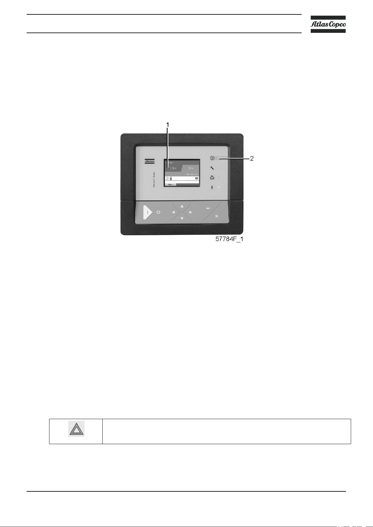
Control panel
Display of the Elektronikon® Graphic controller
Introduction
The Elektronikon controller has following functions:
• Controlling the compressor
• Protecting the compressor
• Monitoring components subject to service
• Automatic restart after voltage failure
Automatic control of the compressor operation
The regulator maintains the net pressure between programmable limits by automatically loading and unloading
the compressor. A number of programmable settings, e.g. the unloading and loading pressures, the minimum
stop time and the maximum number of motor starts are taken into account.
The regulator stops the compressor whenever possible to reduce the power consumption and restarts it
automatically when the net pressure decreases. In case the expected unloading period is too short, the
compressor is kept running to prevent too short standstill periods.
A number of time based automatic start/stop commands may be programmed. Take into
account that a start command will be executed (if programmed and activated), even after
manually stopping the compressor.
Protecting the compressor
Shut-down
2920 7104 10 19
Several sensors are provided on the compressor. If one of these measurements exceeds the programmed shutdown level, the compressor will be stopped. This will be indicated on display (1) and general alarm LED (2)
will blink.
Remedy the trouble and reset the message. See also the Inputs menu.
Shut-down warning
A shut-down warning level is a programmable level below the shut-down level.
If one of the measurements exceeds the programmed shut-down warning level, a message will appear on
display (1) and general alarm LED (2) will light up, to warn the operator that the shut-down warning level is
exceeded.
The message disappears as soon as the warning condition disappears.
Service warning
Instruction book
Before remedying, consult the applicable safety precautions.
A number of service operations are grouped (called Service Plans). Each Service Plan has a programmed time
interval. If a time interval is exceeded, a message will appear on display (1) to warn the operator to carry out
the service actions belonging to that Service Plan.
Automatic restart after voltage failure
The regulator has a built-in function to automatically restart the compressor if the voltage is restored after
voltage failure. This function is activated. If desired, the function can be deactivated. Consult Atlas Copco.
If activated and provided the regulator was in the automatic operation mode, the
compressor will automatically restart if the supply voltage to the module is restored!
20 2920 7104 10

Instruction book
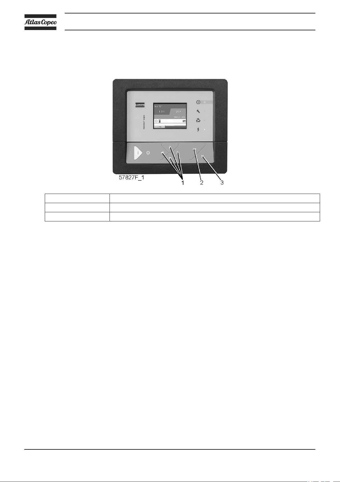
3.2 Control panel
Elektronikon regulator
Parts and functions
Reference Designation Function
1 Display Shows the compressor operating condition and a
2 Pictograph Automatic operation
3 Pictograph General alarm
4 General alarm LED Flashes if a shut-down warning condition exists.
5 Pictograph Service
6 Service LED Lights up if service is needed
7 Automatic operation LED Indicates that the regulator is automatically controlling
8 Voltage on LED Indicates that the voltage is switched on.
9 Pictograph Voltage on
10 Enter key Key to select the parameter indicated by the horizontal
11 Escape key To go to previous screen or to end the current action
12 Scroll keys Keys to scroll through the menu.
13 Stop button Button to stop the compressor. LED (7) goes out.
14 Start button Button to start the compressor. LED (7) lights up
Control panel
number of icons to navigate through the menu.
the compressor.
arrow. Only the parameters followed by an arrow
pointing to the right can be modified.
indicating that the Elektronikon regulator is operative.
2920 7104 10 21

3.3 Icons used
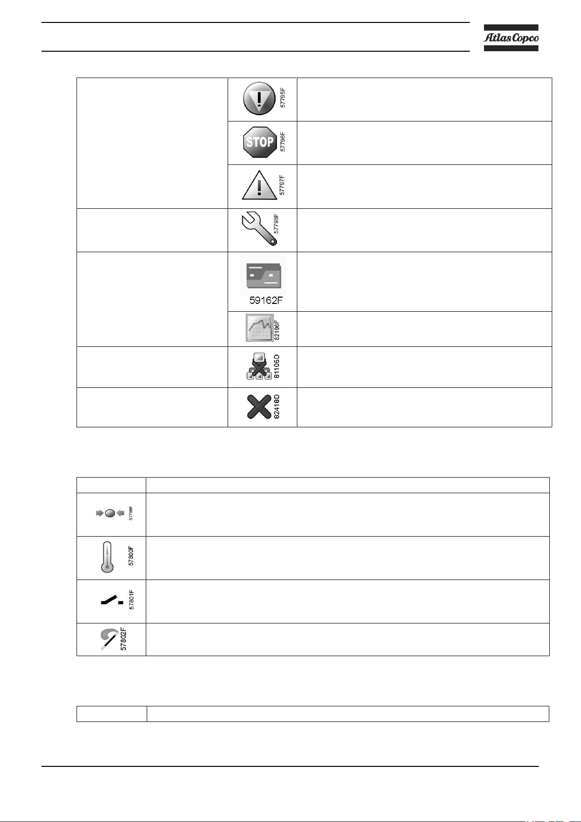
Status icons
Name Icon Description
Stopped / Running When the compressor is stopped, the icon stands still.
Compressor status Motor stopped
Instruction book
When the compressor is running, the icon is rotating.
Running unloaded
Running loaded
Machine control mode
or
Automatic restart after voltage
failure
Week timer Week timer is active
Local start / stop
Remote start / stop
Network control
Steady: LAN (network) control
Blinking: forced local control
Automatic restart after voltage failure is active
22 2920 7104 10
Instruction book
Active protection functions Emergency stop
Service Service required
Main screen display Value lines display icon
Shutdown
Warning
Chart display icon
General icons No communication / network problem
Not valid
Input icons
Icon Description
Pressure
Temperature
Digital input
Special protection
System icons
Icon Description
2920 7104 10 23
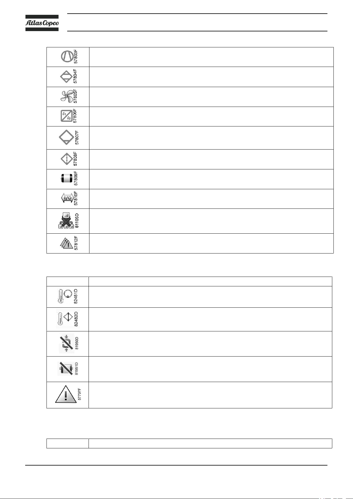
Compressor element (LP, HP, ...)
Dryer
Fan
Frequency converter
Drain
Filter
Motor
Failure expansion module
Instruction book
Network problem
General alarm
Specific icons on ES MED
Icon Description
Temperature element outlet
Temperature compressor outlet
Failed to go load: no pressure (>3bar) detected while compressor is loaded
Motor overload: motor draws too much current
No answer: compressor doesn’t respond to ES commands
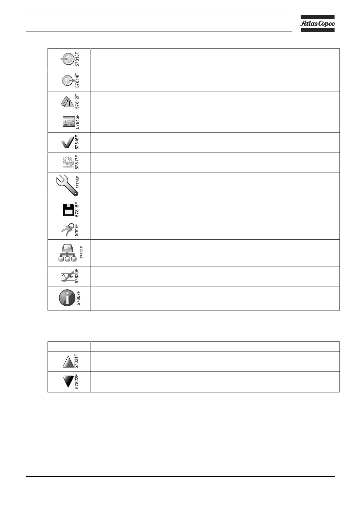
Menu icons
Icon Description
24 2920 7104 10
Instruction book
Inputs
Outputs
Alarms (Warnings, shutdowns)
Counters
Test
Settings
Service
Navigation arrows
Icon Description
Event history (saved data)
Access key / User password
Network
Setpoint
Info
Up
Down
2920 7104 10 25
3.4 Main screen
Control panel
Instruction book
(1) Scroll keys
(2) Enter key
(3) Escape key
Function
The Main screen is the screen that is shown automatically when the voltage is switched on and one of the
keys is pushed. It is switched off automatically after a few minutes when no keys are pushed.
Typically, 4 different main screen views can be chosen:
1. Two or four value lines
2. Chart (High resolution)
3. Chart (Medium resolution)
4. Chart (Low resolution)
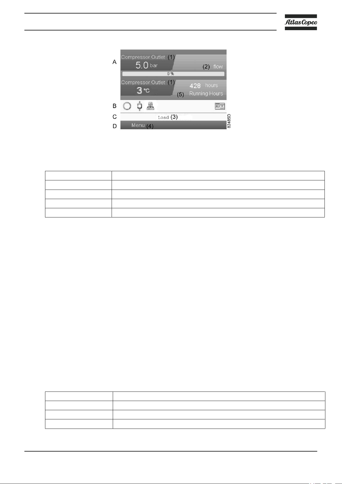
Two or four value lines screens
This type of Main screen shows the value of 2 or 4 parameters (see section Inputs menu). By default, the 4
value lines screen is activated.
26 2920 7104 10
Instruction book
Text on images
(1) Compressor Outlet
(2) Flow (compressors with frequency converter)
(3) Off, Load, Shutdown,... (text varies upon the compressors actual condition)
(4) Menu
(5) Running hours
Typical Main screen (4 value lines), GA MED with frequency converter
• Section A shows information regarding the compressor operation (e.g. the outlet pressure or the
temperature at the compressor outlet). On compressors with a frequency converter, the load degree (flow)
is given in % of the maximum flow.
• Section B shows Status icons. Following icon types are shown in this field:
• Fixed icons
These icons are always shown in the main screen and cannot be selected by the cursor (e.g. Compressor
stopped or running, Compressor status (running, running unloaded or motor stopped).
• Optional icons
These icons are only shown if their corresponding function is activated (e.g. week timer, automatic
restart after voltage failure , etc.)
• Pop up icons
These icons pop up if an abnormal condition occurs (warnings, shutdowns, service,...)
To call up more information about the icons shown, select the icon concerned using the scroll keys and
press the enter key.
• Section C is called the Status bar
This bar shows the text that corresponds to the selected icon.
• Section D shows the Action buttons. These buttons are used:
• To call up or program settings
• To reset a motor overload, service message or emergency stop
• To have access to all data collected by the regulator
The function of the buttons depends on the displayed menu. The most common functions are:
Designation Function
Menu To go to the menu
Modify To modify programmable settings
Reset To reset a timer or message
2920 7104 10 27
To activate an action button, highlight the button by using the Scroll keys and press the Enter key.
To go back to the previous menu, press the Escape key.
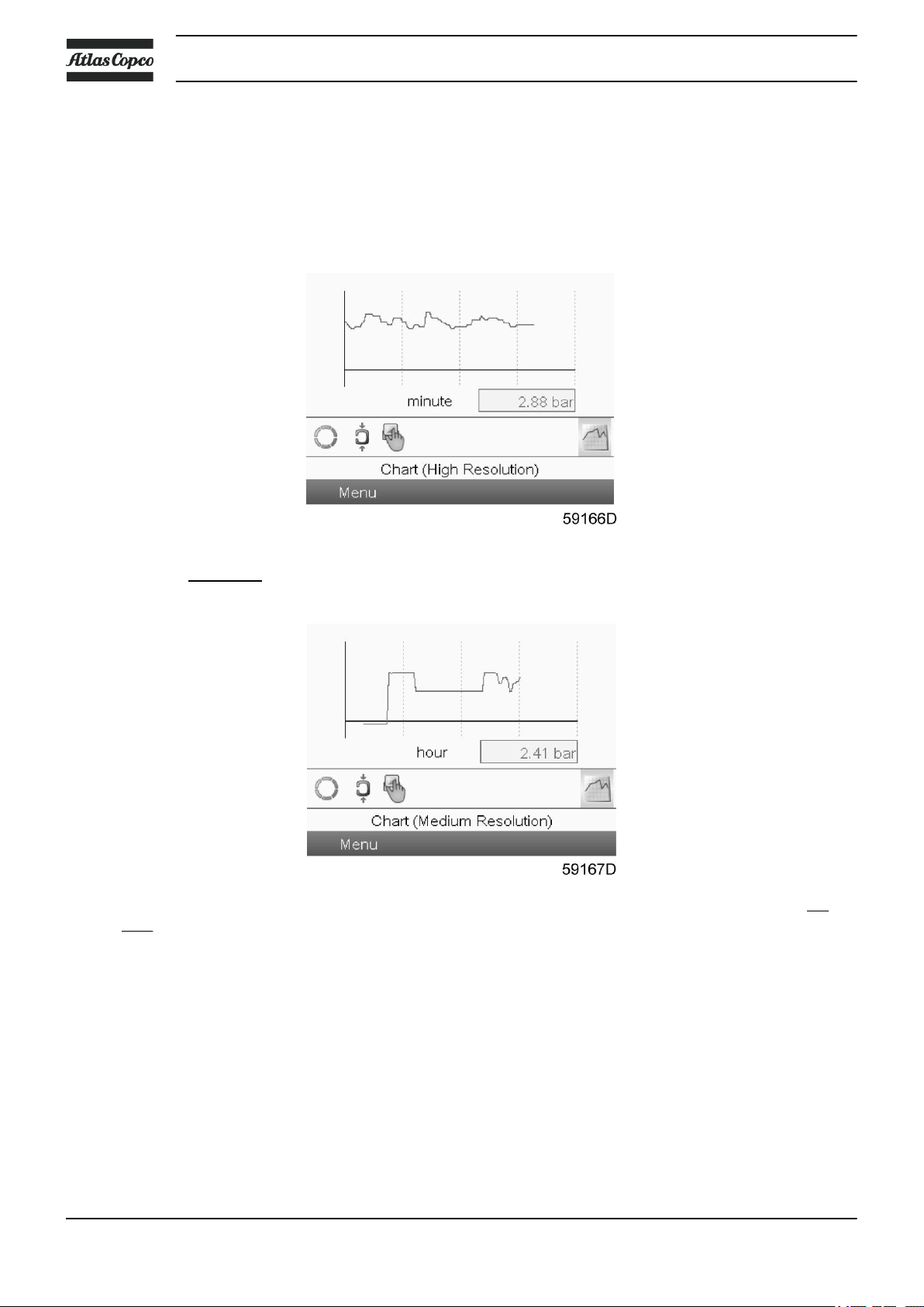
Chart views
Instead of viewing values, it is also possible to view a graph of one of the input signals (see section Inputs
menu) in function of the time.
Instruction book
When Chart (High Resolution) is selected, the chart shows the variation of the selected input (in this case the
pressure)
per minute. Also the instantaneous value is displayed. The screen shows the last 4 minutes.
The switch button (icon) for selecting other screens is changed into a small Chart and is highlighted (active).
When the Chart (Medium Resolution) is selected, the chart shows the variation of the selected input per
hour. The screen shows the last 4 hours.
28 2920 7104 10
 Loading...