

Atlas Copco FD450, FD300, FD380, FD260, FD700 Instruction Book
...
Atlas Copco Air Dryers
FD(W)260, -300, -380, -450, -700
Instruction Book
Important:
This book applies exclusively to FD dryers as from following serial numbers onwards and filled with
refrigerant R404a; see data plate:
FD260: AIQ-124 045
FD300: AIQ-140 200
FD380: AIQ-129 800
FD450: AIQ-140 550
FD700: AIQ-750 005
This instruction book meets the requirements for instructions specified by the machinery
directive 89/392/EEC and is valid for CE as well as non-CE labelled machines
No. 2920 1351 01
Registration code: APC FD / 38 / 988
Replaces No. 2920 1351 00 and for FD700 only 2920 1371 00
1998-03
*2920135101*

Instruction book
This instruction book describes how to handle and operate the subject machine(s) to ensure safe operation, optimum working
economy and long service life.
Read this book before putting the machine into operation to ensure correct handling, operation and proper maintenance from
the beginning. The maintenance schedule contains a summary of the measures for keeping the dryer in good repair. The
maintenance procedures are simple but must be carried out regularly.
Keep the book available for the operator(s) and make sure that the dryer is operated and that the maintenance actions are carried
out according to the instructions. Record all operating data, maintenance work effected, etc. in an operator's logbook available
from Atlas Copco. Follow all applicable safety precautions, amongst others those mentioned on the cover of this book.
Repair operations must be performed by trained personnel from Atlas Copco, who can also be contacted if any further information
is desired.
In all correspondence always mention the dryer type and the complete serial number, shown on the data plate.
For all specific data not mentioned in the text, consult section "Principal data".
The company reserves the right to make changes without prior notice.
Contents
Page
1 Leading particulars . . . . . . . . . . . . . . . . . . . . . . . . . . . 3
1.1 General description. . . . . . . . . . . . . . . . . . . . . . . . . 3
1.2 Air circuit . . . . . . . . . . . . . . . . . . . . . . . . . . . . . . . . 3
1.3 Refrigeration circuit . . . . . . . . . . . . . . . . . . . . . . . . 5
1.4 Automatic regulation system . . . . . . . . . . . . . . . . . 8
1.5 Electrical system . . . . . . . . . . . . . . . . . . . . . . . . . . . 8
2 Installation. . . . . . . . . . . . . . . . . . . . . . . . . . . . . . . . . . . 8
2.1 Dimension drawings . . . . . . . . . . . . . . . . . . . . . . . . 8
2.2 Installation proposal . . . . . . . . . . . . . . . . . . . . . . . 13
2.3 Installation instructions. . . . . . . . . . . . . . . . . . . . . 13
2.4 Pictographs . . . . . . . . . . . . . . . . . . . . . . . . . . . . . . 14
3 Operating instructions . . . . . . . . . . . . . . . . . . . . . . . . 15
3.1 Initial start. . . . . . . . . . . . . . . . . . . . . . . . . . . . . . . 15
3.2 Starting . . . . . . . . . . . . . . . . . . . . . . . . . . . . . . . . . 15
3.3 During operation . . . . . . . . . . . . . . . . . . . . . . . . . . 16
2
Page
3.4 Stopping . . . . . . . . . . . . . . . . . . . . . . . . . . . . . . . . 16
3.5 Possible causes of unstable or too high pressure
dewpoint temperature . . . . . . . . . . . . . . . . . . . . . . 16
4 Maintenance . . . . . . . . . . . . . . . . . . . . . . . . . . . . . . . . 16
5 Settings . . . . . . . . . . . . . . . . . . . . . . . . . . . . . . . . . . 17
5.1 Automatic expansion valve. . . . . . . . . . . . . . . . . . 17
5.2 Switches . . . . . . . . . . . . . . . . . . . . . . . . . . . . . . . . 17
6 Problem solving. . . . . . . . . . . . . . . . . . . . . . . . . . . . . . 18
7 Principal data . . . . . . . . . . . . . . . . . . . . . . . . . . . . . . . 19
7.1 Limitations/nominal conditions . . . . . . . . . . . . . . 19
7.2 Specific data . . . . . . . . . . . . . . . . . . . . . . . . . . . . . 19
8 Conversion list of SI units into British/US units . . . 20
2920 1351 01

Instruction book
1 LEADING PARTICULARS
1.1 General description
The FD air dryers remove moisture from compressed air by
cooling the air to near freezing point. This causes water and
oil to condense. The condensate is automatically drained. The
air is warmed up before leaving the dryer.
On air-cooled dryers, the condenser has a cooling fan controlled
by a condenser pressure switch. W ater-cooled dryers have an
automatic regulating valve in the water outlet of the condenser.
FD260 up to -700 are air-cooled, while FD260 W up to -700
W are water-cooled dryers. The suffix W is not mentioned
further in the book where the descriptions are valid for both
air- and water-cooled dryers.
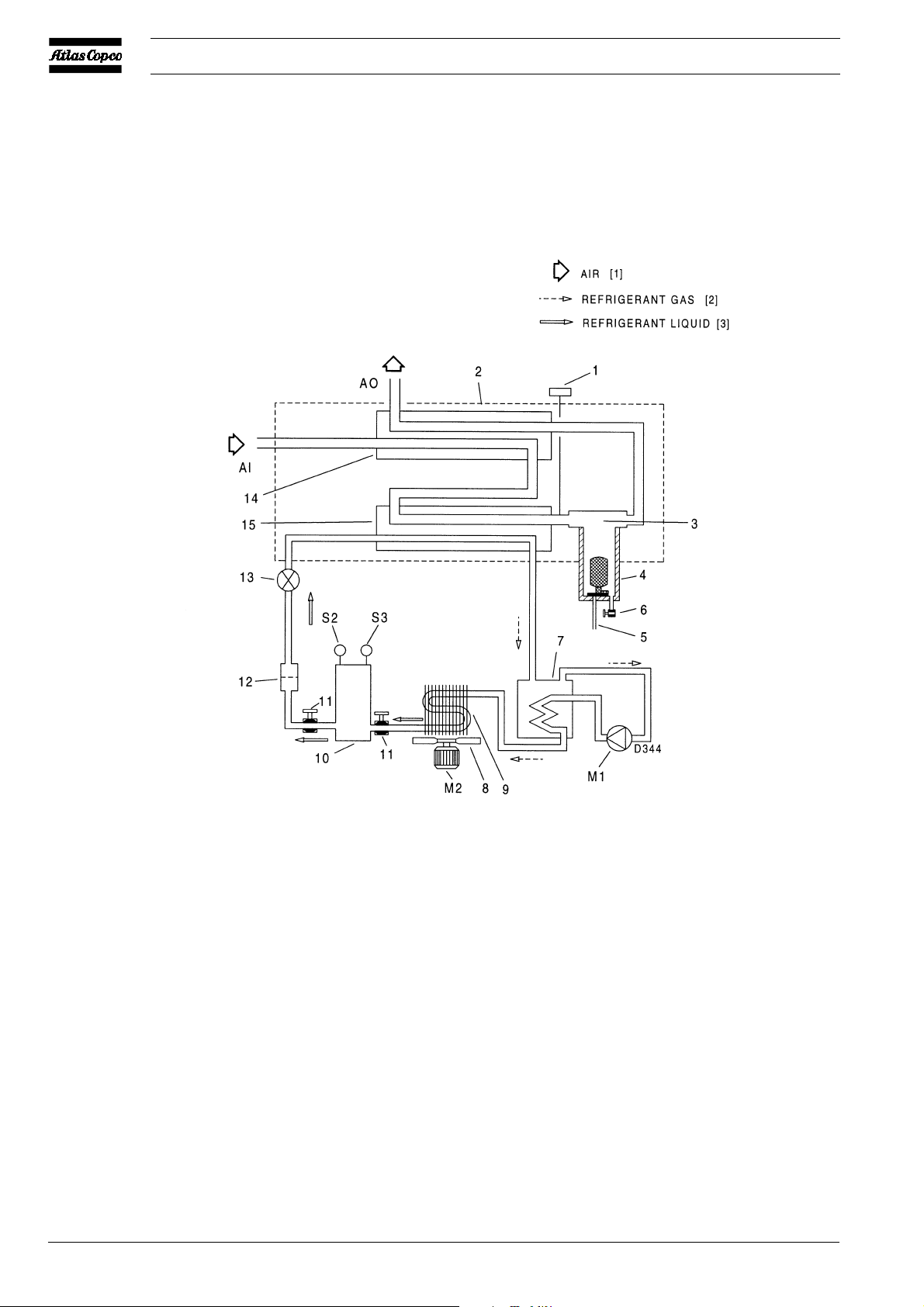
1.2 Air circuit (Fig. 2)
Compressed air enters air/air heat exchanger (14) and is precooled by the outgoing, cold, dried air. Water and oil in the
incoming air start to condense. The air then flows through air/
refrigerant heat exchanger/evaporator (15) where the refrigerant
evaporates and withdraws heat from the air. This cools the air
to close to the evaporating temperature of the refrigerant. More
water and oil in the air condense. The cold air then flows
through separator (3) where all the condensate is separated from
the air. The condensate collects in condensate trap (4) and is
automatically drained. From separator (3) the cold dried air
flows through air/air heat exchanger (14), where it is warmed
up by the incoming air to approx. 10°C (18°F) below the
incoming air temperature. Reheating the dried air reduces its
relative humidity, so that condensation in the air net cannot
occur unless the air is cooled to below the pressure dewpoint
temperature indicated by gauge (1).
2920 1351 01
F6837
Fig. 1. Front view of FD450
3
Instruction book
AI. Air inlet connection
AO. Air outlet connection
M1. Refrigerant compressor/motor
M2. Condenser cooling fan motor
S2. High pressure shut-down switch
S3. Fan control switch
1. Pressure dewpoint temperature
gauge
Fig. 2. Air and refrigerant flow diagram, air-cooled dryers
4
2. Insulating block
3. Cyclone condensate separator
4. Condensate trap with automatic
discharge
5. Automatic condensate drain hose
6. Manual condensate drain valve
7. Liquid separator
8. Fan
9. Refrigerant condenser
10. Liquid refrigerant receiver
11. Refrigerant shut-off valve
12. Liquid refrigerant dryer/filter
13. Refrigerant expansion valve
14. Air/air heat exchanger
15. Air/refrigerant heat exchanger/
evaporator
2920 1351 01
Instruction book
1.3 Refrigeration circuit (Fig. 2)
Compressor (M1) delivers hot, high-pressure refrigerant gas,
which flows, via the coil of liquid separator (7), through
condenser (9) where most of the refrigerant condenses. On
air-cooled condensers, a fan control switch (S3) stops and starts
the fan motor (M2) at falling or rising condenser pressure. On
water-cooled condensers, an automatic valve (3-Figs. 5)
regulates the cooling water flow, thus controlling the
temperature, which is directly dependent on the pressure. The
cooled refrigerant then collects in receiver (10).
The liquid leaves the receiver (10) via its syphon outlet and
flows through liquid refrigerant filter/dryer (12) to expansion
valve (13) where it expands to evaporating pressure.
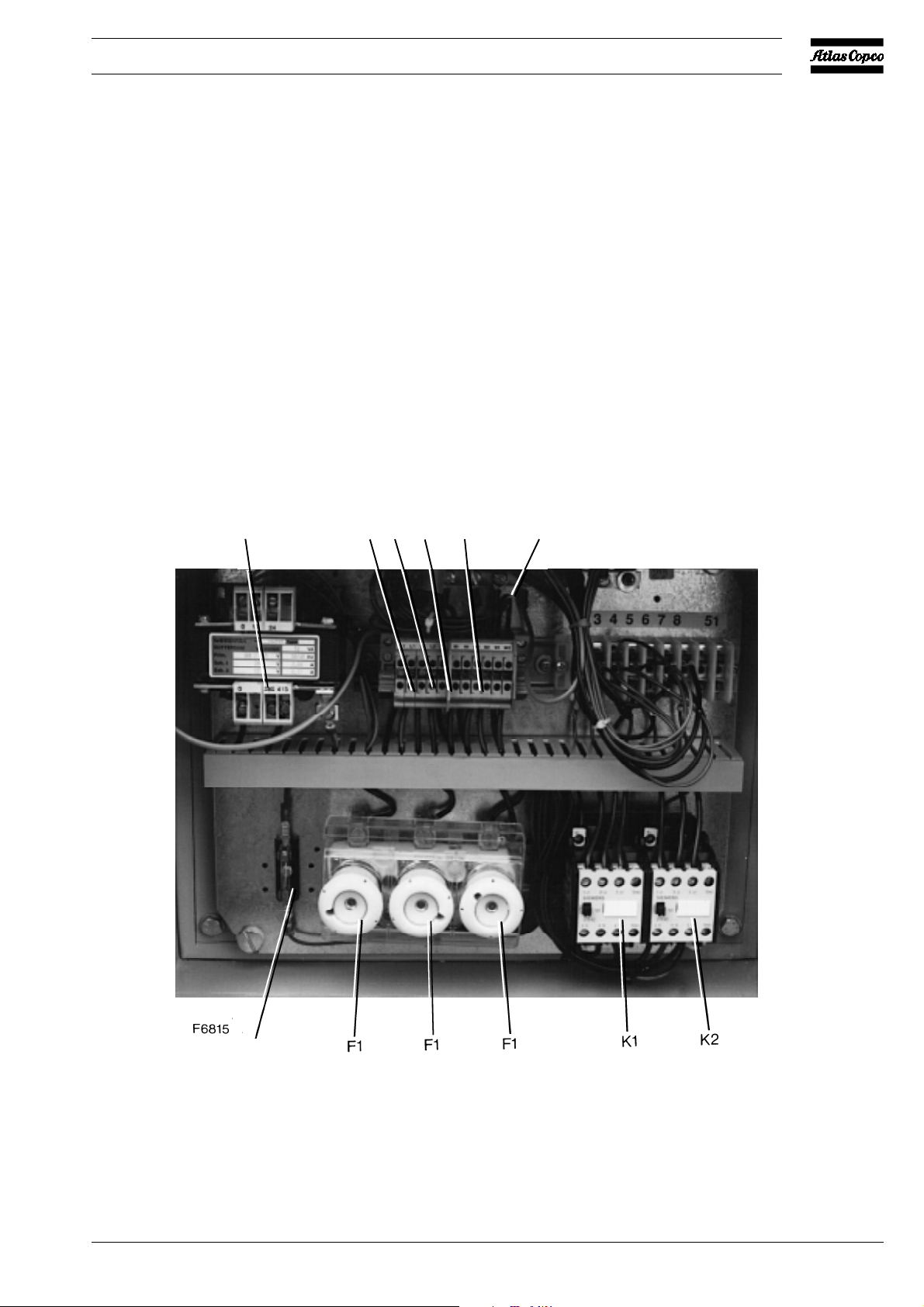
T1 L1 L2 L3 1X1 PE
In expansion valve (13) some of the expanding liquid refrigerant
evaporates, for which the required heat is withdrawn from the
refrigerant itself.
The refrigerant enters the heat exchanger/evaporator (15) where
it withdraws heat from the compressed air by further
evaporation. Dependent on the compressed air load, all, or
almost all, refrigerant evaporates at constant pressure and
temperature. The vapour refrigerant leaving evaporator (15)
flows into liquid separator (7). The liquid separator prevents
any droplets from entering compressor (M1) because warm
refrigerant, leaving the compressor, flows through the coil of
the liquid separator and evaporates the surrounding liquid.
From liquid separator (7) the refrigerant gas is sucked in by the
compressor.
2920 1351 01
F2
F1. Fuses, fan motor
F2. Fuse, secondary side (24 V) of transformer
K1. Motor contactor, refrigerant compressor
K2. Motor contactor, condenser cooling fan
Fig. 3. Electric cubicle of FD260
L1/3. T erminal, mains
PE. Earth terminal
T1. T ransformer
1X1. T erminal strip
5
Instruction book
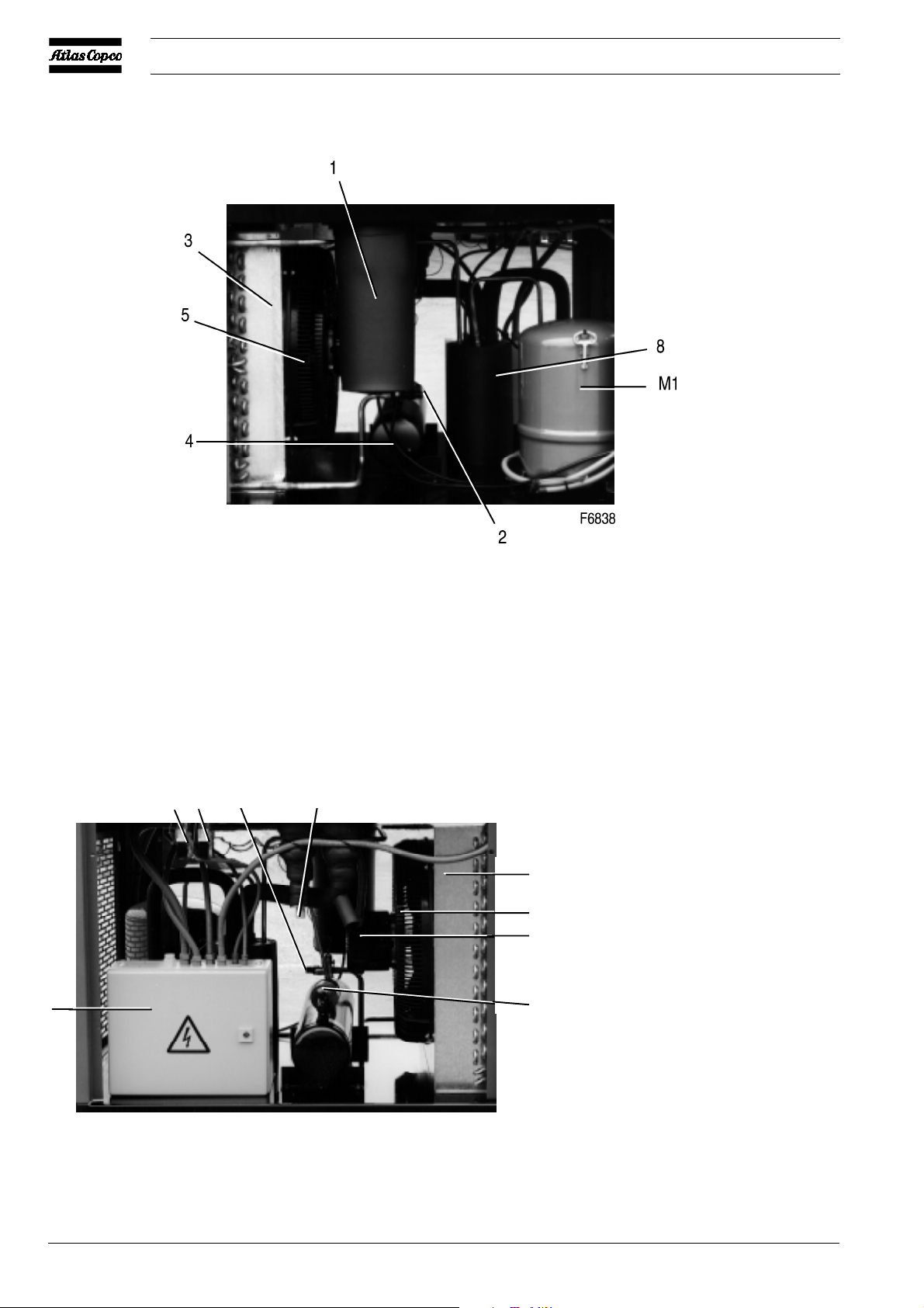
Fig. 4a
S3 S2 2 7
3
5
M2
M1. Refrigerant compressor/motor
M2. Condenser cooling fan motor
S2. High pressure shut-down switch
S3. Fan control switch
9
6
1. Condensate trap with automatic
discharge
2. Refrigerant shut-off valve
3. Condenser
4. Liquid refrigerant receiver
5. Fan
F6839
6. Refrigerant dryer/filter
7. Refrigerant expansion valve
8. Liquid separator
9. Electric cubicle
Fig. 4b
6
Figs. 4. Side views of FD450
2920 1351 01
 Loading...