

Atlas Copco FD90, FD110, FD130, FD170, FD230 Instruction Booklet

Atlas Copco Air dryers
No. 2920 1390 02
Replaces No. 2920 1390 01
Registration code: APC FD / 38 / 975
2001-12
FD90, FD110, FD130, FD170 and FD230
Instruction book
Web-site: http://www.atlascopco-compressors.com
·
Copyright 2001, Atlas Copco Airpower n.v., Antwerp, Belgium.
Any unauthorized use or copying of the contents or any part thereof is prohibited. This
applies in particular to trademarks, model denominations, part numbers and drawings.
·
This instruction book meets the requirements for instructions specified by the machinery
directive 98/37/EC and is valid for CE as well as non-CE labelled machines.

2920 1390 02
2
Instruction book
This instruction book describes how to handle and operate the subject machine(s) to ensure safe operation, optimum working
economy and long service life.
Read this book before putting the machine into operation to ensure correct handling, operation and proper maintenance from
the beginning. The maintenance schedule contains a summary of the measures for keeping the dryer in good repair. The
maintenance procedures are simple but must be carried out regularly.
Keep the book available for the operator(s) and make sure that the dryer is operated and that the maintenance actions are carried
out according to the instructions. Record all operating data, maintenance work effected, etc. in an operator's logbook available
from Atlas Copco. Follow all applicable safety precautions, amongst others those mentioned in this book.
Repair operations should be performed by trained personnel from Atlas Copco who can also be contacted if any further information
is desired.
In all correspondence always mention the dryer type and the complete serial number, shown on the data plate.
For all specific data not mentioned in the text, consult sections "Maintenance" and "Principal data".
The company reserves the right to make changes without prior notice.
Page
3.2 Starting . . . . . . . . . . . . . . . . . . . . . . . . . . . . . . . . . 13
3.3 During operation . . . . . . . . . . . . . . . . . . . . . . . . . . 14
3.4 Stopping . . . . . . . . . . . . . . . . . . . . . . . . . . . . . . . . 14
4 Maintenance . . . . . . . . . . . . . . . . . . . . . . . . . . . . . . . . 14
5 Settings . . . . . . . . . . . . . . . . . . . . . . . . . . . . . . . . . . . . . 14
6 Problem solving. . . . . . . . . . . . . . . . . . . . . . . . . . . . . . 14
7 Principal data . . . . . . . . . . . . . . . . . . . . . . . . . . . . . . . 15
7.1 Limitations/nominal conditions . . . . . . . . . . . . . . 15
7.2 Specific data of FD90, FD110 and FD130. . . . . . 15
7.3 Specific data of FD170 and FD230 . . . . . . . . . . . 16
8 Conversion list of SI units into British units . . . . . . 16
Contents
Page
1 Leading particulars . . . . . . . . . . . . . . . . . . . . . . . . . . . 3
1.1 General description . . . . . . . . . . . . . . . . . . . . . . . . . 3
1.2 Air circuit . . . . . . . . . . . . . . . . . . . . . . . . . . . . . . . . 3
1.3 Refrigeration circuit . . . . . . . . . . . . . . . . . . . . . . . . 3
1.4 Automatic regulation system . . . . . . . . . . . . . . . . . 4
1.5 Electrical system . . . . . . . . . . . . . . . . . . . . . . . . . . . 4
2 Installation. . . . . . . . . . . . . . . . . . . . . . . . . . . . . . . . . . . 9
2.1 Dimension drawings . . . . . . . . . . . . . . . . . . . . . . . . 9
2.2 Installation proposal . . . . . . . . . . . . . . . . . . . . . . . 11
2.3 Installation instructions . . . . . . . . . . . . . . . . . . . . 12
2.4 Pictographs . . . . . . . . . . . . . . . . . . . . . . . . . . . . . . 13
3 Operating instructions . . . . . . . . . . . . . . . . . . . . . . . . 13
3.1 Initial start . . . . . . . . . . . . . . . . . . . . . . . . . . . . . . . 13
2920 1390 02
3
Instruction book
1 LEADING PARTICULARS
1.1 General description
The FD air dryers remove moisture from compressed air by
cooling the air to near freezing point. This causes water to
condense. The condensate is automatically drained. The air is
warmed up before leaving the dryer.
1.2 Air circuit (Fig. 1.2)
Compressed air enters heat exchanger (13) and is cooled by
the outgoing, cold, dried air. Water in the incoming air starts to
condense. The air then flows through heat exchanger/
evaporator (11) where the refrigerant evaporates causing the
air to be further cooled to close to the evaporating temperature
of the refrigerant. More water in the air condenses. The cold
air then flows through separator (3) where all the condensate
is separated from the air. The condensate collects in condensate
trap (4) and is automatically drained. The cold, dried air flows
through heat exchanger (13), where it is warmed up by the
incoming air to approx. 10 degrees Celsius below the incoming
air temperature. Condensation in the air net cannot occur unless
the air is cooled to below the pressure dewpoint indicated by
gauge (1).
1.3 Refrigeration circuit (Fig. 1.2)
Compressor (M1) delivers hot, high-pressure refrigerant gas
which flows through condenser (9) where most of the refrigerant
condenses.
The liquid flows through liquid refrigerant dryer/filter (12) to
capillary tube (7). The refrigerant leaves the capillary tube at
evaporating pressure.
The refrigerant enters evaporator (11) where it withdraws heat
from the compressed air by further evaporation at constant
pressure. The heated refrigerant leaves the evaporator and is
sucked in by the compressor via accumulator (14).
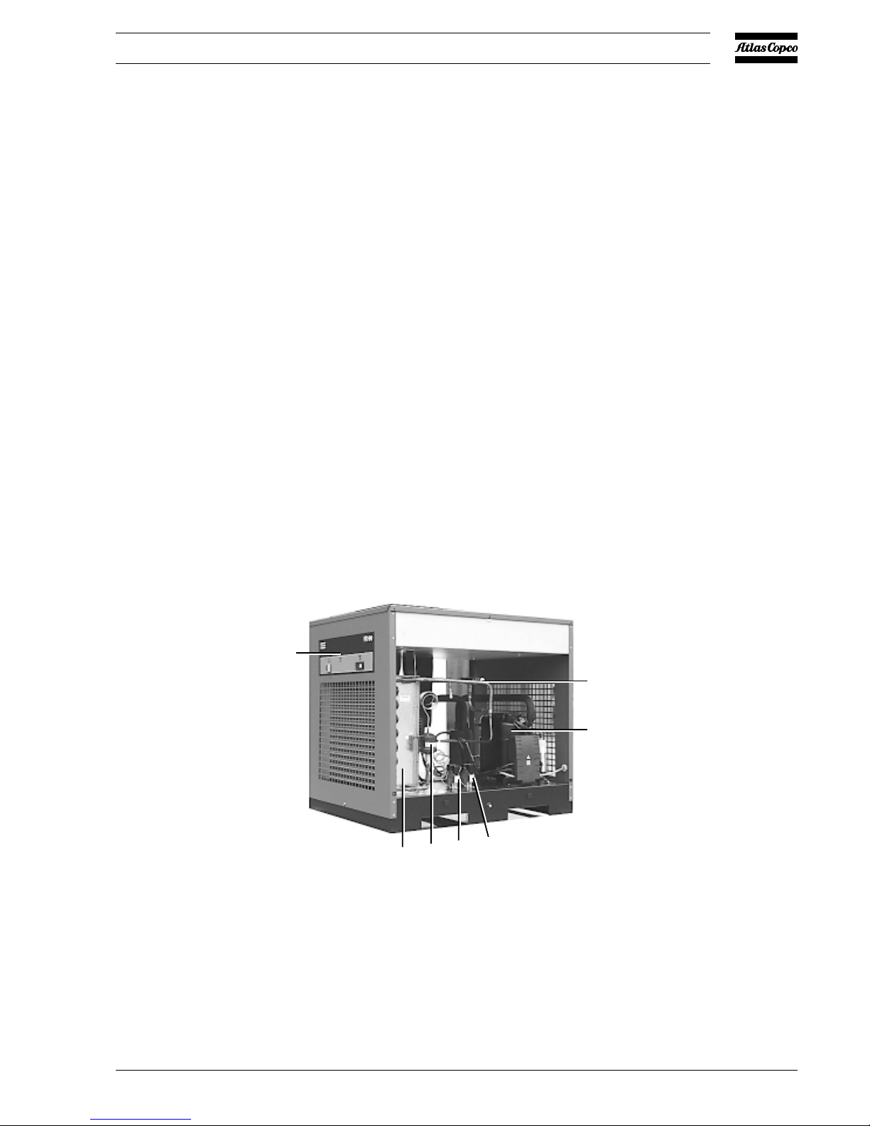
M1. Refrigerant compressor
S3. Fan control switch
S7. High pressure shut down switch
1. Control panel
2. Condenser
3. Hot gas by-pass valve
4. Liquid refrigerant dryer/filter
Fig. 1.1 General view of FD90
2
4
S7
S3
1
3
M1
50643F

2920 1390 02
4
Instruction book
AI. Wet air inlet
AO. Dry air outlet
M1. Refrigerant compressor
M2. Condenser fan motor
S3. Fan control switch
S7. High pressure shut down switch
1. Pressure dewpoint gauge
2. Insulating block
3. Condensate separator
4. Condensate trap
5. Automatic condensate drain hose
6. Manual condensate drain valve
7. Capillary tube
8. Condenser cooling fan
9. Refrigerant condenser
10. Hot gas by-pass valve
11. Air/refrigerant heat exchanger/
evaporator
12. Liquid refrigerant dryer/filter
13. Air/air heat exchanger
14. Accumulator
Fig. 1.2 Air and refrigerant flow diagram
1.4 Automatic regulation system (Fig. 1.2)
The condenser pressure must be kept as constant as possible
to obtain stable operation, therefore, fan control switch (S3)
stops and starts the cooling fan.
When, at partial or no load, the evaporator pressure drops to
2.25 bar(e), the by-pass regulator opens and hot, high pressure
gas is fed to the evaporator circuit to prevent the evaporator
pressure from dropping any further.
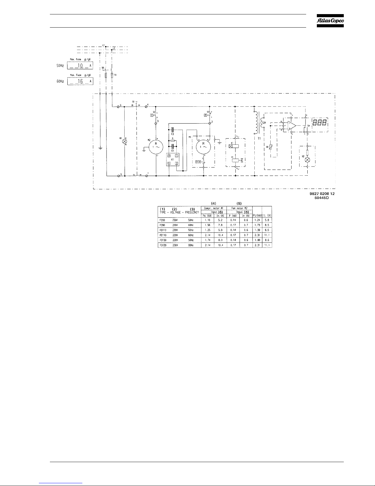
1.5 Electrical system (Figs. 1.3 up to 1.6)
FD170 60Hz and FD230 60Hz dryers are 3-phase units, all other
FD dryers are single-phase units.
The refrigerant compressors (M1) of FD170 and FD230 dryers
are equipped with a crankcase heater (Rs). When voltage is
supplied, the heater is energized. It keeps the oil in the crankcase
warm to prevent condensing of refrigerant in the compressor
housing, which could result in serious damage of the compressor
at start (liquid knock).
2920 1390 02
5
Instruction book
Fan control switch (S3) starts fan motor (M2) as soon as the
condenser pressure reaches the upper set point of the switch
and will stop the fan motor when the condenser pressure
decreases to its lower set point.
High pressure shut-down switch (S7-Fig. 1.1) stops the
compressor motor when the pressure in the refrigerant circuit
reaches the upper set point of the switch. After tripping, it
must be reset manually by pressing its reset knob.
The compressor motor has a built-in thermic protection. If the
compressor motor stops without apparent reason, it will
probably be the thermic protection which has tripped. In such
case, the compressor will restart when the motor windings have
cooled down, which may take up to 2 hours.
C1. Start capacitor
C3. Run capacitor
F0. Main fuses, local installation
(customer's installation)
H1. Indicator lamp, VOLTAGE ON
H2. Indicator lamp, DEWPOINT
ALARM (optional)
K1. Timer (optional)
M1. Compressor motor
M2. Condenser fan motor
R. Resistor
R1. Temperature sensor, dewpoint
(optional)
S0. Main switch (customer's
installation)
S1. Button, ON-OFF
S3. Fan control switch
S4. Electronic thermostat with
display (optional)
S7. High pressure shut down switch
T1. Transformer (optional)
Y1. Solenoid valve, interval drain
(optional)
Fig. 1.3 Electrical diagram of FD90 up to FD130
 Loading...