

Atlas Copco FD560, FD700, FD1600, FDW560, FDW700 Instruction Book
...
Instruction book for
Air dryers
FD(W)560, -700, -850, -950,
-1200, -1600
This instruction book applies exclusively to FD560, -700, -850, -950, -1200
and -1600 dryers filled with R404a refrigerant (see data plate)
Registration code
Collection: APC FD
Tab: 38
Sequence: 987
No. 2920 1371 00
1997-12
This instruction book meets the requirements for instructions specified by the
machinery directive 89/392/EEC and is valid for CE as well as non-CE labelled
machines
Oil-free Air Division - B-2610 Wilrijk - Belgium
*2920137100*

Oil-free Air Division Instruction book
This instruction book describes how to handle and operate the subject machine(s) to ensure safe operation, optimum working
economy and long service life.
Read this book before putting the machine into operation to ensure correct handling, operation and proper maintenance
from the beginning. The maintenance schedule contains a summary of the measures for keeping the dryer in good repair. The
maintenance procedures are simple but must be carried out regularly.
Keep the book available for the operator(s) and make sure that the dryer is operated and that the maintenance actions are
carried out according to the instructions. Record all operating data, maintenance work effected, etc. in an operator's logbook
available from Atlas Copco. Follow all applicable safety precautions, amongst others those mentioned on the cover of this
book.
Repair operations must be performed by trained personnel from Atlas Copco, who can also be contacted if any further
information is desired.
In all correspondence always mention the dryer type and the complete serial number, shown on the data plate.
For all specific data not mentioned in the text, consult section "Principal data".
The company reserves the right to make changes without prior notice.
CONTENTS
Page
1 Leading particulars . . . . . . . . . . . . . . . . . . . . . . . . . . . 3
1.1 General description. . . . . . . . . . . . . . . . . . . . . . . . . 3
1.2 Air circuit . . . . . . . . . . . . . . . . . . . . . . . . . . . . . . . . 3
1.3 Refrigeration circuit . . . . . . . . . . . . . . . . . . . . . . . . 5
1.4 Automatic regulation system . . . . . . . . . . . . . . . . . 5
1.5 Electrical system. . . . . . . . . . . . . . . . . . . . . . . . . . . 5
2 Installation. . . . . . . . . . . . . . . . . . . . . . . . . . . . . . . . . . 10
2.1 Dimension drawings . . . . . . . . . . . . . . . . . . . . . . . 10
2.2 Installation proposal . . . . . . . . . . . . . . . . . . . . . . . 17
2.3 Installation instructions. . . . . . . . . . . . . . . . . . . . . 17
2.4 Pictographs . . . . . . . . . . . . . . . . . . . . . . . . . . . . . . 19
3 Operating instructions . . . . . . . . . . . . . . . . . . . . . . . . 19
3.1 Initial start. . . . . . . . . . . . . . . . . . . . . . . . . . . . . . . 19
3.2 Starting . . . . . . . . . . . . . . . . . . . . . . . . . . . . . . . . . 19
3.3 During operation. . . . . . . . . . . . . . . . . . . . . . . . . . 20
2
Page
3.4 Stopping . . . . . . . . . . . . . . . . . . . . . . . . . . . . . . . . 20
3.5 Possible causes of unstable or too high pressure
dewpoint temperature . . . . . . . . . . . . . . . . . . . . . . 20
4 Maintenance . . . . . . . . . . . . . . . . . . . . . . . . . . . . . . . . 21
5 Settings . . . . . . . . . . . . . . . . . . . . . . . . . . . . . . . . . . 21
5.1 Automatic expansion valve. . . . . . . . . . . . . . . . . . 21
5.2 Switches . . . . . . . . . . . . . . . . . . . . . . . . . . . . . . . . 21
6 Problem solving. . . . . . . . . . . . . . . . . . . . . . . . . . . . . . 22
7 Principal data . . . . . . . . . . . . . . . . . . . . . . . . . . . . . . . 23
7.1 Limitations/nominal conditions . . . . . . . . . . . . . . 23
7.2 Specific data . . . . . . . . . . . . . . . . . . . . . . . . . . . . . 23
8 Conversion list of SI units into British/US units . . . 24
2920 1371 00
Instruction book Oil-free Air Division
1 LEADING PARTICULARS
Note: Fig. 2 shows the air and refrigerant flow diagram of
FD560 and FD700. The flow diagram of FD850 up to FD1600
looks similar, but these dryers are provided with two condensate
separators and two liquid separators. The description below is
valid for all dryers described in this book.
1.1 General description
The FD air dryers remove moisture from compressed air by
cooling the air to near freezing point. This causes water and
oil to condense. The condensate is automatically drained. The
air is warmed up before leaving the dryer.
On air-cooled dryers, the condenser has a cooling fan controlled
by a condenser pressure switch. W ater-cooled dryers have an
automatic regulating valve in the water outlet of the condenser.
FD560 up to -950 are air-cooled, while FD560 W up to -1600
W are water-cooled dryers. The suffix W is not mentioned
further in the book where the descriptions are valid for both
air- and water-cooled dryers.
1.2 Air circuit (Fig. 2)
Compressed air enters air/air heat exchanger (16) and is precooled by the outgoing, cold, dried air. Water and oil in the
incoming air start to condense. The air then flows through air/
refrigerant heat exchanger/evaporator (15) where the refrigerant
evaporates and withdraws heat from the air. This cools the air
to close to the evaporating temperature of the refrigerant. More
water and oil in the air condense. The cold air then flows
through separator(s) (3) where all the condensate is separated
from the air. The condensate collects in condensate trap (4)
and is automatically drained. From separator(s) (3) the cold
dried air flows through air/air heat exchanger (16), where it
2920 1371 00
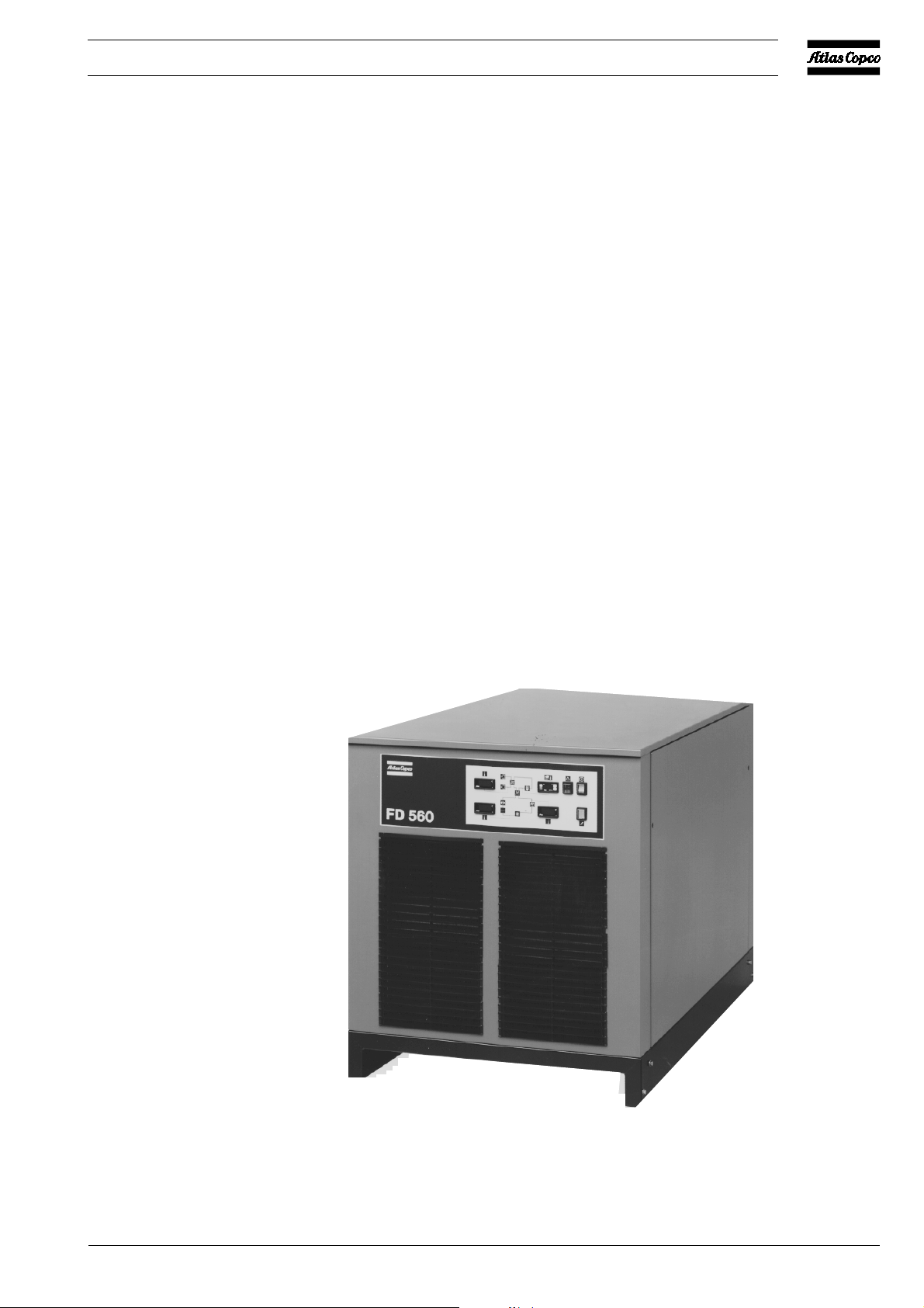
50149F
Fig. 1. General view of FD560
3

Oil-free Air Division Instruction book
AI. Air inlet connection
AO. Air outlet connection
M1. Refrigerant compressor/motor
M2. Condenser cooling fan/motor
S2. High pressure shut-down switch
S3. Fan control switch
1. Pressure dewpoint temperature
gauge
2. Insulating block
3. Cyclone condensate separator
Fig. 2. Air and refrigerant flow diagram, air-cooled dryers
4
4. Condensate trap with automatic
discharge
5. Automatic condensate drain hose
6. Manual condensate drain valve
7. Liquid separator
8. Sight-glass with moisture indicator
9. Refrigerant condenser
10. Liquid refrigerant receiver
11. Refrigerant circuit access
connection(s)
12. Liquid refrigerant dryer
13. Refrigerant expansion valve
14. Refrigerant circuit access
connection
15. Air/refrigerant heat exchanger/
evaporator
16. Air/air heat exchanger
17. Refrigerant/refrigerant heat
exchanger
2920 1371 00
Instruction book Oil-free Air Division
is warmed up by the incoming air to approx. 10°C (18°F)
below the incoming air temperature. Reheating the dried air
reduces its relative humidity, so that condensation in the air
net cannot occur unless the air is cooled to below the pressure
dewpoint temperature indicated by gauge (1).
1.3 Refrigeration circuit (Fig. 2)
Compressor (M1) delivers hot, high-pressure refrigerant gas,
which flows, via the coil(s) of liquid separator(s) (7), through
condenser (9) where most of the refrigerant condenses. On
air-cooled condensers, a fan control switch (S3) stops and starts
the fan motor (M2) at falling or rising condenser pressure. On
water-cooled condensers, an automatic valve (3-Fig. 5a)
regulates the cooling water flow, thus controlling the
temperature, which is directly dependent on the pressure. The
cooled refrigerant then collects in receiver (10).
The liquid leaves the receiver (10) via its syphon outlet and
flows through liquid refrigerant dryer (12), via refrigerant/
refrigerant heat exchanger (17) and sight-glass (8), to expansion
valve (13) where it expands to evaporating pressure.
At partial or no load, the excess cooling capacity is transferred
in liquid separator(s) (7). The condenser pressure must be kept
as constant as possible to obtain stable operation of expansion
valve (13). Therefore, on air-cooled dryers, fan control switch
(S3) stops and starts cooling fan (M2). On water-cooled dryers,
the temperature is controlled by an automatic regulating valve
on the water circuit. The switch or regulating valve ensures
proper operation at low air load and/or low ambient temperature.
1.5 Electrical system
These dryers are three-phase units.
The refrigerant compressors are equipped with a crankcase
heater. When voltage is supplied, the heater is energized. It
keeps the oil in the crankcase warm to prevent condensing of
refrigerant in the compressor housing, which could result in
serious damage of the compressor at restart (liquid knock).
In expansion valve (13) some of the expanding liquid refrigerant
evaporates, for which the required heat is withdrawn from the
refrigerant itself.
The refrigerant enters the heat exchanger/evaporator (15) where
it withdraws heat from the compressed air by further
evaporation. Dependent on the compressed air load, all, or
almost all, refrigerant evaporates at constant pressure and
temperature. The vapour refrigerant leaving evaporator (15)
flows into liquid separator(s) (7) via refrigerant/refrigerant heat
exchanger (17). The liquid separator prevents any droplets
from entering compressor (M1) because warm refrigerant,
leaving the compressor, flows through the coil(s) of the liquid
separator(s) and evaporates the surrounding liquid. From liquid
separator(s) (7) the refrigerant gas is sucked in by the
compressor.
The dryers are provided with a sight-glass (8). The sight-glass
allows to check the refrigerant flow in the line. During normal
operation, the liquid flow must be clear. In general, vapour
bubbles indicate a shortage of refrigerant. Note that fluctuations
in the load may cause bubbles to pass in the flow for a short
time. The center of the glass is provided with a moisture
indicator which is green when the liquid refrigerant is free of
moisture. It will turn into yellow when the refrigerant contains
moisture, indicating that the liquid dryer needs to be replaced.
1.4 Automatic regulation system
(Fig. 2)
Expansion valve (13) maintains the evaporating temperature
between 1 and -1°C (34 and 30°F); these are the approximate
limit temperatures at zero and maximum air load respectively.
2920 1371 00
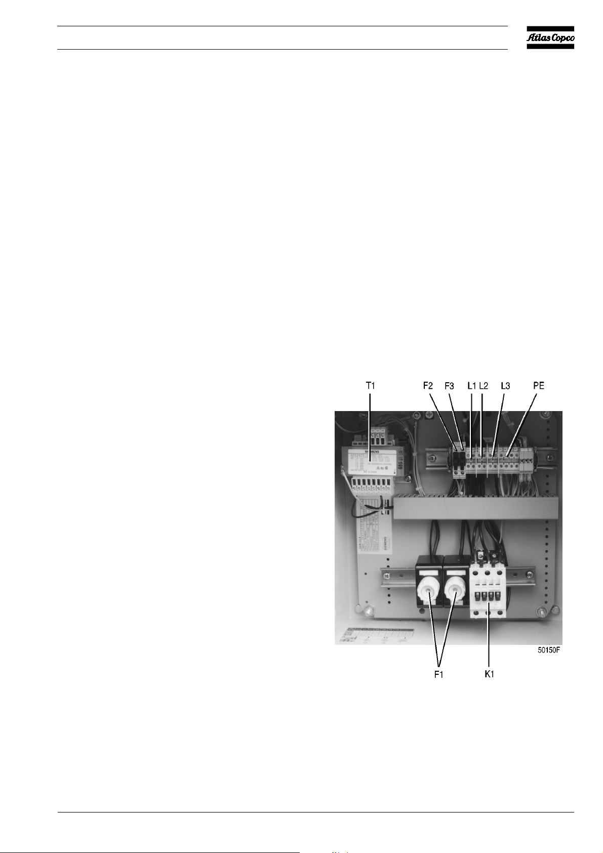
F1. Fuses, fan motor
F2/F3. Fuse, secondary side (24 V) of transformer
K1. Motor contactor, refrigerant compressor
L1/3. Terminal, mains
PE. Earth terminal
T1. T ransformer
Fig. 3. Electric cubicle (typical example)
5
Oil-free Air Division Instruction book
Fig. 4a. Side view of FD950
On air-cooled dryers, fan control switch (S3-Fig. 4b) will start
fan motor (M2-Figs. 4) as soon as the condenser pressure
reaches the upper set point of the switch and will stop the fan
motor when the condenser pressure decreases to its lower set
point.
High pressure shut-down switch (S2-Fig. 4b) stops the
compressor motor when the pressure in the refrigerant circuit
reaches the upper set point of the switch. The compressor motor
will automatically restart when the pressure drops to the lower
set point.
The motors have a built-in thermic protection. If the compressor
motor stops without apparent reason, it will most probably be
the thermic protection which has tripped. In such case, the
compressor will restart when the motor windings have cooled
down, which may take up to 2 hours.
An electronic thermostat with display and alarm functions is
installed on the instrument panel (Fig. 10). Display (3-Fig. 11)
shows the pressure dewpoint temperature. The set point value,
i.e. the pressure dewpoint temperature at which the alarm
indicator lamp (H3-Fig. 10) lights up, can be checked by
pressing key (5-Fig. 11); the value will blink for 5 seconds on
the display. The differential value ( ∆t), i.e. the temperature
difference between alarm on and alarm off, can be checked by
pressing key (4-Fig. 11); the value will blink on the display for
approx. 5 seconds.
Altering the set point value (indicated "L1"):
- Press key (5); the current value blinks on the display.
- Press the up (1) or down (2) key until the desired value is
reached.
- To store the new value, press key (5) or wait a few seconds.
6
2920 1371 00
Instruction book Oil-free Air Division
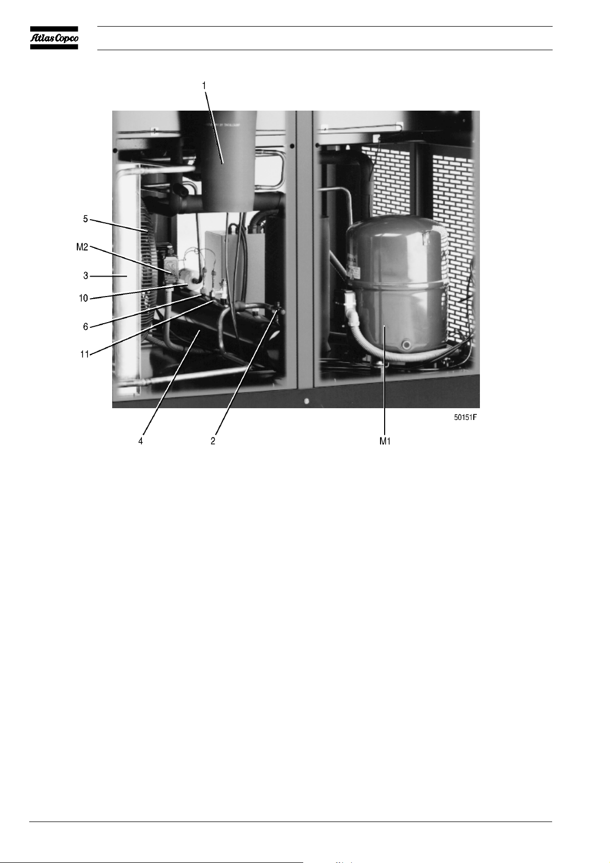
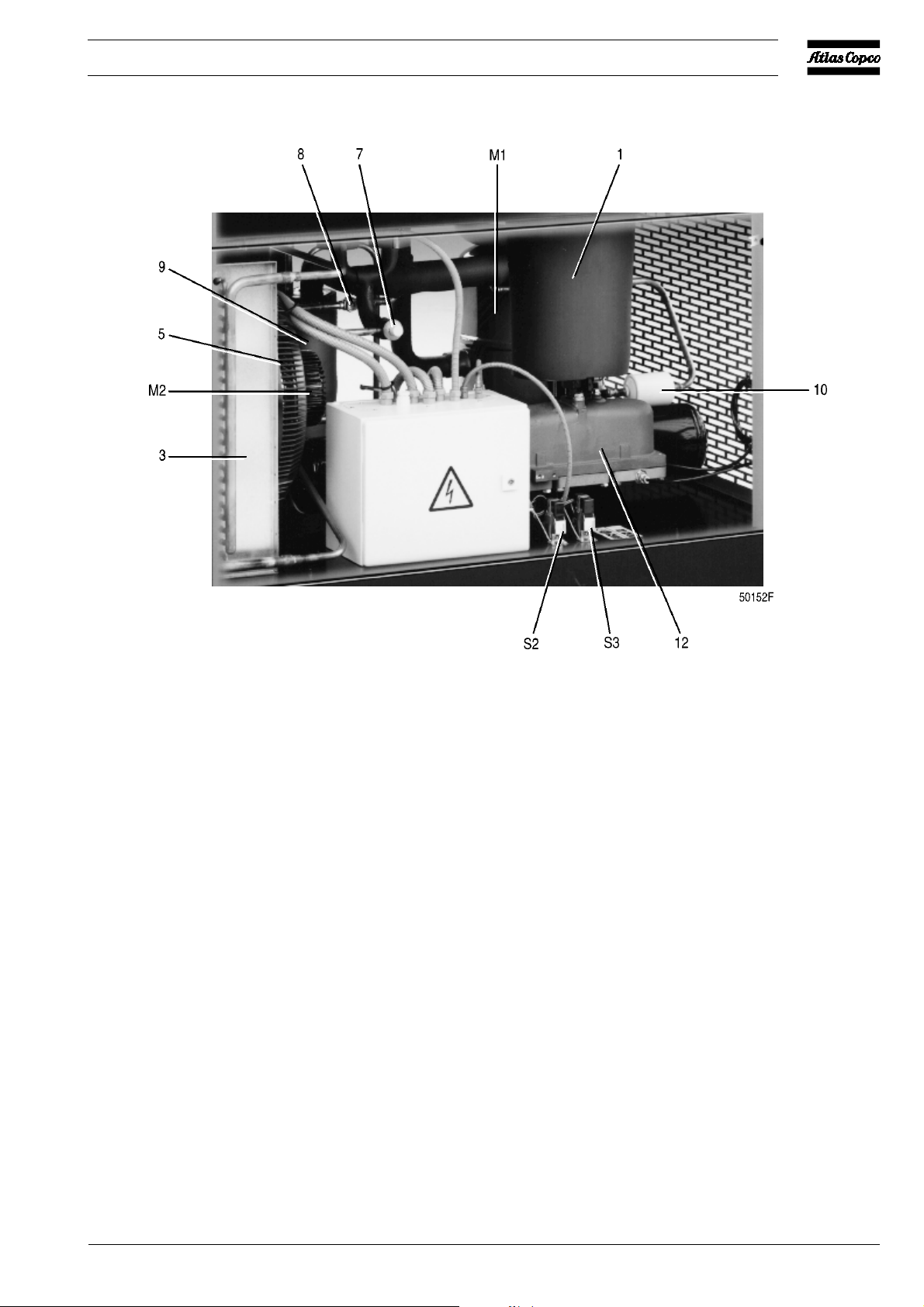
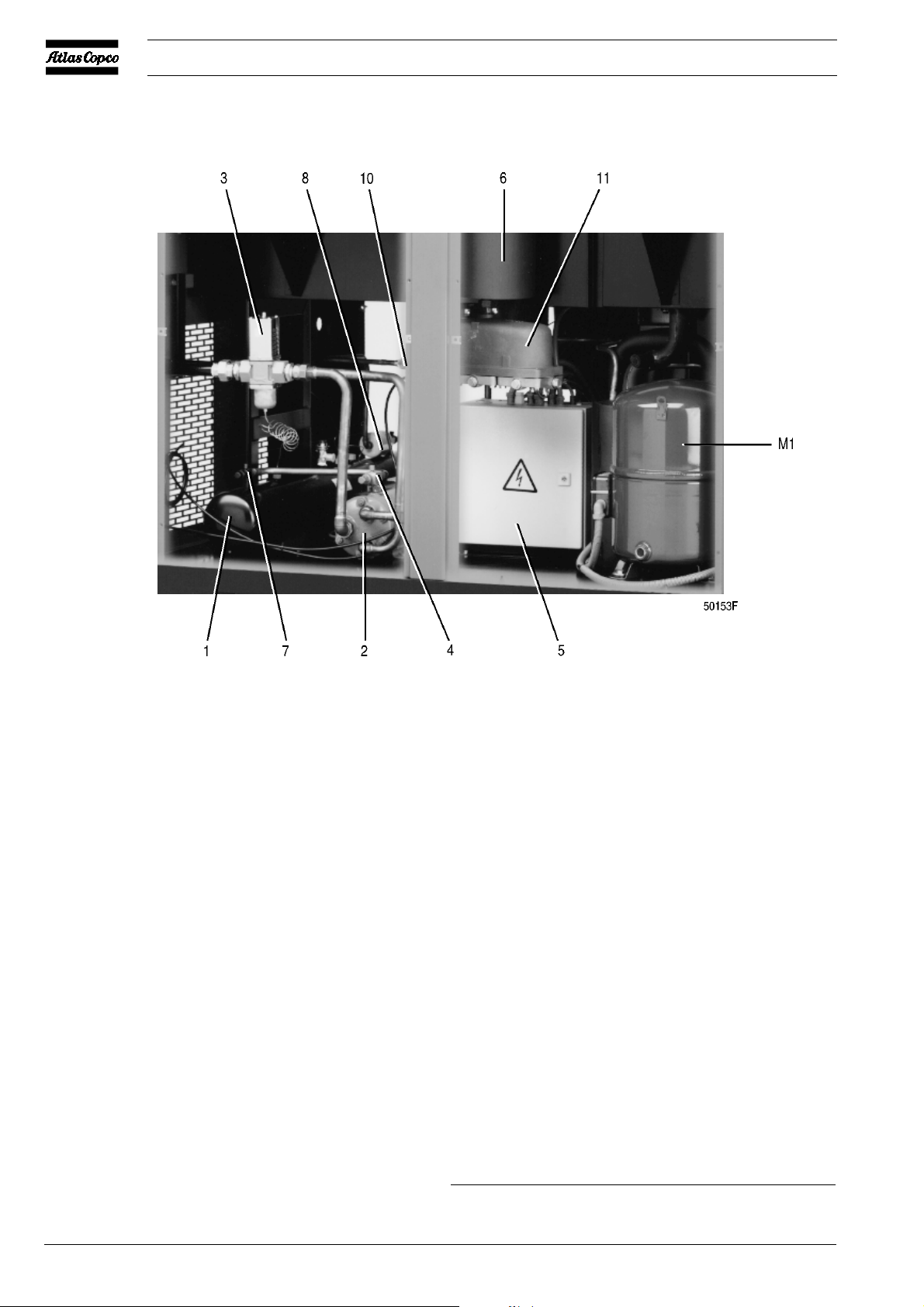
M1. Refrigerant compressor/motor
M2. Condenser cooling fan/motor
S2. High pressure shut-down switch
S3. Fan control switch
1. Condensate trap with automatic
discharge
Fig. 4b. Side view of FD700
2. Refrigerant shut-off valve
3. Condenser
4. Liquid refrigerant receiver
5. Fan
6. Sensor, high pressure shut-down
switch
7. Refrigerant expansion valve
8. Sight-glass with moisture indicator
9. Liquid separator
10. Refrigerant dryer
11. Sensor, fan control switch
12. Float valve
2920 1371 00
Figs. 4. Side views of air-cooled FD units
7
Oil-free Air Division Instruction book
Fig. 5a. Side view of FD1600
Altering the differential value (indicated "HY1"):
- Press key (4); the current value blinks on the display.
- Press the up (1) or down (2) key until the desired value is
reached.
- Press key (5) or wait a few seconds to store the new value.
If the temperature increases above the preset value, alarm
indicator lamp (H3-Fig. 10) will light up.
An automatic interval drain 1) may be connected between
condensate trap (4-Fig. 2) and manual drain valve (6-Fig. 2) to
flush the trap regularly. The interval time and opening time
can be adjusted.
1) Optional equipment.
8
2920 1371 00
 Loading...