

Atlas Copco ga37, GA18WVSD, GA30WVSD, GA37WVSD, GA45WVSD User Manual
...
User manual
2920 1456 03 1
Atlas Copco Stationary Air Compressors
GA18, -30, -37, -45, -50, -55, -75, -90 (W) VSD
User manual for Elektronikon® II regulator
1. This manual must be used together with the instruction books for GA18 up to -90 (W) VSD
compressors.
2. From following serial numbers onwards:
- GA18-30 VSD: AII 297 500
- GA37-55 VSD: AII 355 000
- GA75-90 VSD: AII 494 500
Copyright 2003, Atlas Copco Airpower n.v., Antwerp, Belgium.
Any unauthorized use or copying of the contents or any part thereof is prohibited. This applies in
particular to trademarks, model denominations, part numbers and drawings.
This instruction book meets the requirements for instructions specified by the machinery directive
98/37/EC and is valid for CE as well as non-CE labelled machines.
No. 2920 1456 03
(Replaces No. 2920 1456 02)
Registration code: APC G18-30 VSD/2002 / 38 / 977
APC G37-55 VSD/2003 / 38 / 975
APC G75-90 VSD/2000 / 38 / 987
2003-07 www.atlascopco.com

User manual
2920 1456 03 2
Contents Page
1 General description............................................................................................................................ 3
1.1 Controlling the compressor............................................................................................................ 3
1.2 Protecting the compressor............................................................................................................. 4
1.2.1 Shut-down and fan motor overload......................................................................................... 4
1.2.2 Shut-down warning.................................................................................................................. 4
1.2.3 Warning ................................................................................................................................... 4
1.3 Service warning ............................................................................................................................. 4
1.4 Automatic restart after voltage failure ............................................................................................ 4
2 Control panel (Fig. 2.1)....................................................................................................................... 5
3 Display - keys...................................................................................................................................... 6
3.1 Display (12-Fig. 2.1)....................................................................................................................... 6
3.2 Scroll keys (1-Fig. 2.1)................................................................................................................... 6
3.3 Tabulator key (2-Fig. 2.1) .............................................................................................................. 7
3.4 Function keys (3-Fig. 2.1) .............................................................................................................. 7
4 Menu-driven control programs ......................................................................................................... 7
4.1 Function of control programs ......................................................................................................... 9
4.2 Main screen ................................................................................................................................... 9
4.3 Calling up other menus................................................................................................................ 10
5 Quick look at actual compressor status ........................................................................................10
6 Status data menu.............................................................................................................................. 11
6.1 No message exists....................................................................................................................... 11
6.2 A shut-down message exists ....................................................................................................... 11
6.3 A shut-down warning message exists ......................................................................................... 12
6.4 A service warning message exists............................................................................................... 13
6.5 A warning message exists ........................................................................................................... 14
7 Measured data menu........................................................................................................................ 14
8 Counters menu ................................................................................................................................. 14
9 Test menu.......................................................................................................................................... 15
10 Modify params – modifying compr./motor settings.................................................................... 16
11 Modifying parameters .................................................................................................................... 17
12 Modifying protection settings ....................................................................................................... 18
13 Modifying service plans................................................................................................................. 20
14 Programming Clock function ........................................................................................................ 22
14.1 Programming start/stop/pressure band commands................................................................... 22
14.2 To activate/deactivate the timer................................................................................................. 24
14.3 To modify a command ............................................................................................................... 25
14.4 To add a command.................................................................................................................... 26
14.5 To delete a command ................................................................................................................ 27
15 Configuration menu ....................................................................................................................... 28
16 Service menu .................................................................................................................................. 30
17 Saved data menu ............................................................................................................................ 32
18 Programmable settings.................................................................................................................. 33
18.1 Compr./motor ............................................................................................................................. 33
18.2 Parameters ................................................................................................................................ 33
18.3 Protections ................................................................................................................................. 34
18.4 Service plan ............................................................................................................................... 34

User manual
2920 1456 03 3
1 General description
The electronic regulator automatically controls the compressor, i.e.:
- matching the compressor output to the air consumption
- stopping the compressor whenever necessary
- restarting the compressor when required
In order to control the compressor and to read and modify programmable parameters, the regulator
has a control panel provided with:
- LEDs indicating the status of the compressor
- a display indicating the operating conditions, a service need or a fault
- keys to control the compressor and to have access to the data collected by the regulator
- buttons to manually start and stop the compressor
- an emergency stop button or isolator switch
In general, the regulator has following functions:
- controlling the compressor
- protecting the compressor
- monitoring components subject to service
- automatic restart after voltage failure (made inactive)
1.1 Controlling the compressor
The regulator matches the air output to the air consumption by speed regulation of the motor.
The regulator takes into account a number of programmable settings, such as:
- net pressure setpoint
- indirect stop offset
- direct stop offset
- proportional band
- integration time
- minimum speed
- minimum stop time
- maximum speed limit
- power recovery time (if automatic restart after voltage failure is activated)
If the net pressure keeps on rising when the compressor runs at minimum speed, the regulator will
stop the compressor. The regulator restarts the motor as soon as the net pressure approaches the
net pressure setpoint.
The regulator stops the compressor whenever necessary:
- Indirect stop: i.e. the compressor runs at minimum speed and the net pressure rises to the
indirect stop level.
- Direct stop: i.e. the compressor runs at a speed in between minimum and maximum and the
net pressure rises above the direct stop setpoint.
Both settings are programmable; see section 18.

User manual
2920 1456 03 4
1.2 Protecting the compressor
1.2.1 Shut-down and fan motor overload
If the compressor element outlet temperature exceeds the programmed shut-down level, the
compressor will be stopped. This will be indicated on the control display.
The compressor will also be stopped in case of overload of the fan motor.
1.2.2 Shut-down warning
If the compressor element outlet temperature exceeds a programmed value just below the shut-down
level, this will also be indicated to warn the operator before the shut-down level is reached.
1.2.3 Warning
A warning message also appears if:
- On water-cooled compressors, the cooling water outlet temperature exceeds the warning level.
- On Full-Feature compressors, the dewpoint temperature exceeds the warning level.
1.3 Service warning
A number of service operations are grouped in plans (called Service plans A, B and C). Each Service
plan has a programmed time interval. If a time interval is exceeded, a message will appear on display
(12-Fig. 2.1) to warn the operator to carry out the service actions belonging to that plan.
1.4 Automatic restart after voltage failure
The regulator has a built-in function to automatically restart the compressor if the voltage is restored
after voltage failure. For compressors leaving the factory, this function is made inactive. If desired,
the function can be activated. Consult Atlas Copco.
Warning
If activated and provided the module was in the automatic operation mode, the compressor will
automatically restart if the supply voltage to the module is restored within a programmed time
period.
The power recovery time (the period within which the voltage must be restored to have an automatic
restart) can be set between 10 and 3600 seconds or to Infinite. If the power recovery time is set to
Infinite, the compressor will always restart after a voltage failure, no matter how long it takes to restore
the voltage. A restart delay can also be programmed, allowing e.g. two compressors to be restarted
one after the other.
User manual
2920 1456 03 5
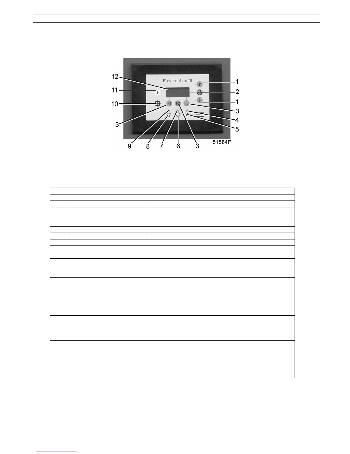
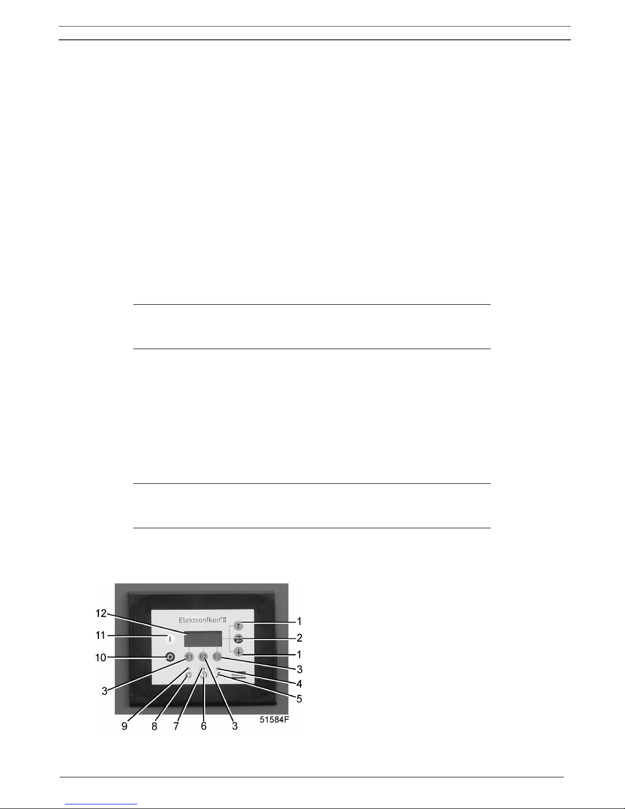
2 Control panel (Fig. 2.1)
Fig. 2.1 Control panel
LEDs/buttons/keys
Ref. Designation Function
1 Scroll keys Keys to scroll through the display.
2 Tabulator key
Key to select the parameter indicated by a horizontal
arrow.
3 Function keys Keys to control and program the compressor. See below.
4 Voltage on LED Indicates that the voltage is switched on.
5 Pictograph Voltage on.
6 Pictograph Alarm.
7 General alarm LED
Is normally out. Is alight or blinks in case of an abnormal
condition. See below.
8 Pictograph Automatic operation.
9 Automatic operation LED
Indicates that the regulator is automatically controlling the
compressor.
10 Stop button Push button to stop the compressor. LED (9) goes out.
11 Start button
Push button to start the compressor. LED (9) lights up
indicating that the regulator is operative (in automatic
operation).
12 Display
Indicates messages concerning the compressor operating
condition, a service need or a fault.
On GA37 VSD (200 V)
Isolator switch
Switch to isolate the compressor from the mains or to stop
the compressor immediately in case of emergency. The
compressor will be depressurized automatically when the
isolator switch is switched off.
On GA18/30/37/45/50/55/75/90
VSD:
Emergency stop button
Push button to stop the compressor immediately in case
of emergency. After remedying the trouble, unlock the
button by pulling it out and press the Rset key.
Note:
Previously produced compressors may be equipped with
an isolator switch
.

User manual
2920 1456 03 6
Function keys
The keys are used:
- To call up or to program settings
- To reset a motor overload, shut-down or service message, or an emergency stop
- To have access to all data collected by the regulator
The functions of the keys vary depending on the displayed menu. The actual function is abbreviated
and indicated on the bottom line of the display just above the relevant key. The most common
abbreviations are listed below.
Abbreviation Designation Function
Add
Add To add compressor start/stop commands (day/hour)
Back
Back To return to a previously shown option or menu
Canc
Cancel
To cancel a programmed setting when programming
parameters
Del
Delete To delete compressor start/stop commands
Help
Help To find the Atlas Copco internet address
Lim
Limits To show limits for a programmable setting
Main
Main To return from a menu to the main screen (Fig. 4.2)
Menu
Menu
Starting from the main screen (Fig. 4.2): to have access to
submenus
Menu
Menu Starting from a submenu, to return to the previous menu
Mod
Modify To modify programmable settings
Prog
Program To program modified settings
Rset
Reset To reset a timer or message
Rtrn
Return To return to a previously shown menu
Xtra
Extra To find information regarding the installed modules
3 Display - keys
3.1 Display (12-Fig. 2.1)
The display has four lines of 16 characters. A typical display is shown in Fig. 4.2. It indicates:
1. On the first three lines:
- the name of the sensor of which the actual reading is displayed
- the unit of measurement and actual reading of the sensor
- messages regarding the compressor operating condition (compressor off, etc.), a service need
(e.g. for the oil filter and air filter) or a fault (e.g. shut-down)
2. On the fourth line, just above the three function keys (F1/F2/F3), the actual functions of these
keys.
3.2 Scroll keys (1-Fig. 2.1)
These keys, labelled with vertical arrows, allow to scroll through the display.
As long as a downward pointing arrow is shown at the utmost right position of the display, the key (1)
with the same symbol can be used to see the next item.
As long as an upward pointing arrow is shown at the utmost right position of the display, the key (1)
with the same symbol can be used to see the previous item.

User manual
2920 1456 03 7
3.3 Tabulator key (2-Fig. 2.1)
This key, labelled with two horizontal arrows, allows the operator to select the parameter indicated by
a horizontal arrow. Only the parameters followed by an arrow pointing to the right are accessible for
modifying.
3.4 Function keys (3-Fig. 2.1)
The keys are used:
- to call up or program settings
- to reset an active fan motor overload, shut-down or service message
- to have access to all data collected by the regulator
The function keys allow to make the required selection from a menu of possibilities. The functions of
the keys vary depending on the displayed menu. The actual function is abbreviated and indicated on
the bottom line of the display just above the relevant key. Only the active and relevant functions at a
moment are shown.
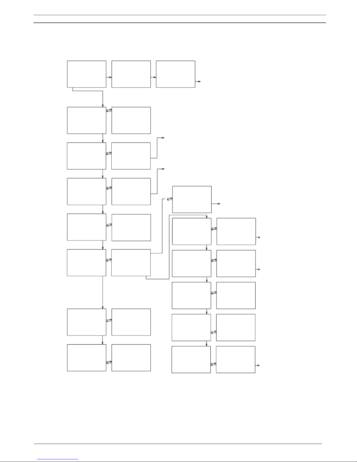
4 Menu-driven control programs
To facilitate programming and controlling the compressor, menu-driven programs are implemented in
the electronic module.
A simplified menu flow is shown in Fig. 4.1.
User manual
2920 1456 03 8
Compressor Out
bar 7.0
rpm 2500 ↓
Menu
Auto Operation
Local Control
Timer Active ↓
Main Help Xtra
Max Pressure ↑
bar 7.5
↓
Main Help Xtra
Status data →
Measured data
Counters ↓
Main
All Conditions
Are OK
Menu
Status data ↑
Measured data →
Counters ↓
Main
Compressor Out
Bar 7.0
↓
Menu
Measured data ↑
Counters →
Test ↓
Main
Counters ↑
Test →
Modify Params ↓
Main
Test ↑
Modify Params →
Service ↓
Main
Modify Params ↑
Service →
Saved data ↓
Main
Loaded hours
hrs 2107
↓
Menu
Compr Motor ↑
Parameters →
Protections ↓
Menu
Setpoint 1
bar 7.0
↓
Menu Mod
Parameters ↑
Protections →
Service Plan ↓
Menu
Compressor Out
Bar 6.8
↓
Menu
Protections ↑
Service Plan →
Clock Function ↓
Menu
Service Timer
Running hours →
hrs 130 ↓
Menu
Service Timer
Running hours →
hrs 130 ↓
Menu
Modify Params ↑
Service
Saved data →
Main
Last Shutdown 1 →
Last Shutdown 2
Last Shutdown 3 ↓
Menu
51591PEN
Service Plan ↑
Clock Function →
Configuration ↓
Menu
Clock Function
Not Activated →
Menu Mod
Time
10:54
↓
Menu Mod
-Compres Speed
-Loaded Hours
-Motor Starts
-Module Hours
-Accumulated Vol
-Compressor Out
-DP Oil Separ
-Element Outlet
-Dewpoint
-Cool Water In
-Cool Water Out
-DP Oil Separ
-Element Outlet
-Dewpoint
-Cool Water In
-Cool Water Out
-ER Water In
-ER Water Out
-Emergency Stop
-Rem Start/Stop
-Overl Fanmotor
-Condens drain
-DD filter
-PD filter
-Motor Starts
-Module Hours
-Accumulated Vol
-Setpoint 2
-Indir Stop Level
-Direct Stop Lev
-Proport Band
-Integrat Time
-Minimum speed
-Max RPM Reduct
Display test ↑
Safety valve
Regreasing ↓
Menu
-DP Oil separator
-Element outlet
-Dewpoint
-Cool Water In
-Cool Water Out
-ER Water In
-ER Water Out
-Emergency Stop
-Rem Start/Stop
-Overl Fanmotor
-Condens drain
-DD filter
-PD filter
-Date
-Date format
-Language in use
-Unit for pressure
-Unit for temperature
-Unit for vibration
-Unit fot level
-Setpoint sel
-CCM (control mode)
-Auto restart
-Password
Service Plan ↑
Clock Function
Configuration →
Menu
Compr Motor →
Parameters
Protections ↓
Menu
Fan Mot St/Day
Number
↓
Menu Mod
-Min Stop Time
-Power Rec Time
-Restart delay
-Commun Time-out
-ER Water In
-ER Water Out
-Emergency Stop
-Rem Start/Stop
-Overl Fanmotor
-Condens drain
-DD filter
-PD filter
Fig. 4.1 Menu flow

User manual
2920 1456 03 9
4.1 Function of control programs
Program/Function Description
Main screen
Shows in short the operation status of the compressor. It is the gateway
to all functions. See Fig. 4.1.
Status data
Calling up the status of the compressor protection functions:
- shut-down
- shut-down warning
- service warning
- warning
Resetting of a shut-down, motor overload and service condition.
Measured data
Calling up:
- actually measured data
- the status of a number of inputs, such as the fan motor overload
protection
Counters
Calling up the:
- loaded hours
- number of motor starts
- regulator (module) hours
- accumulated volume
Test Allows a display test.
Modify Params
Modifying the parameters for:
- compr./motor settings (e.g. setpoints)
- parameters (e.g. minimum stop time)
- protections (e.g. air temperature shut-down level)
- service plans
- clock functions (automatic compressor start/stop/pressure band
commands)
- configuration (time, date, display language, …)
Service Calling up service plans and resetting the timers.
Saved data Calling up the saved data: last shut-down, last emergency stop data
4.2 Main screen
When the voltage is switched on, the Main screen is shown automatically, showing in short the
operation status of the compressor.
Compressor out
bar 7.0
rpm 2500
↓
Menu
F1 F2 F3
Fig. 4.2 Main screen, typical example
If the function keys or arrow keys are not used for some minutes, the display will automatically return
to the Main screen.
Whenever displayed on a submenu screen, press the key Main to return to the Main screen.

User manual
2920 1456 03 10
4.3 Calling up other menus
Starting from the Main screen:
- Use the ↓ key (1) for a quick look at the actual compressor status (see section 5).
- Press the key Menu (F1); the option Status data will be followed by a horizontal arrow:
- either press the tabulator key (2) to select this menu
- or use the ↓ key (1) to scroll until the desired submenu is followed by a horizontal arrow and
then press tabulator key (2) to select this menu.
5 Quick look at actual compressor status
Procedure
1. Starting from the Main screen (see section 4.2), press the ↓ key: A screen similar to the one
below appears:
Auto Operation
Local Control
Timer Active
Main Help Xtra
↓
F1 F2 F3
Fig. 5.1 Example of an actual compressor status display
Line 1 indicates the automatic or manual operation status of the regulator:
<<Auto operation>> means that the regulator automatically adapts the operation of the
compressor, i.e. matching the compressor output to the air consumption.
Line 2 indicates whether the regulator operates in local control or remote control mode:
<<Local control>> means that the start/stop buttons on the keyboard are activated.
<<Remote control>> means that these functions are controlled remotely. Consult Atlas Copco.
Line 3 indicates whether the timer which generates time-based start and stop commands is activated
or not. See section 14.
See section 2 for the functions of keys Main, Help and Xtra.
2. Press the ↓ key to get other data (actual compressor conditions of the compressor) as shown in
Fig. 4.1.
User manual
2920 1456 03 11
6 Status data menu
The status data submenu gives information regarding the status of the compressor protection
functions (shut-down, shut-down warning, service warning and warning) and allows resetting of a shutdown, motor overload and service condition.
Procedure
Starting from the Main screen (see section 4.2):
- Press the key Menu (F1): the option Status data will be followed by a horizontal arrow.
- Press the tabulator key (2).
6.1 No message exists
In this case, LED (7) is out and the message on the display indicates that all conditions are normal
(Fig. 6.1):
All conditions
are OK
Menu
F1 F2 F3
Fig. 6.1 Example of a status data screen
6.2 A shut-down message exists
In case the compressor is shut down, LED (7) will blink.
In case of a shut-down due to too high a temperature at the compressor element outlet, a screen
similar to the one below will appear:
Element Outlet
C 122
Shd Max 120
Menu ** ** Rset
F1 F2 F3
Fig. 6.2 Example of a status data screen
 Loading...