

Atlas Copco EBL12 Product Instructions
EBL12
Printed Matter No. 9836 8184 00 Electric screwdriver
Valid from Serial No. A0609
2013-09
Product Instructions
8431 0170 11EBL12 ( 0.2-1.2 Nm)
WARNING
Read all safety warnings and instructions
Failure to follow the safety warnings and
instructions may result in electric shock, fire
and/or serious injury.
Save all warnings and instructions for
future reference

Table of content
Product information .......................................................................3
EN
Operation .....................................................................................5
EN
Service .........................................................................................9
EN
Informace o produktu ..................................................................10
CS
Provoz ........................................................................................12
CS
Servis .........................................................................................17
CS
Informations produit ....................................................................18
FR
Exploitation ................................................................................20
FR
Entretien .....................................................................................25
FR
Produktinformation .....................................................................26
DE
Bedienung ..................................................................................28
DE
EBL12Table of content
Wartung .....................................................................................33
DE
Informações do Produto ...............................................................34
PT
Operação ....................................................................................36
PT
Serviço .......................................................................................40
PT
Informazioni sul prodotto .............................................................41
IT
Funzionamento ...........................................................................43
IT
Assistenza ..................................................................................47
IT
Информация об изделии ............................................................48
RU
Эксплуатация ............................................................................50
RU
Обслуживание ...........................................................................55
RU
Información del producto .............................................................56
ES
Funcionamiento ..........................................................................58
ES
Servicio ......................................................................................63
ES
Produktinformation .....................................................................64
SV
Funktion .....................................................................................66
SV
Service .......................................................................................70
SV
Spare part list ..............................................................................71
EN
Accessories .................................................................................75
EN
2
© Atlas Copco Industrial Technique AB - 9836 8184 00

Product informationENEBL12
General information
T WARNING
• Read all safety warnings and all instructions.
Failure to follow the warnings and instructions may result in electric shock, re and/or serious injury.
• Save all warnings and instructions for future reference.
T WARNING
Special precautions for STR and ETT tools.
• Avoid using tightening strategies in applications outside their limitations.
• Major changes in joint characteristics will affect the operator reaction force.
• Consider that a joint failure or a tool error can cause sudden unexpected reaction force and possibly injure
the operator.
• Recommended value for Rundown Complete is 10% of target torque.
Safety signal words
The safety signal words Danger, Warning, Caution, and Notice have the following meanings:
DANGER
WARNING
CAUTION
DANGER indicates a hazardous situation which, if not avoided, will result in
death or serious injury.
WARNING indicates a hazardous situation which, if not avoided, could result
in death or serious injury.
CAUTION, used with the safety alert symbol, indicates a hazardous situation
which, if not avoided, could result in minor or moderate injury.
NOTICE is used to address practices not related to personal injury.NOTICE
Warranty
Contact the Atlas Copco sales representative within your area to claim a product. Warranty will only be approved
if the product has been installed, operated, lubricated and overhauled according to the Product Instructions.
Warranty will not be approved if it should be detected that the electric motor has been opened.
Please also see the delivery conditions applied by the local Atlas Copco company.
ServAid
ServAid is a utility for providing updated product information concerning:
- Safety instructions
- Installation, Operation and Service instructions
- Exploded views
ServAid facilitates the ordering process of spare parts, service tools and accessories for the product of your
choice. It is continuously updated with information of new and redesigned products.
You can use ServAid to present content in a specic language, provided translations are available, and to
display information about obsolete products. ServAid offers an advanced search functionality of our entire
product range.
ServAid is available on DVD and on the web:
http://servaidweb.atlascopco.com
For further information contact your Atlas Copco sales representative or e-mail us at:
servaid.support@se.atlascopco.com
Overview
Statement of use
This product is designed for installing and removing threaded fasteners in wood, metal or plastic.
No other use permitted. For professional use only.
© Atlas Copco Industrial Technique AB - 9836 8184 00
3

If the tool is equipped with a reaction bar
The reaction bar is designed for absorbing the reaction torque of assembly power tools.
No other use is permitted. For professional use only.
Technical data
8431017011Ordering No
EBL12Model
1/4" HexBit drive
M2-3Screw capacity
StraightModel type
ClutchShut-off system
N/A dB(A)Sound power
<70 dB(A)Sound pressure
ISO15744Sound standard
N/A dB(A)Sound uncertainty
910 r/minSpeed range
0.2-1.2 NmTorque range
1.8-10.6 in lbTorque range
30 V d.c.Motor voltage
70 WMotor power
ISO28927-2Vibration standard
N/A m/s²Vibration uncertainty
<2.5 m/s²Vibration value
0.5 kgWeight
1.1 lbWeight
EBL12ENProduct information
Service intervals
Service recommendations
Overhaul and preventive maintenance is recommended at regular intervals. If the machine is not working
properly, it should immediately be taken out of operation for inspection. At the overhauls, all parts should be
cleaned accurately and defective or worn parts should be replaced.
4
© Atlas Copco Industrial Technique AB - 9836 8184 00

OperationENEBL12
Ergonomics
Ergonomic guidelines
1) Take frequent breaks and change work positions frequently.
2) Adapt the workstation area to your needs and the work task.
• Adjust for convenient reach range by determining where parts or tools should be located to avoid static
load.
• Use workstation equipment such as tables and chairs appropriate for the work task.
3) Avoid work positions above shoulder level or with static holding during assembly operations.
• When working above shoulder level, reduce the load on the static muscles by reducing the weight of the
tool, using for example torque arms, hose reels or weight balancers. You can also reduce the load on the
static muscles by holding the tool close to the body.
• Make sure to take frequent breaks.
• Avoid extreme arm or wrist postures, particularly for operations requiring a degree of force.
4) Adjust for convenient eld of vision by minimizing movement of the eyes and head during the work task.
5) Use the appropriate lighting for the work task.
6) Select the appropriate tool for the work task.
7) Use ear protection equipment in noisy environments.
8) Use high-quality inserted tools or consumables to minimize exposure to excessive levels of vibrations.
9) Minimize exposure to reaction forces.
• When cutting:
A cut-off wheel can get stuck if the wheel is either bent or if it is not guided properly. Make sure to use
correct anges for cut-off wheels and avoid bending the wheel during cut-off operation.
• When drilling:
The drill might stall when the drill bit breaks through. Makes sure you use support handles if the stall
torque is too high. The safety standard ISO11148 part 3 recommends to use something to absorb the reaction
torque above 10 Nm for pistol grip tools and 4 Nm for straight tools.
• When using direct driven screw or nutrunners:
Reaction forces depend on tool setting and joint characteristics. The ability to bear reaction forces depends
on the operator’s strength and posture. Adapt the torque setting to the operator's strength and posture and
use a torque arm or reaction bar if the torque is too high.
10) Use dust extraction system or mouth protection mask in dusty environments.
Configuration
Tightening torque
For accurate operation and safety, the tightening torque of the screwdriver must be adjusted correctly in relation
to the screw joint. Check the torque specication for the actual joint.
The torque is set by adjusting the clutch spring with the torque key, supplied together with the screwdriver.
Tighten one screw until the clutch releases and the screwdriver stops. If needed, adjust the torque settings.
Verification of tightening torque
Atlas Copco Torque Analyser, ACTA 4000, plus an appropriately-sized in-line transducer, IRTT together with
the available test joints are recommended equipment.
Torque range of the clutch springs :
A Each clutch spring gives a certain torque range. Don’t adjust the torque over the maximum recom-
mendation as that might result in improper function and faster wear of the clutch.
© Atlas Copco Industrial Technique AB - 9836 8184 00
5
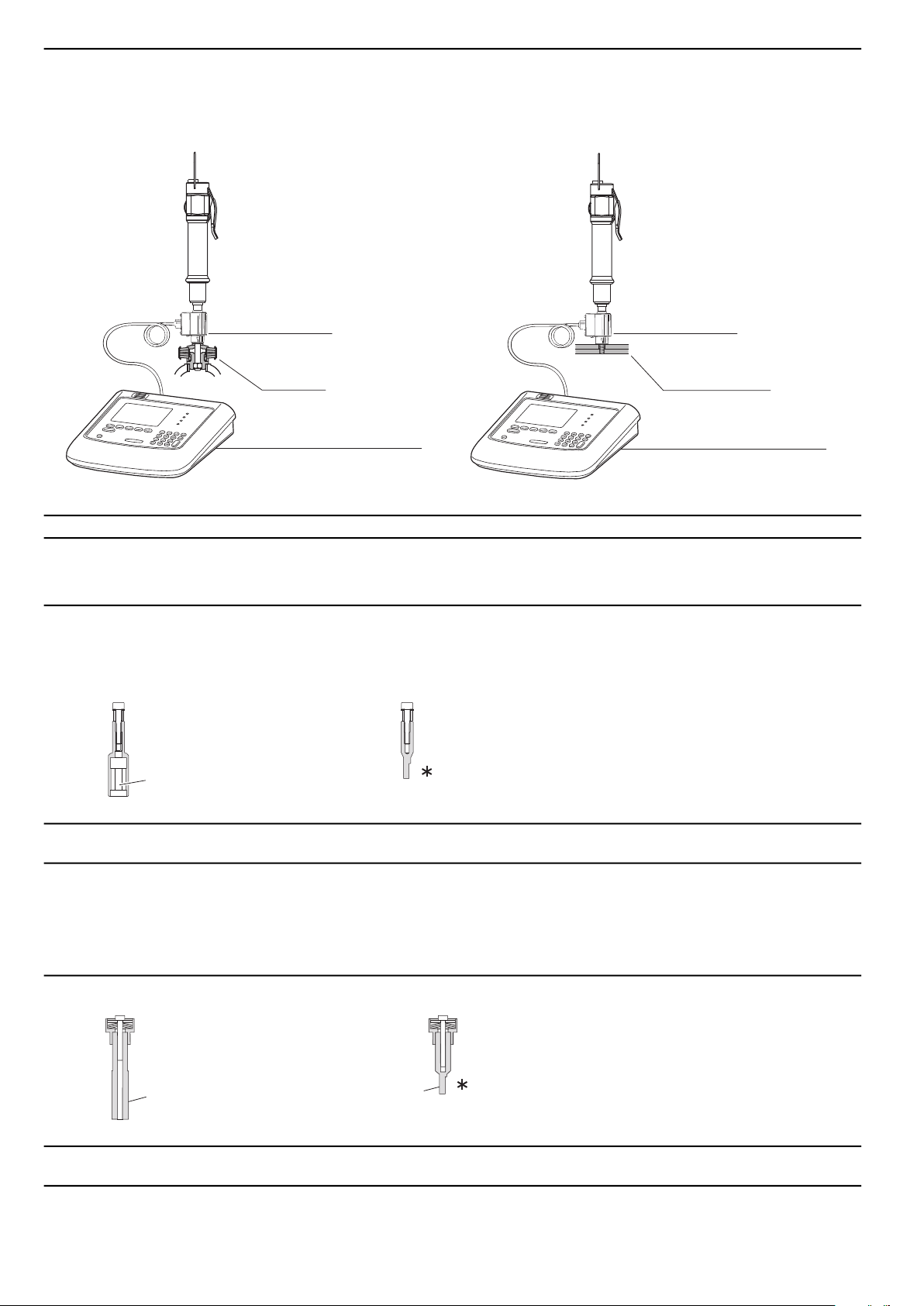
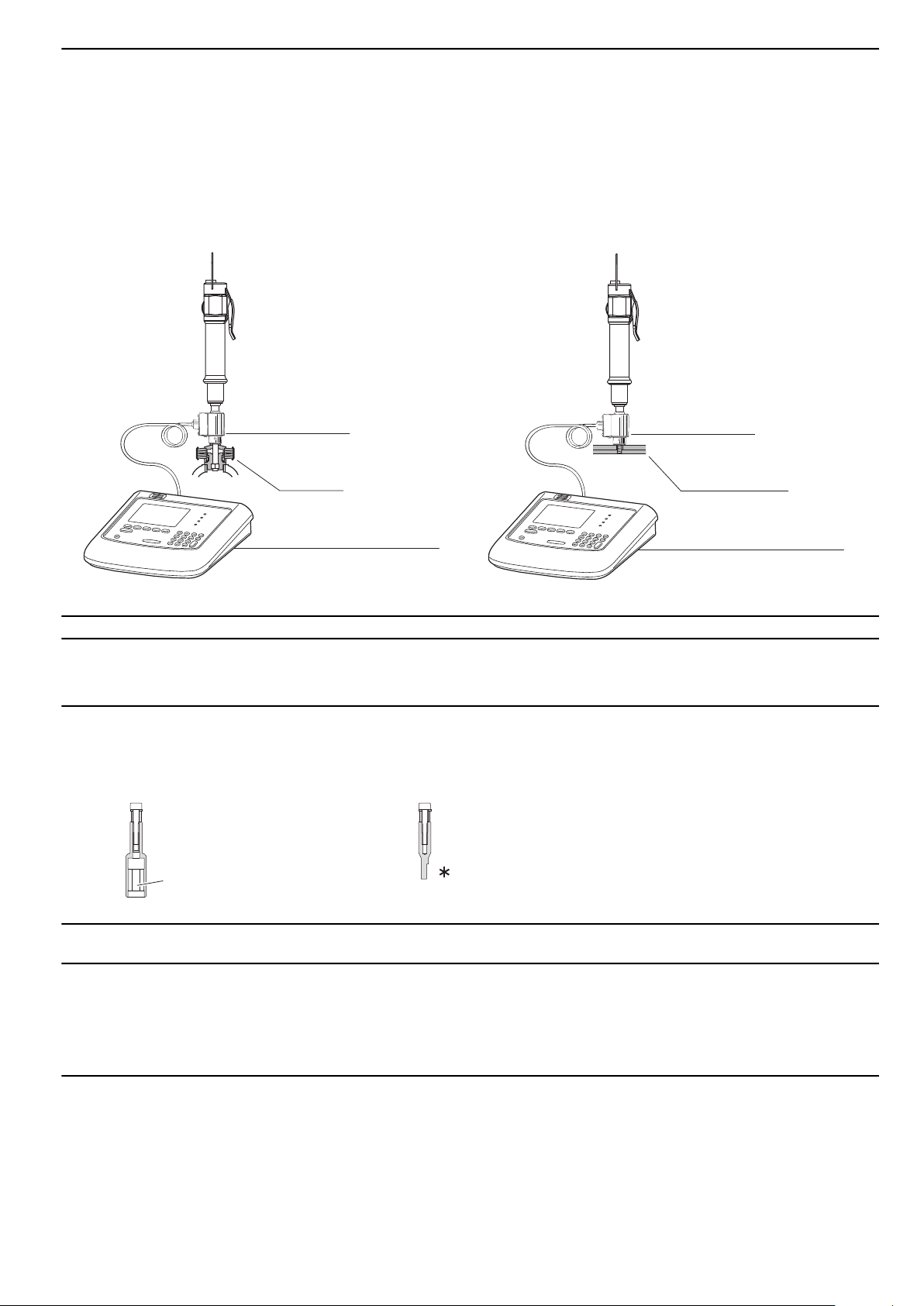
Testing of tightening torque
In the workshop At the assembly line
Yo u r actual joint
Te st joint
To rque and angle testing
instrument, ACTA 4000
To rque transducer
To rque transducer
To rque and angle testing
instrument, ACTA 4000
s011990
s009510
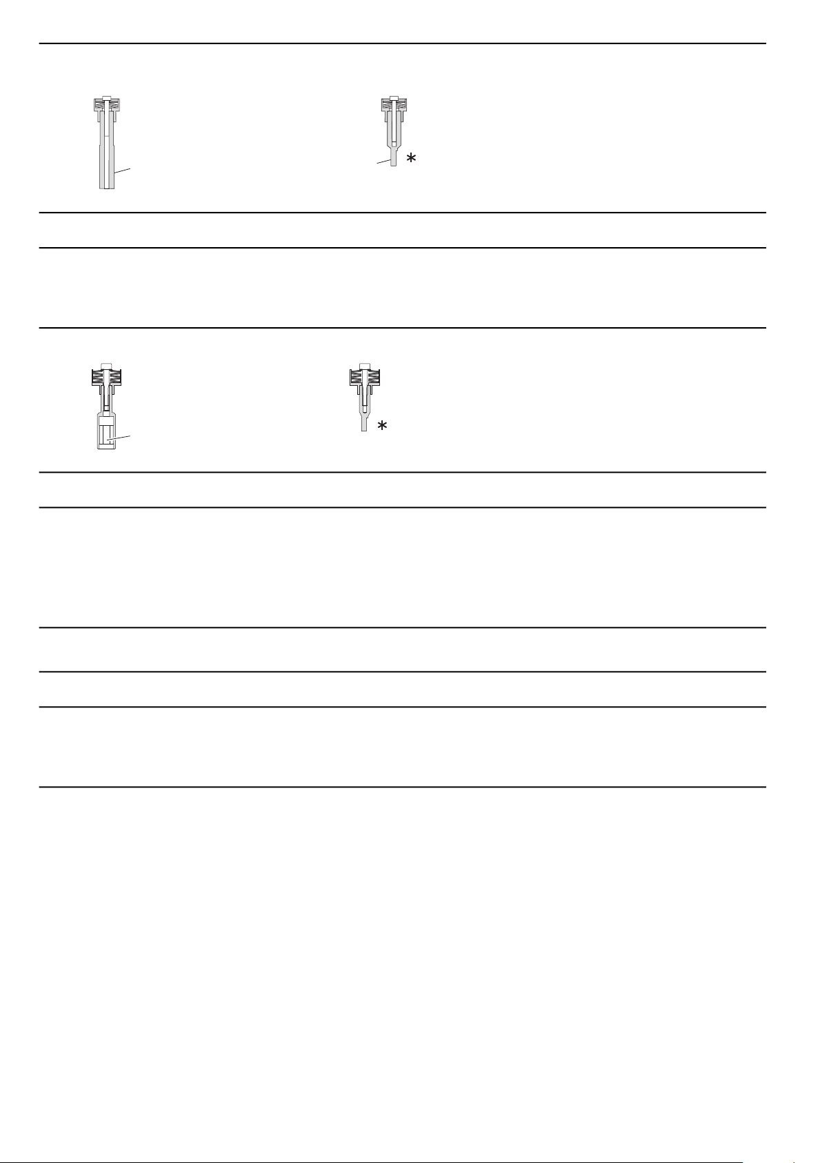
1/4" female hex connection
s009120
1/4" male hex connection
Ø 3mm
Torque and angle testing instrument
EBL12ENOperation
Ordering No.NBModel
8092 1177 20See our main catalogue or separate leafletACTA 4000 – Basic
8092 1177 30See our main catalogue or separate leafletACTA 4000 – QC
8092 1177 40See our main catalogue or separate leafletACTA 4000 – AA
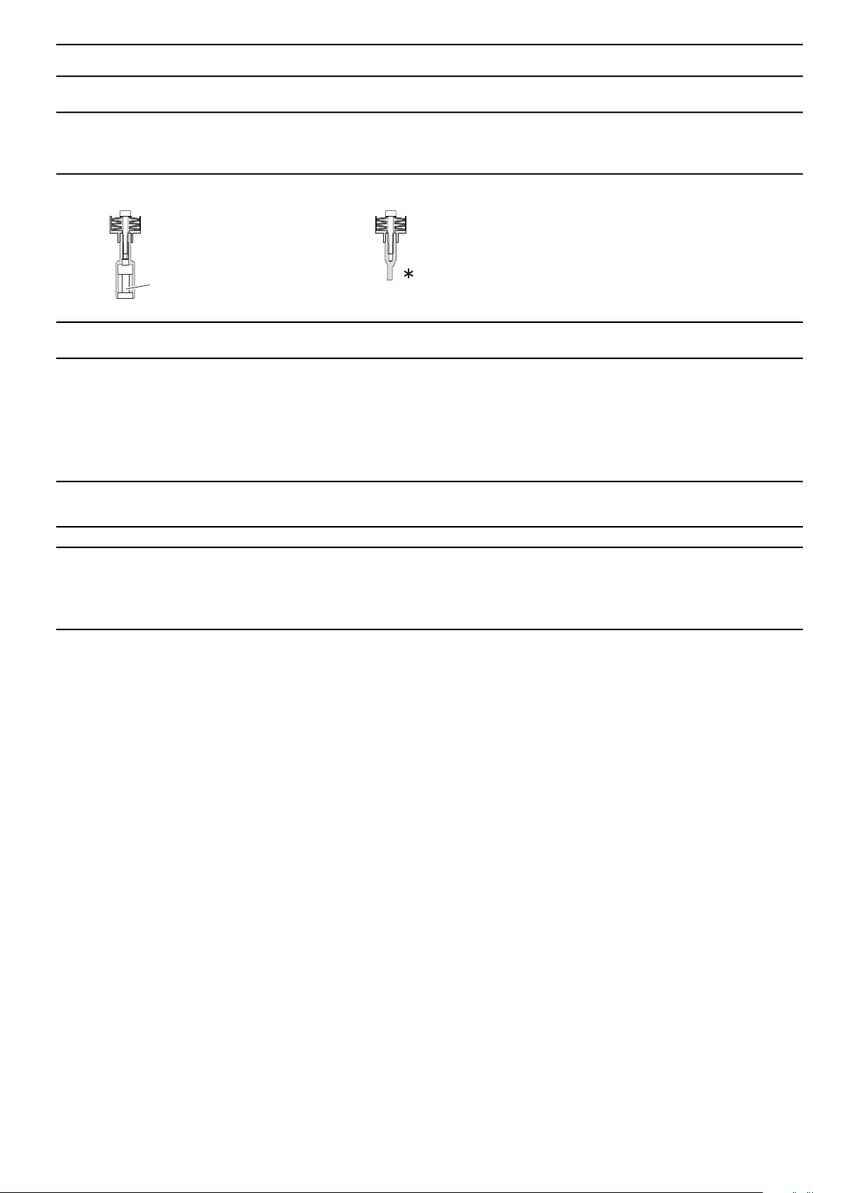
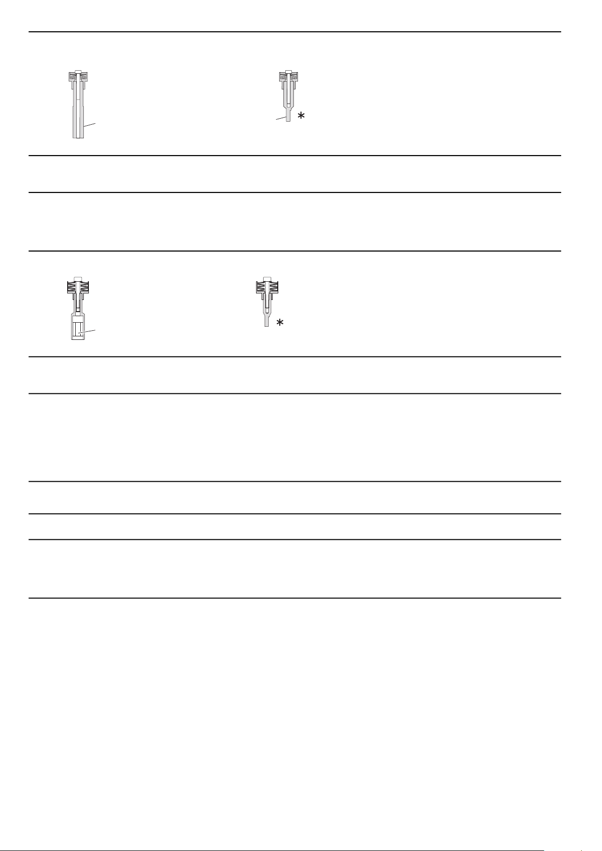
Testjoint and Transducer
Select testjoint and transducers according to minimum and maximum torque of your tool
Test joints - Hard joints
Torque range
(Nm)
Test joint
Ordering No.
Spare screw
Ordering No.Screw qualityScrew size
buy locally12.9M2x164145 0958 860.05 - 0.25
buy locally12.9M3x304145 0958 870.25 - 0.6
0211 1181 0012.9M4x504145 0958 800.5 - 1.5
0211 1177 0012.9M4x304145 0958 811.5 - 3.0
0211 1256 0012.9M6x604145 0958 823.0 - 6.0
100° joints
Torque range
(Nm)
6
Test joint
Ordering No.
© Atlas Copco Industrial Technique AB - 9836 8184 00
Spare screw
Ordering No.Screw qualityScrew size
0211 1965 4512.9M2x164145 0958 720.04 - 0.1
s009520
1/4" female hex connection
OperationENEBL12
Torque range
(Nm)
Test joint
Ordering No.
Test joints - Soft joints
Torque range
(Nm)
Test joint
Ordering No.
Spare screw
Ordering No.Screw qualityScrew size
0211 1965 4512.9M2x164145 0958 710.04 - 0.1 *
0211 1965 4512.9M2x164145 0958 730.08 - 0.2
0211 1110 0012.9M3x204145 0958 740.2 - 0.6
Spare screw
Ordering No.Screw qualityScrew size
buy locally12.9M2x164145 0958 760.04 - 0.1
buy locally12.9M3x204145 0958 770.08 - 0.2
buy locally12.9M3x204145 0958 780.2 - 0.6
0211 1177 0012.9M4x304145 0959 800.6 - 2.0
0211 1251 0012.9M6x354145 0959 811.5 - 4.0
0211 1251 0012.9M6x354145 0959 823.0 - 7.0
In-line torque transducers - Torque/angle models
Ordering Noft lbRated capacity NmDrive Square inchDrive Hex inchModel
8092 1130 960.81½IRTT 1A-I06
8092 1182 011.52½IRTT 2A-I06
8092 1182 0645¼IRTT 5A-I06
8092 1182 0845¼IRTT 5A-06
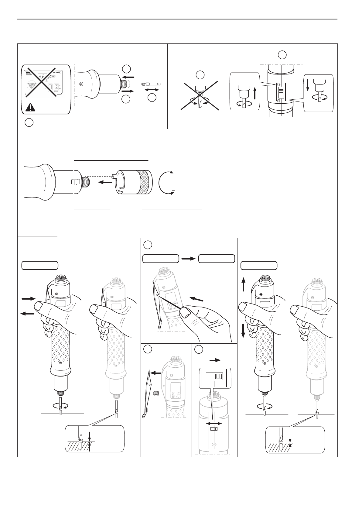
Operating instructions
Fuses
The EBL Drive and EBL RE-Drive have a built-in PTC protection. To reset disconnect the mains plug for 10
seconds.
Attaching the bit
T Make sure you disconnect the tool from the power source before replacing the tool bit, especially
when using a push start type tool. Replacing the bit while the tool is connected to a power source
may cause injury when the bit begins to rotate.
General
The screwdriver is designed to work with the EBL drive or EBL RE-Drive as power unit.
Start options
The EBL screwdriver is equipped with options for lever start and push start. With lever start the tool starts by
pulling the black lever on the machine. With push start the tool starts by pushing the bit towards the screw and
work piece. Start mode is easily recongured by changing the switch position under the lever of the tool.
© Atlas Copco Industrial Technique AB - 9836 8184 00
7
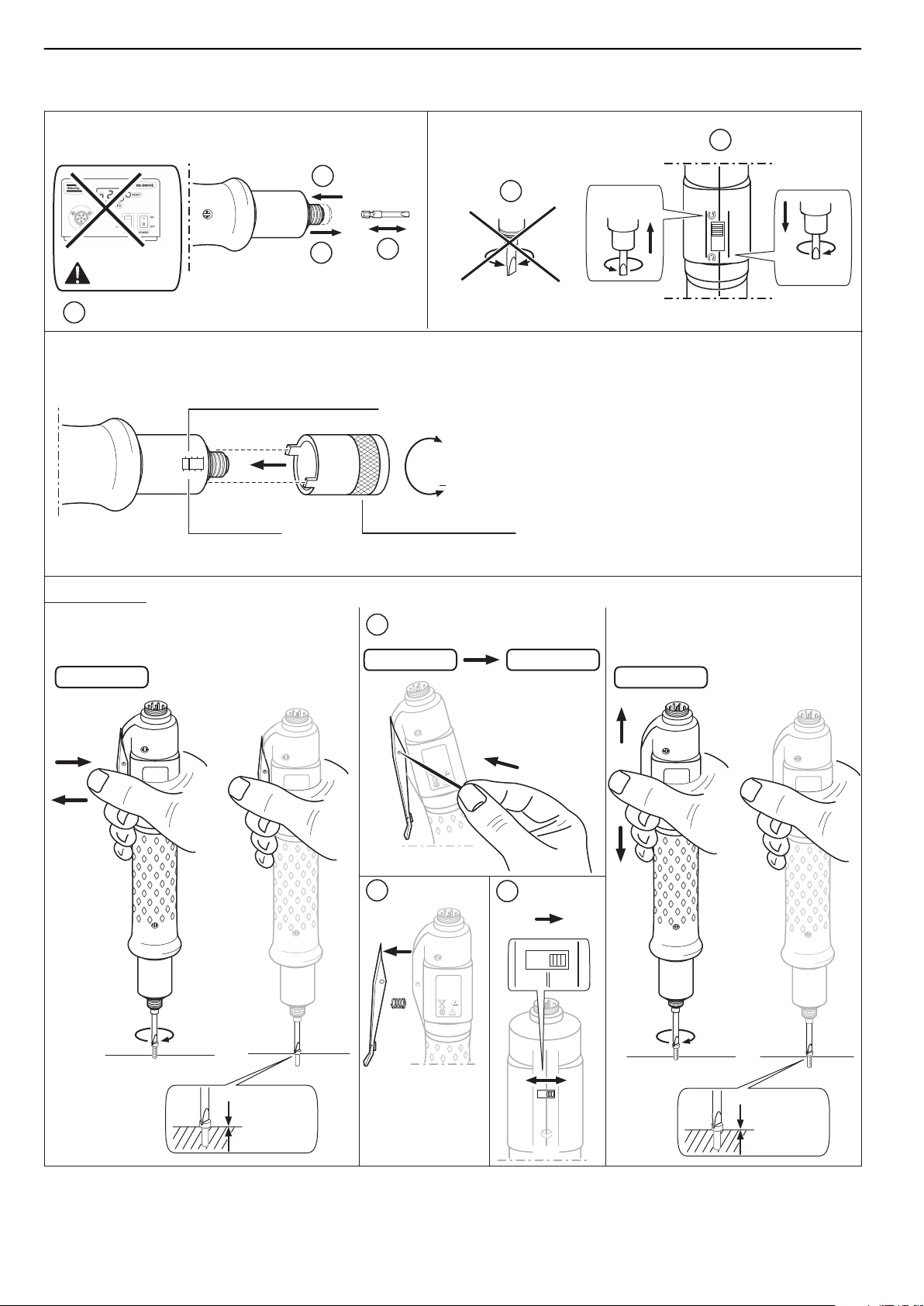
Operating procedure
Power OFF
Drive unit
ReversingChange of bit
Start options
Setting of tightening torque
2
1
+
To rque scale
Red notch = Tor que indication
To rque adjustment key
315
7
426
8
Stop
Lever start
Lever start
Start
EBL
0.03-0.3 Nm
1000 rpm
Max 30 V DC
EPA
EBL
0.03-0.3 Nm
1000 rpm
Max 30 V DC
EPA
EBL
0.03-0.3 Nm
1000 rpm
Max 30 V DC
EPA
EBL
0.03-0.3 Nm
1000 rpm
Max 30 V DC
EPA
Start
Push start
Push start
Lever Push
Lever Push
EBL
0.03-0.3 Nm
1000 rpm
Max 30 V DC
EPA
Stop
1
2
4
3
1
2
3
= Soft Stop
= Soft Stop
Stop before reversing
Forward
Reverse
Lever Push
s009710
EBL
0.03-0.3 Nm
1000 rpm
Max 30 V DC
EPA
EBL12ENOperation
8
© Atlas Copco Industrial Technique AB - 9836 8184 00
wrist strap
ESD carpet
s004120
ATTENTION
OBSERVE PRECAUTIONS
FOR HANDLING
ELECTROSTATIC
SENSITIVE
DEVICES
2002600
0.1cm
3
7mm
7mm
ServiceENEBL12
Maintenance
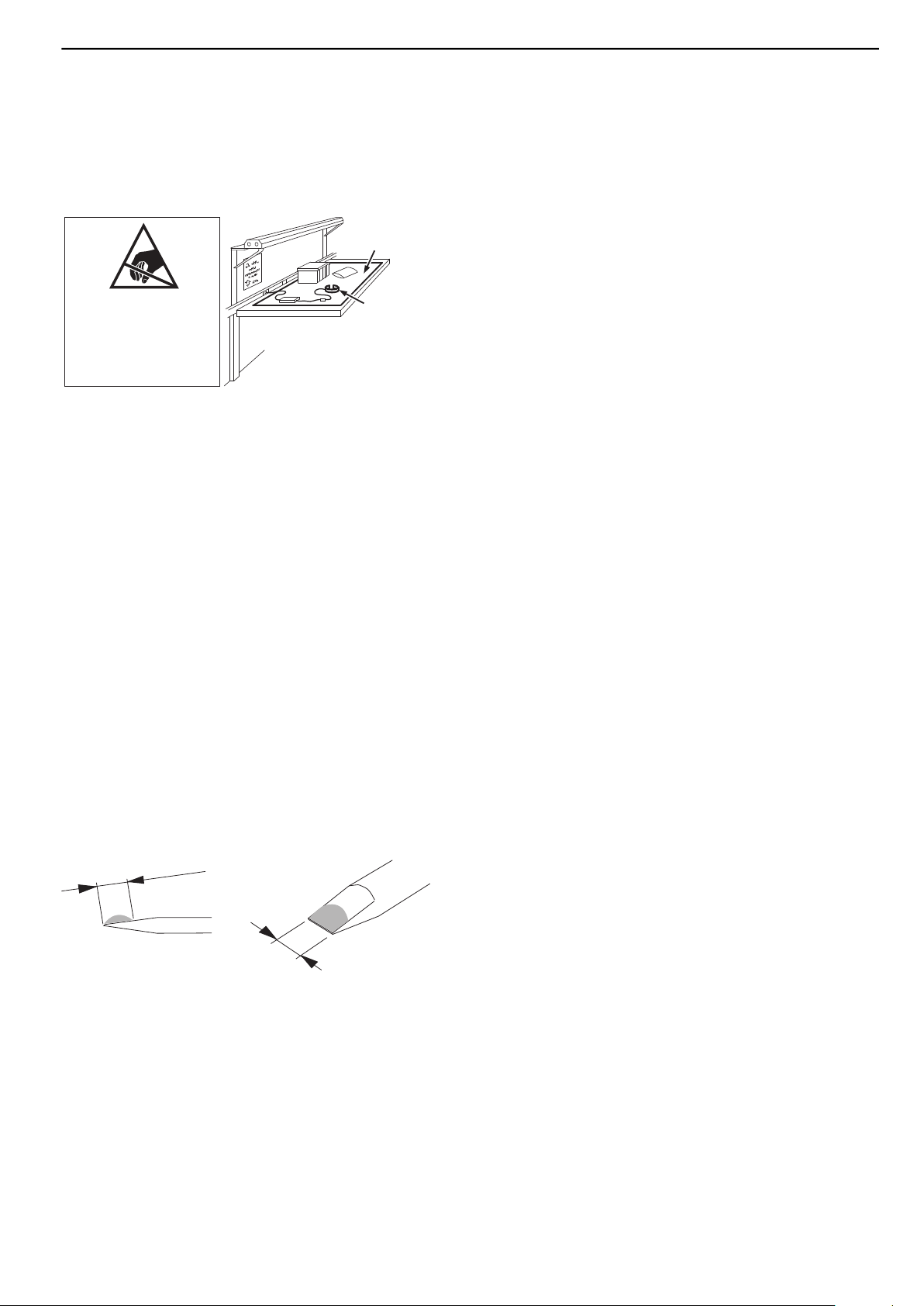
Preventing ESD problems
The components inside the tool and controller are sensitive for electrostatic discharge. To avoid future malfunction, make sure to perform service and maintenance in an ESD approved work environment. See below gure
as an example of an acceptable work station for service.
Service instructions
Overhaul and preventive maintenance is recommended at regular intervals once per year or after maximum
250.000 tightening depending on which occurs sooner. More frequent overhaul may be needed if used at high
torque, high cycle rate or long tightening times. If the machine is not working properly, it should immediately
be taken away for inspection.
At the overhauls, all parts should be cleaned accurately and defective or worn parts (i.e. O-rings) should be
replaced.
Cleaning/Inspection
Clean all parts thoroughly in white spirit or similar cleaning agent. After the cleaning, inspect all parts. Damaged
and worn parts should be replaced.
Overhaul
No regular overhaul is needed, except for complementory lubrication of gears.
Lubrication
Lubrication
The planetary gears are lubricated with grease of type Molykote Longterm 00. If needed, a complementary
lubrication (see g.) of grease could be made, maximum 0.2 cm3.
No further regular lubrication is required.
Repair
© Atlas Copco Industrial Technique AB - 9836 8184 00
9

EBL12CSInformace o produktu
Všeobecné informace
T VÝSTRAHA
• Přečtěte si veškerá bezpečnostní varování a veškeré pokyny.
Nedodržení varování a pokynů může mít za následek úraz elektrickým proudem, požár anebo vážný úraz.
• Uschovejte veškeré texty varování a pokynů i pro budoucí potřebu.
T VÝSTRAHA
Speciální bezpečnostní opatření pro nástroje STR a ETT
• Nepoužívejte strategie utahování v aplikacích, které vyžadují překročení mezních hodnot pro jejich používání.
• Velké změny charakteristik spoje ovlivní reakční sílu působící na operátora.
• Nezapomínejte, že při selhání spoje nebo poruše nástroje může vzniknout náhlá neočekávaná reakční síla,
která může operátorovi způsobit úraz.
• Doporučená hodnota pro dokončení doběhu je 10 % cílového momentu.
Výstražná upozornění
Výstražná upozornění Nebezpečí, Výstraha, Varování a Upozornění mají následující význam:
NEBEZPEČÍ
VÝSTRAHA
VAROVÁNÍ
UPOZORNĚNÍ
NEBEZPEČÍ značí nebezpečnou situaci, která, pokud se na ní nebude brát
ohled, zaviní smrt nebo vážné zranění.
VÝSTRAHA značí nebezpečnou situaci, která, pokud se na ní nebude brát
ohled, může zavinit smrt nebo vážné zranění.
VAROVÁNÍ, ve spojení s bezpečnostním výstražným symbolem, značí
nebezpečnou situaci, která, pokud se na ní nebude brát ohled, může zavinit
v některých případech zranění.
UPOZORNĚNÍ se používá k označení postupů, které nejsou spojeny s rizikem
úrazu.
Záruka
Chcete-li výrobek reklamovat, kontaktujte prodejního zástupce společnosti Atlas Copco ve vaší oblasti.Záruka
bude schválena pouze v případě, že výrobek byl nainstalován, provozován, bylo prováděno jeho mazání a byla
na něm prováděna celková údržba podle pokynů týkajících se produktu.
Reklamace nebude schválena, pokud se zjistí, že byl otevřen elektrický motor.
Viz prosím také dodací podmínky místní společnosti Atlas Copco.
ServAid
ServAid je softwarový nástroj, který poskytuje následující aktualizované informace o produktech:
– Bezpečnostní pokyny
– Pokyny týkající se instalace, provozu a údržby
– Nákresy rozebraných zařízení
ServAid usnadňuje proces objednávání náhradních dílů, servisních nástrojů a příslušenství pro vámi vybrané
produkty. Je neustále aktualizován informacemi o nových i přepracovaných produktech.
ServAid může prezentovat obsah v určitém jazyce, pokud jsou jeho překlady k dispozici, a zobrazit informace
o již neužívaných výrobcích. ServAid nabízí funkci pokročilého vyhledávání veškerého obsahu v naší nabídce.
Softwarový nástroj ServAid je k dispozici na disku DVD a na webové stránce:
http://servaidweb.atlascopco.com
Další informace si vyžádejte u svého prodejního zástupce společnosti Atlas Copco, nebo nám napište na e-
mailovou adresu:
servaid.support@se.atlascopco.com
10
© Atlas Copco Industrial Technique AB - 9836 8184 00

Informace o produktuCSEBL12
Přehled
Prohlášení o použití
Tento produkt je zkonstruován pro montáž upevňovacích prvků do dřeva, kovu nebo plastu a pro jejich demontáž
z těchto materiálů.
Žádné jiné použití není povoleno. Pouze pro profesionální použití.
Pokud je nástroj vybaven reakční tyčí
Reakční tyč je konstruována k absorbování reakčního momentu sestavy mechanického nástroje.
Žádné jiné použití není povoleno. Pouze pro profesionální použití.
Technické údaje
8431017011Objednací číslo
EBL12Model
1/4" HexUpnutí pro pracovní nástavec
M2-3Kapacita pro šrouby
StraightModelový typ
ClutchVypínací systém
N/A dB(A)Akustický výkon
<70 dB(A)Akustický tlak
ISO15744Akustický standard
N/A dB(A)Akustická nestálost
910 ot./minRozsah otáček
0.2-1.2 NmRozsah utahovacího momentu
1.8-10.6 in lbRozsah utahovacího momentu
30 V d.c.Napětí motoru
70 WVýkon motoru
ISO28927-2Standardní vibrace
N/A m/s²Nestálost vibrací
<2.5 m/s²Hodnota vibrací
0.5 kgHmotnost
1.1 lbHmotnost
Servisní intervaly
Servisní doporučení
Celkovou a preventivní údržbu je doporučeno provádět v pravidelných intervalech. Pokud stroj nepracuje
správně, je nutné jej ihned vyřadit z provozu a prohlédnout. Při provádění celkové údržby je nutné všechny díly
pečlivě očistit a vadné nebo opotřebované díly vyměnit.
© Atlas Copco Industrial Technique AB - 9836 8184 00
11

EBL12CSProvoz
Ergonomie
Pokyny pro ergonomickou práci
1) Při práci dělejte časté přestávky a často měňte polohu.
2) Přizpůsobte si pracoviště tak, aby vyhovovalo vašim potřebám a vykonávané práci.
• Zajistěte si pohodlný dosah stanovením míst, kde musí být umístěny díly nebo nástroje, aby se zabránilo
statické zátěži.
• Používejte vybavení pracoviště, jako jsou například stoly a židle, způsobem vhodným pro vykonávanou
práci.
3) Při montážních operacích se vyhýbejte pracovním polohám nad úrovní ramen nebo činnostem spojeným
s nehybným držením těla.
• Při práci v poloze nad úrovní ramen snižte zátěž nehybných svalů snížením váhy nástroje, například pomocí
momentových ramen, navíjecích bubnů nebo vyvažovacích zařízení. Snížit zátěž nehybných svalů můžete
také držením nástroje blíže u těla.
• Zajistěte časté přestávky v práci.
• Vyhýbejte se extrémním polohám paží a zápěstí, zejména u operací vyžadujících vynaložení určité síly.
4) Zajistěte si pohodlné zorné pole minimalizací pohybů očí a hlavy během práce.
5) Při práci používejte vhodné osvětlení.
6) Pro práci vyberte vhodný nástroj.
7) V hlučném prostředí používejte ochranu sluchu.
8) Používejte vysoce kvalitní nástroje nebo spotřební materiál, abyste minimalizovali vystavení se nadměrným
úrovním vibrací.
9) Minimalizujte své vystavení se účinkům reakčních sil.
• V případě řezání:
Pokud řezný je kotouč ohnutý nebo pokud není správně veden, může dojít k jeho zaseknutí. Ujistěte se,
že pro řezné kotouče používáte správné přírubové spojky, a při řezání se vyhněte ohýbání kotouče.
• V případě vrtání:
Pokud dojde ke zlomení břitu vrtáku, může se vrták zaseknout. Je-li mezní moment příliš vysoký,
nezapomeňte použít pomocné rukojeti. Bezpečnostní norma ISO11148, část 3, doporučuje použití prostředku
k absorbování reakčního momentu, pokud je vyšší než 10 Nm u nástrojů s pistolovou rukojetí a pokud je
vyšší než 4 Nm u nástrojů s přímým pouzdrem.
• Při používání nástrojů s přímým vedením šroubů nebo utahováků:
Reakční síly závisí na nastavení nástroje a charakteristikách spoje. Schopnost odolávat reakčním silám
závisí na síle a poloze operátora. Přizpůsobte nastavení momentu síle a poloze operátora a použijte
momentové rameno nebo reakční tyč, je-li moment příliš vysoký.
10) V prašném prostředí používejte systém na odsávání prachu nebo protiprachovou masku.
Konfigurace
Utahovací moment
Pro přesný provoz a bezpečnost musí být utahovací moment šroubováku nastaven přesně vzhledem k šroubovému
spoji. Zkontrolujte specikace pro dotažení daného šroubového spoje.
Utahovací moment se upravuje nastavením pružiny spojky pomocí dotahovacího klíče dodaného spolu se
šroubovákem. Dotahujte jeden šroub, dokud nedojde k uvolnění spojky a zastavení šroubováku. Pokud třeba,
upravte nastavení utahovacího momentu.
Ověření utahovacího momentu
Doporučeným vybavením je analyzátor utahovacího momentu Atlas Copco, ACTA 4000, plus snímač IRTT
příslušné velikosti spolu s příslušnými zkušebními spoji.
12
© Atlas Copco Industrial Technique AB - 9836 8184 00

In the workshop At the assembly line
Yo u r actual joint
Te st joint
To rque and angle testing
instrument, ACTA 4000
To rque transducer
To rque transducer
To rque and angle testing
instrument, ACTA 4000
s011990
s009510
1/4" female hex connection
ProvozCSEBL12
Rozsah momentu spojkových pružin:
A Každá spojková pružina poskytuje určité rozmezí momentů. Nenastavujte moment přes maximální
doporučenou hodnotu, protože by to mohlo způsobit nesprávnou funkci a rychlejší opotřebení
spojky.
Testování utahovacího momentu
Přístroj na testování momentu a úhlu
Objednací čísloNBModel
8092 1177 20Viz náš hlavní katalog nebo samostatný letákACTA 4000 – základní
8092 1177 30Viz náš hlavní katalog nebo samostatný letákACTA 4000 – QC
8092 1177 40Viz náš hlavní katalog nebo samostatný letákACTA 4000 – AA
Testovací spoj a převodník
Vyberte testovací spoj a převodník podle minimálního a maximálního momentu nástroje
Testovací spoje – tvrdé spoje
Rozsah utahovacího
momentu
(Nm)
Testovací spoj
Objednací č.
Náhradní šroub
Objednací č.Kvalita šroubuVelikost šroubu
nakupte lokálně12,9M2x164145 0958 860.05 - 0.25
nakupte lokálně12,9M3x304145 0958 870.25 - 0.6
0211 1181 0012,9M4x504145 0958 800.5 - 1.5
0211 1177 0012,9M4x304145 0958 811.5 - 3.0
0211 1256 0012,9M6x604145 0958 823.0 - 6.0
© Atlas Copco Industrial Technique AB - 9836 8184 00
13
100° spoje
s009120
1/4" male hex connection
Ø 3mm
s009520
1/4" female hex connection
Rozsah utahovacího
momentu
(Nm)
Testovací spoj
Objednací č.
Testovací spoje – měkké spoje
EBL12CSProvoz
Náhradní šroub
Objednací č.Kvalita šroubuVelikost šroubu
0211 1965 4512,9M2x164145 0958 720.04 - 0.1
0211 1965 4512,9M2x164145 0958 710.04 - 0.1 *
0211 1965 4512,9M2x164145 0958 730.08 - 0.2
0211 1110 0012,9M3x204145 0958 740.2 - 0.6
Rozsah utahovacího
momentu
(Nm)
Testovací spoj
Objednací č.
In-line převodníky momentu – momentové/úhlové modely
Model
Šestihranný pohon
palcový
palcový
Jmenovitá kapacita (Nm)Čtvercový pohon
Návodu k obsluze
Náhradní šroub
Objednací č.Kvalita šroubuVelikost šroubu
nakupte lokálně12,9M2x164145 0958 760.04 - 0.1
nakupte lokálně12,9M3x204145 0958 770.08 - 0.2
nakupte lokálně12,9M3x204145 0958 780.2 - 0.6
0211 1177 0012,9M4x304145 0959 800.6 - 2.0
0211 1251 0012,9M6x354145 0959 811.5 - 4.0
0211 1251 0012,9M6x354145 0959 823.0 - 7.0
Objednací číslo
(ft lb)
8092 1130 960,81½IRTT 1A-I06
8092 1182 011.52½IRTT 2A-I06
8092 1182 0645¼IRTT 5A-I06
8092 1182 0845¼IRTT 5A-06
Pojistky
Pohony EBL Drive a EBL RE-Drive mají vestavěnou ochranu PTC. Reset provedete odpojením síťové zástrčky
na dobu 10 vteřin.
Připojení bitu
T Před výměnou bitu se ujistěte, že šroubovák je odpojen od zdroje napájení, především pokud
používáte šroubovák s aktivací tlakem. Výměna bitu ve chvíli, kdy je šroubovák připojen ke zdroji
napájení, může způsobit zranění, pokud se bit roztočí.
14
© Atlas Copco Industrial Technique AB - 9836 8184 00

ProvozCSEBL12
Obecně
Šroubovák je určen pouze pro užití s pohony EBL Drive nebo EBL RE-Drive.
Možnosti aktivace
Šroubovák EBL nabízí možnost aktivace pákou nebo stiskem. V případě aktivace pákou lze nástroj spustit
zatažením za černou páku na stroji. Je-li zvolena aktivace stiskem, nástroj lze spustit přitlačením bitu na šroub
a předmět montáže. Konguraci aktivačního režimu je možné snadno upravit změnou pozice přepínače pod
pákou nástroje.
© Atlas Copco Industrial Technique AB - 9836 8184 00
15
Provozní postup
Power OFF
Drive unit
ReversingChange of bit
Start options
Setting of tightening torque
2
1
+
To rque scale
Red notch = Tor que indication
To rque adjustment key
315
7
426
8
Stop
Lever start
Lever start
Start
EBL
0.03-0.3 Nm
1000 rpm
Max 30 V DC
EPA
EBL
0.03-0.3 Nm
1000 rpm
Max 30 V DC
EPA
EBL
0.03-0.3 Nm
1000 rpm
Max 30 V DC
EPA
EBL
0.03-0.3 Nm
1000 rpm
Max 30 V DC
EPA
Start
Push start
Push start
Lever Push
Lever Push
EBL
0.03-0.3 Nm
1000 rpm
Max 30 V DC
EPA
Stop
1
2
4
3
1
2
3
= Soft Stop
= Soft Stop
Stop before reversing
Forward
Reverse
Lever Push
s009710
EBL
0.03-0.3 Nm
1000 rpm
Max 30 V DC
EPA
EBL12CSProvoz
16
© Atlas Copco Industrial Technique AB - 9836 8184 00

wrist strap
ESD carpet
s004120
ATTENTION
OBSERVE PRECAUTIONS
FOR HANDLING
ELECTROSTATIC
SENSITIVE
DEVICES
2002600
0.1cm
3
7mm
7mm
ServisCSEBL12
Údržba
Předcházení problémům ESD
Vnitřní součásti nástroje a řídicí jednotka jsou citlivé na elektrostatické výboje. Aby si nástroj zachoval
dlouhodobou funkčnost, provádějte servis a údržbu v pracovním prostředí schváleným ESD. Obrázek níže
znázorňuje příklad přijatelného pracoviště pro provádění servisních prací.
Pokyny k servisu
Provedení důkladné prohlídky a preventivní údržby se doporučuje v pravidelných intervalech jednou za rok,
nebo po maximálně 250 000 utaženích, podle toho, co nastane dříve. Častější provádění důkladné prohlídky
může být nutné při používání vysokého momentu, vysoké rychlosti cyklu a dlouhých časech utahování. Pokud
stroj nepracuje správně, je nutné jej ihned vyřadit z provozu a prohlédnout.
Při důkladných prohlídkách je nutné všechny díly pečlivě očistit a vadné nebo opotřebované díly (např. o-
kroužky) je nutné vyměnit.
Čištění a kontrola
Všechny díly pečlivě vyčistěte v lakovém benzínu nebo v podobném čisticím prostředku. Po vyčištění všechny
díly prohlédněte. Vadné nebo opotřebované díly je nutné vyměnit.
Generální oprava
Není třeba provádět žádné generální opravy s výjimkou dodatečného promazávání převodového soukolí.
Mazání
Mazání
Planetové soukolí se promazává mazivem typu Molykote Longterm 00. V případě potřeby lze provést doplňkové
promazání (viz obrázek) - maximálně 0,2 cm3.
Není třeba provádět žádná další mazání.
Oprava
© Atlas Copco Industrial Technique AB - 9836 8184 00
17

EBL12FRInformations produit
Informations générales
T AVERTISSEMENT
• Lire l'ensemble des mises en garde et consignes de sécurité.
Le non-respect des mises en garde et des consignes peut entraîner un choc électrique, un incendie ou des
blessures graves.
• Conserver l'ensemble des mises en garde et consignes pour pouvoir les consulter ultérieurement.
T AVERTISSEMENT
Précautions particulières concernant les outils STR et ETT
• Éviter d'utiliser des stratégies de serrage dans des applications sortant de leurs limitations.
• Des changements importants dans les caractéristiques des assemblages auront un effet sur la force de réaction
subie par l'opérateur.
• Considérer qu'une défaillance de l'assemblage ou une anomalie sur l'outil peuvent provoquer une force de
réaction soudaine et inattendue susceptible de blesser l'opérateur.
• Valeur recommandée pour l'approche complète est de 10 % du couple cible.
Signalétique de sécurité
Les mots Danger, Avertissement, Attention et Avis ont la signication suivante :
DANGER
AVERTISSEMENT
ATTENTION
AVIS
DANGER indique une situation dangereuse qui, si elle n'est pas évitée, en-
traînera des accidents graves voire mortels.
AVERTISSEMENT indique une situation dangereuse qui, si elle n'est pas
évitée, pourrait entraîner des accidents graves voire mortels.
Le mot ATTENTION accompagné du symbole d'alerte de sécurité indique une
situation dangereuse qui, si elle n'est pas évitée, pourrait entraîner des accidents
mineurs ou modérés.
AVIS sert à aborder des pratiques sans rapport avec un risque d'accident corporel.
Garantie
Pour toute réclamation concernant un produit, veuillez prendre contact avec votre représentant Atlas Copco.
La prise en charge dans le cadre de la garantie n'est acceptée que si le produit a été installé, utilisé, lubrié et
révisé conformément à la notice d'utilisation.
La garantie ne sera pas acceptée si l'on détecte que le moteur électrique a été ouvert.
Veuillez également vous référer aux conditions de livraison appliquées par la société locale Atlas Copco.
ServAid
ServAid est un utilitaire qui permet de se procurer des informations produits actualisées portant sur les thèmes
suivants :
- Consignes de sécurité
- Instructions d'installation, d'exploitation et d'entretien
- Vues éclatées
ServAid facilite le processus de commande de pièces détachées, d'outils d'entretien et d'accessoires pour le
produit de votre choix. Il est en permanence mis à jour avec des informations concernant les nouveautés et les
produits actualisés.
ServAid peut s'afcher dans la langue de votre choix, à condition que la traduction existe. Vous y trouverez
aussi des informations sur des produits obsolètes. ServAid propose une fonction de recherche avancée sur toute
notre gamme de produits.
ServAid est disponible sur DVD et sur le Web :
http://servaidweb.atlascopco.com
Pour en savoir plus, prenez contact avec votre représentant commercial Atlas Copco ou envoyez-nous un
courriel à l'adresse suivante :
servaid.support@se.atlascopco.com
18
© Atlas Copco Industrial Technique AB - 9836 8184 00

Informations produitFREBL12
Présentation
Utilisation prévue
Ce produit est conçu pour poser et déposer des xations letées dans le bois, le métal ou le plastique.
Aucune autre utilisation autorisée. Pour usage professionnel uniquement.
Si l'outil est équipé d'un toc de réaction
Le toc de réaction est conçu pour absorber le couple de réaction des outils d'assemblage motorisés.
Aucune autre utilisation n'est autorisée. Pour utilisation professionnelle uniquement.
Caractéristiques techniques
8431017011Référence
EBL12Modèle
1/4" HexEntraînement
M2-3Capacité en vis
StraightType de modèle
ClutchSystème de coupure
S/O dB(A)Puissance acoustique
<70 dB(A)Pression acoustique
ISO15744Norme acoustique
S/O dB(A)Incertitude acoustique
910 tr/minPlage de vitesse
0.2-1.2 NmPlage de couple
1.8-10.6 in lbPlage de couple
30 V d.c.Tension du moteur
70 WPuissance du moteur
ISO28927-2Norme de vibrations
S/O m/s²Incertitude des vibrations
<2.5 m/s²Valeur des vibrations
0.5 kgPoids
1.1 lbPoids
Périodicité de maintenance
Recommandations pour l'entretien
Il est recommandé de procéder à des révisions et à une maintenance préventive à intervalles réguliers. Si l'appareil
ne fonctionne pas correctement, il doit être immédiatement retiré du service pour vérication. Lors de chaque
révision, nettoyer soigneusement toutes les pièces et remplacer celles qui sont usées ou endommagées.
© Atlas Copco Industrial Technique AB - 9836 8184 00
19

EBL12FRExploitation
Ergonomie
Directives d'ergonomie
1) Faire des pauses fréquentes et changer fréquemment de position de travail.
2) Adapter le poste de travail à vos besoins et à la tâche à réaliser.
• S'organiser pour avoir un rayon d'action adapté en déterminant l'endroit où les pièces ou outils devraient
être positionnés pour éviter les efforts statiques.
• Utiliser des équipements de poste de travail tels que des tables et des chaises adaptés à la tâche à réaliser.
3) Éviter les positions de travail au-dessus de l'épaule ou avec un maintien statique pendant les opérations
d'assemblage.
• Pour travailler au-dessus de l'épaule, réduire la charge sur les muscles statiques en réduisant le poids de
l'outil, à l'aide par exemple de bras de réaction, enrouleurs de exible ou équilibreurs. On pourra également
réduire la charge sur les muscles statiques en tenant l'outil près du corps.
• Veiller à faire des pauses fréquentes.
• Éviter les postures extrêmes du bras ou du poignet, en particulier pour les opérations nécessitant un certain
effort.
4) S'organiser pour avoir un champ de vision adapté en limitant le mouvement des yeux et de la tête pendant
l'exécution de la tâche.
5) Utiliser un éclairage adapté à la tâche à réaliser.
6) Sélectionner l'outil adapté à la tâche à réaliser.
7) Utiliser des équipements de protection auditive dans les environnements bruyants.
8) Utiliser des outils insérés ou des consommables de qualité an de limiter l'exposition à des niveaux excessifs
de vibrations.
9) Limiter l'exposition aux forces de réaction.
• Pendant le tronçonnage :
Un disque à tronçonner peut se coincer s'il est échi ou s'il n'est pas correctement guidé. Veiller à utiliser
les asques voulus pour les disques à tronçonner et éviter de échir le disque pendant le tronçonnage.
• Pendant le perçage :
la perceuse peut caler lorsque le foret débouche. Veiller à utiliser des poignées d'appui si le couple de
calage est trop élevé. La norme de sécurité ISO11148 partie 3 recommande d'utiliser un moyen d'absorber
le couple de réaction au-dessus de 10 Nm pour les outils à poignée révolver et 4 Nm pour les outils droits.
• Lors de l'utilisation de visseuses ou boulonneuses à entraînement direct :
les forces de réaction dépendent du réglage de l'outil et des caractéristiques de l'assemblage. La capacité
à supporter les forces de réaction dépend de la force de l'opérateur et de sa posture. Adapter le réglage de
couple à la force de l'opérateur et à sa posture et utiliser un bras ou un toc de réaction si le couple est trop
élevé.
10) Utiliser un système d'extraction des poussières ou un masque de protection de la bouche dans les environ-
nements poussiéreux.
Configuration
Couple de serrage
Pour garantir la sécurité et le bon fonctionnement de la visseuse, il faut que le couple de serrage soit correctement
ajusté en fonction de l'assemblage vissé. Vérier les spécications de couple pour l'assemblage concerné.
Le réglage du couple se fait en ajustant le ressort d’embrayage avec la clé de couple, fournie avec la visseuse.
Serrer une vis jusqu'à ce que l'embrayage se débraye et que la visseuse s'arrête. Ajuster le réglage du couple si
nécessaire.
Vérification du couple de serrage
Nous vous recommandons d’utiliser l’Analyseur de couple Atlas Copco, ACTA 4000, ainsi qu’un transducteur
en ligne de taille appropriée (IRTT) avec les assemblages de test disponibles.
20
© Atlas Copco Industrial Technique AB - 9836 8184 00
In the workshop At the assembly line
Yo u r actual joint
Te st joint
To rque and angle testing
instrument, ACTA 4000
To rque transducer
To rque transducer
To rque and angle testing
instrument, ACTA 4000
s011990
s009510
1/4" female hex connection
ExploitationFREBL12
Plage de couples des ressorts d’embrayage :
A Chaque ressort d’embrayage fournit une plage de couples spécifique. Ne réglez pas le couple au-
delà de la recommandation maximale sous peine d’altérer le bon fonctionnement de l’embrayage
et de l’user prématurément.
Contrôle du couple de serrage
Instrument de contrôle de couple et d'angle
Réf.RemarqueModèle
8092 1177 20Consulter notre catalogue principal ou la brochure séparéeACTA 4000 – Basic
8092 1177 30Consulter notre catalogue principal ou la brochure séparéeACTA 4000 – QC
8092 1177 40Consulter notre catalogue principal ou la brochure séparéeACTA 4000 – AA
Assemblage test et transducteur
Sélectionner l'assemblage test et les transducteurs en fonction du couple minimum et maximum de votre outil.
Assemblages test - assemblages rigides
Plage de couple
(Nm)
Assemblage test
Référence
Vis de rechange
RéférenceQualité des visDimension des vis
À acheter localement12.9M2x164145 0958 860.05 - 0.25
À acheter localement12.9M3x304145 0958 870.25 - 0.6
0211 1181 0012.9M4x504145 0958 800.5 - 1.5
0211 1177 0012.9M4x304145 0958 811.5 - 3.0
0211 1256 0012.9M6x604145 0958 823.0 - 6.0
© Atlas Copco Industrial Technique AB - 9836 8184 00
21
Assemblages à 100°
s009120
1/4" male hex connection
Ø 3mm
s009520
1/4" female hex connection
EBL12FRExploitation
Plage de couple
(Nm)
Assemblage test
Référence
Assemblages test - assemblages élastiques
Plage de couple
(Nm)
Assemblage test
Référence
Vis de rechange
RéférenceQualité des visDimension des vis
0211 1965 4512.9M2x164145 0958 720.04 - 0.1
0211 1965 4512.9M2x164145 0958 710.04 - 0.1 *
0211 1965 4512.9M2x164145 0958 730.08 - 0.2
0211 1110 0012.9M3x204145 0958 740.2 - 0.6
Vis de rechange
RéférenceQualité des visDimension des vis
À acheter localement12.9M2x164145 0958 760.04 - 0.1
À acheter localement12.9M3x204145 0958 770.08 - 0.2
À acheter localement12.9M3x204145 0958 780.2 - 0.6
0211 1177 0012.9M4x304145 0959 800.6 - 2.0
0211 1251 0012.9M6x354145 0959 811.5 - 4.0
0211 1251 0012.9M6x354145 0959 823.0 - 7.0
Transducteurs de couple en ligne - modèles couple/angle
Modèle
Six pans d'entraînement pouces
pouces
Capacité nominale NmCarré d'entraînement
ft lb
Référence
8092 1130 960,81½IRTT 1A-I06
8092 1182 011,52½IRTT 2A-I06
8092 1182 0645¼IRTT 5A-I06
8092 1182 0845¼IRTT 5A-06
Instructions d’utilisation
Fusibles
Les coffrets de commande "EBL Drive" et "EBL RE-Drive" sont équipés d’une protection CTP intégrée. Pour
la réinitialiser, débrancher la che secteur pendant 10 secondes.
Fixation de l'embout
T Assurez-vous de débrancher la visseuse de la source d'alimentation électrique avant de remplacer
l'embout de l'outil et particulièrement si vous utilisez une visseuse de type "démarrage par poussée".
Si le remplacement se fait lorsque la machine n'est pas débranchée, l'embout peut entrer en rotation
et provoquer des blessures.
22
© Atlas Copco Industrial Technique AB - 9836 8184 00

ExploitationFREBL12
Généralités
Cette machine est conçue pour être utilisée avec, pour unité d'alimentation, le coffret de commande "EBL Drive"
ou "EBL RE-Drive".
Options de démarrage
La visseuse EBL est équipée d'options de démarrage par manette et par poussée. Avec le démarrage par manette,
l'outil démarre en poussant la manette noire. Avec le démarrage par poussée, l'outil démarre en appuyant l'embout
vers la vis et la pièce à travailler. La reconguration du mode de démarrage est facile : il suft de changer la
position du commutateur sous la manette de l'outil.
© Atlas Copco Industrial Technique AB - 9836 8184 00
23
 Loading...