

Atlas Copco DC 200, DC 1000, DC 400, DC 1200, DC 2000 Safety And Operating Instructions Manual
...Page 1
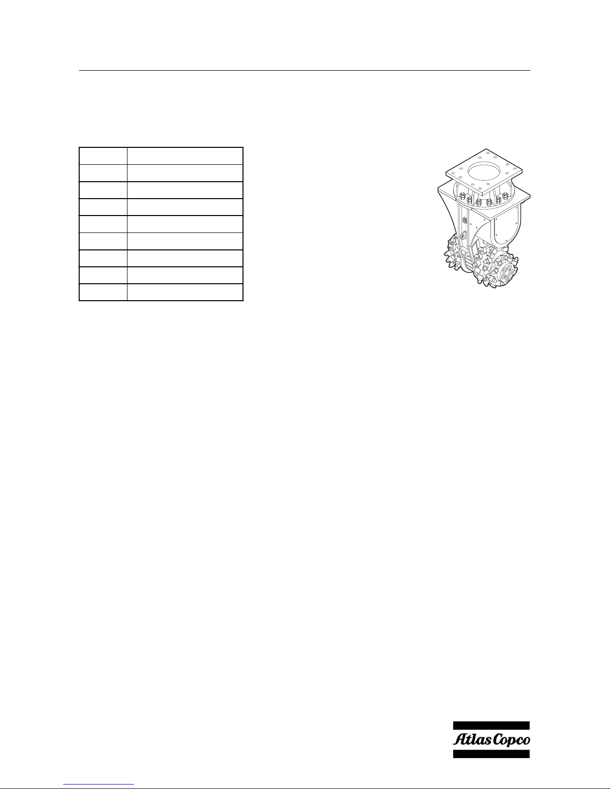
Safety and operating instructions
Transverse Drum Cutters
DC 200
DC 400
DC 600
DC 1000
DC 1200
DC 2000
DC 2100
DC 2900
Valid from serial number
DEQ161115
DEQ140244
DEQ140245
DEQ140246
DEQ161163
DEQ132047
DEQ140172
DEQ161168
DC
200, 400, 600, 1000, 1200, 2000, 2100, 2900
© Construction Tools GmbH | 3390 5192 01 | 2016-12-01
Original instructions
Page 2

Page 3

Contents
Introduction .................................................................................................................................................... 7
About these Safety and Operating Instructions .................................................................................... 7
Safety instructions ......................................................................................................................................... 8
Signal words ............................................................................................................................................. 8
Qualification .............................................................................................................................................. 9
Intended use .............................................................................................................................................. 9
Use other than intended ........................................................................................................................... 9
Protective equipment ............................................................................................................................. 10
Carrier, precautions ................................................................................................................................ 10
Transport, precautions ........................................................................................................................... 10
Hydraulic installation, precautions ....................................................................................................... 11
Media/consumables, precautions .......................................................................................................... 11
Explosion and fire, precautions ............................................................................................................ 12
Electrical shock, precautions ................................................................................................................ 12
Falling stones, precautions ................................................................................................................... 12
Emissions, precautions ......................................................................................................................... 13
Handling machines, precautions .......................................................................................................... 13
Repair, precautions ................................................................................................................................ 14
Maintenance works not allowed by Atlas Copco ................................................................................. 14
Changes to the hydraulic attachment, precautions ............................................................................ 14
Environmental pollution, precautions .................................................................................................. 15
Overview ....................................................................................................................................................... 16
Equipment description ........................................................................................................................... 16
Function ................................................................................................................................................... 16
Modules ................................................................................................................................................... 16
Signs / labels ........................................................................................................................................... 18
Name plate .......................................................................................................................................... 18
Labels .................................................................................................................................................. 19
Applications ............................................................................................................................................ 19
Working area and hazardous area ........................................................................................................ 19
Removing the packaging ....................................................................................................................... 20
Scope of delivery .................................................................................................................................... 20
Standard round attack picks ................................................................................................................ 21
Transport ...................................................................................................................................................... 22
Transport using a crane ......................................................................................................................... 22
Transport using a forklift truck .............................................................................................................. 23
Transport using a truck .......................................................................................................................... 23
Installation .................................................................................................................................................... 24
Media/consumables ................................................................................................................................ 24
Mineral hydraulic oil ............................................................................................................................. 24
Non-mineral hydraulic oil ..................................................................................................................... 24
Gear oil ................................................................................................................................................ 24
Preconditions for the carrier ................................................................................................................. 24
Preconditions for adapter plate ............................................................................................................. 25
Manufacturing the adapter plate ........................................................................................................... 25
Attaching the hydraulic attachment to the carrier ............................................................................... 26
Mechanical mounting aspects ............................................................................................................. 26
First installation .................................................................................................................................... 27
Making the hydraulic connections ........................................................................................................ 28
Mechanical mounting aspects ............................................................................................................. 29
Removing the hydraulic attachment from the carrier ......................................................................... 30
Operation ...................................................................................................................................................... 31
DC 200, 400, 600, 1000, 1200, 2000, 2100, 2900 Contents
© Construction Tools GmbH | 3390 5192 01 | 2016-12-01
Original instructions
3
Page 4

Preparations before starting .................................................................................................................. 32
Commissioning ....................................................................................................................................... 33
Checks during commissioning ............................................................................................................. 33
Switching the transverse drum cutter on and off ................................................................................ 33
Functional test ........................................................................................................................................ 33
Correct operation .................................................................................................................................... 34
Prohibited operation ............................................................................................................................... 35
Cylinder end positions ......................................................................................................................... 35
Moving the carrier ................................................................................................................................ 35
Lifting/Transporting .............................................................................................................................. 35
Impacting/chopping .............................................................................................................................. 36
Activities after use .................................................................................................................................. 36
Turning the transverse drum cutter ...................................................................................................... 36
Maintenance ................................................................................................................................................. 38
Maintenance works not allowed by Atlas Copco ................................................................................. 39
Maintenance schedule ........................................................................................................................... 40
Depressurising the hydraulic system ................................................................................................... 41
Cleaning ................................................................................................................................................... 41
Checking bolted connections ................................................................................................................ 41
Checking the hydraulic attachment and adapter plate for cracks ..................................................... 42
Checking the adapter plate bolts for wear ........................................................................................... 42
Change gear oil ....................................................................................................................................... 42
Oil change intervals ............................................................................................................................. 42
Preparation .......................................................................................................................................... 42
Drain off gear oil .................................................................................................................................. 42
Fill up gear oil ...................................................................................................................................... 43
Check the round attack picks ................................................................................................................ 44
Replace round attack picks ................................................................................................................... 44
Replace round attack pick with knock on retainer ............................................................................... 45
Replace round attack pick with retaining sleeve .................................................................................. 46
Replace round attack picks with quick snap retainer ........................................................................... 47
Replace round attack picks with retaining ring .................................................................................... 48
Replace cutter drums ............................................................................................................................. 49
Disassemble cutter drums ................................................................................................................... 49
Assemble cutter drums ........................................................................................................................ 50
Assemble and disassemble rotatable upper part ................................................................................ 52
Disassemble rotatable upper part ........................................................................................................ 52
Assemble rotatable upper part ............................................................................................................. 52
Checking hydraulic lines ....................................................................................................................... 53
Checking and cleaning the hydraulic oil filter of the carrier .............................................................. 53
Replace hydraulic hoses ........................................................................................................................ 54
Actions following maintenance ............................................................................................................. 54
Bolt connections/ Tightening torques .................................................................................................. 55
Troubleshooting ........................................................................................................................................... 57
Faults table .............................................................................................................................................. 57
Cutter drums do not turn / are blocked ................................................................................................ 58
Cutter drums turn too slowly ................................................................................................................. 58
Transverse drum cutter stops moving with light pressure ................................................................ 58
Unusual oscillation of the cutter drums ............................................................................................... 59
Round attack picks do not turn ............................................................................................................. 59
Unusually loud gear noise ..................................................................................................................... 59
Unusually loud noise from the hydraulic motor .................................................................................. 59
Overpressure cover for the hydraulic motor deformed, oil leak on sealing surface, oil leak at the
pressure limiting valve ........................................................................................................................... 60
Behaviour following fault elimination ................................................................................................... 60
Repair ............................................................................................................................................................ 61
Contents DC 200, 400, 600, 1000, 1200, 2000, 2100, 2900
4 © Construction Tools GmbH | 3390 5192 01 | 2016-12-01
Original instructions
Page 5

Sending in the hydraulic attachment for repairs ................................................................................. 61
Storage .......................................................................................................................................................... 62
Transverse drum cutter .......................................................................................................................... 62
Short storage ....................................................................................................................................... 62
Long storage ........................................................................................................................................ 62
Cutter drums ........................................................................................................................................... 62
Round attack picks ................................................................................................................................. 62
Disposal ........................................................................................................................................................ 63
Transverse drum cutter .......................................................................................................................... 63
Hydraulic hoses ...................................................................................................................................... 63
Hydraulic oil ............................................................................................................................................ 63
Gear oil .................................................................................................................................................... 63
Technical specifications .............................................................................................................................. 64
Appendix ................................................................................................................................................. 66
Hydraulic installation version 1 for hydraulic hammer ......................................................................... 66
Hydraulic installation version 2 for hydraulic shear systems ............................................................... 67
Hydraulic settings DC 200 ................................................................................................................... 68
Hydraulic settings DC 400 ................................................................................................................... 69
Hydraulic settings DC 600 ................................................................................................................... 70
Hydraulic settings DC 1000 ................................................................................................................. 71
Hydraulic settings DC 1200 ................................................................................................................. 72
Hydraulic settings DC 2000 ................................................................................................................. 73
Hydraulic settings DC 2100 ................................................................................................................. 74
Hydraulic settings DC 2900 ................................................................................................................. 75
EC Declaration of Conformity (EC Directive 2006/42/EC) ........................................................................ 76
DC 200, 400, 600, 1000, 1200, 2000, 2100, 2900 Contents
© Construction Tools GmbH | 3390 5192 01 | 2016-12-01
Original instructions
5
Page 6

Page 7

Introduction
Thank you for choosing an Atlas Copco product!
We have been working according to a customeroriented approach since 1873. Our innovative and
ergonomic solutions help our customers lower
costs and achieve better business results.
Atlas Copco has a worldwide, comprehensive
sales and service network of Customer Centers
and dealers. Our professionals are specialists with
a thorough product knowledge and considerable
application experience.
This allows us to offer our customers effective
service and know-how throughout the world,
enabling them to achieve greater operating
efficiency.
Construction Tools GmbH
P.O. Box: 102152
Helenenstraße 149
D - 45021 Essen
Tel.: +49 201 633-0
About these Safety and
Operating Instructions
The aim of these Instructions is to familiarise you
with the safe and effective operation of the
hydraulic attachment. You will also find instructions
for regular maintenance activities for the hydraulic
attachment in this document.
Please read these Instructions carefully prior to the
first attachment and use of the hydraulic
attachment.
The different designation of the texts means as
follows:
►
Action step in a safety instruction
♦
Action step
1.
2.
Established operation process
A
B
C
Explanation of the elements of a drawing
•
•
•
Listing
Symbols used in illustrations have the following
meanings:
permitted operation
prohibited operation
DC 200, 400, 600, 1000, 1200, 2000, 2100, 2900 Safety and operating instructions
© Construction Tools GmbH | 3390 5192 01 | 2016-12-01
Original instructions
7
Page 8

Safety instructions
This is the safety alert symbol. It is used to alert you to
potential personal injury hazards. Obey all safety
messages that follow this symbol to avoid possible
injury or death.
Read these Safety and operating instructions and
specifically all safety instructions before using the
hydraulic attachment. This will:
•
prevent the risk of injuries and fatal accidents
for yourself and others,
•
protect the hydraulic attachment and other
property against material damage,
•
protect the environment against environmental
damage.
Follow all instructions in these Safety and
operating instructions.
Store these Safety and operating instructions in
the document compartment of the carrier cab.
Anyone
•
transporting,
•
installing or removing,
•
operating,
•
maintaining,
•
repairing,
•
storing or
•
disposing of
the hydraulic attachment must have read and
understood these Safety and operating
instructions.
These Safety and operating instructions belong to
the hydraulic attachment. Keep it for the life of the
product. Ensure, if applicable, that any received
amendment is incorporated in the instructions.
Hand over the Safety and operating instructions if
ever you lend, rent out or sell the hydraulic
attachment.
All safety regulations listed in this manual comply
with the laws and regulations of the European
Union. Also observe the additional national/
regional regulations.
Hydraulic attachment operation outside the
European Union is subject to the laws and
regulations valid in the country of use. Please
observe any other, more stringent regional
regulations and legislation.
Read the carrier manufacturer's Safety and
operating Instructions before attaching the
hydraulic attachment to the carrier and operating it.
Observe all instructions.
Signal words
The signal words Danger, Warning, Caution, and
Notice are used as follows in these Safety and
operating instructions:
DANGER indicates a hazardous situation
which, if not avoided, will result in
death or serious injury.
WARNING indicates a hazardous situation
which, if not avoided, could result
in death or serious injury.
CAUTION indicates a hazardous situation
which, if not avoided, could result
in minor or moderate injury.
NOTICE The signal word NOTICE is used
to address practices related to
possible property damage but not
related to personal injury.
Safety and operating instructions DC 200, 400, 600, 1000, 1200, 2000, 2100, 2900
8 © Construction Tools GmbH | 3390 5192 01 | 2016-12-01
Original instructions
Page 9

Qualification
Transporting the hydraulic attachment is only
permitted if carried out by people who:
•
are authorised to operate a crane or a forklift
truck according to the applicable national
provisions,
•
know all the relevant national/regional safety
provisions and accident prevention rules,
•
have read and understood the safety and
transport chapter of these Safety and operating
instructions.
First installation and commissioning of the
hydraulic attachment is only permitted if carried out
by people who:
•
are authorised by Construction Tools GmbH,
•
know all the relevant national/regional safety
provisions and accident prevention rules,
•
have read and understood these Safety and
operating instructions.
Installing, maintaining, storing and disposing of
the hydraulic attachment are only permitted if
carried out by people who:
•
know all the relevant national/regional safety
provisions and accident prevention rules,
•
have read and understood these Safety and
operating instructions.
Operating the hydraulic attachment is only
permitted if carried out by qualified carrier drivers.
Carrier drivers are qualified if they:
•
have been trained to operate a carrier
according to the national regulations,
•
know all the relevant national/regional safety
provisions and accident prevention rules,
•
have read and understood these Safety and
operating instructions.
Testing the hydraulic installation is only
permitted if carried out by professionals.
Professionals are people who are authorised to
approve a hydraulic installation for operation
according to the national regulations.
Repairing the hydraulic attachment is only
permitted if carried out by professionals trained by
Construction Tools GmbH. These professionals
must have read and understood these Safety and
operating instructions. They must follow all safety
instructions and guidelines for repair. Otherwise
the operational safety of the hydraulic attachment
is not guaranteed.
Personnel (carrier operator, maintenance
personnel) must receive instructions from the
operator regularly. For the purpose of improved
traceability, the provision of instructions must be
recorded.
Intended use
Only attach the transverse drum cutter to a
hydraulic carrier of a suitable load-bearing
capacity. Read the carrier manufacturer's Safety
and operating instructions before attaching the
transverse drum cutter to the carrier and operating
it. Observe all instructions.
The transverse drum cutter is intended exclusively
for mounting on a hydraulic excavator or, following
agreement with the Atlas Copco Customer Center/
dealer in your area, with another carrier.
The transverse drum cutter serves exclusively to
cut:
•
Rock
•
Concrete (reinforced and non-reinforced)
•
Asphalt
•
Frozen soil
•
Ice
Furthermore, the transverse drum cutter is suitable
for cutting ditches and tunnels. The transverse
drum cutter can be used to a depth of 30 m under
water.
When cutting with the transverse drum cutter,
check the compressive strengths of the rock to be
cut (see chapter Technical specifications).
Intended use also includes adhering to all
specifications contained in this manual.
Any further use which exceeds or is contrary to the
intended use is considered inappropriate use.
Use other than intended
Misusing the transverse drum cutter or the boom
can lead to dangerous situations.
•
Do not use the transverse drum cutter in areas
with a risk for explosions.
•
Do not cut any materials other than those
mentioned in chapter Intended use.
•
Do not carry out any impacting work.
•
Do not operate the transverse drum cutter if
picks are broken.
•
Do not use the transverse drum cutter as a
device for lifting people or materials.
•
Do not use the transverse drum cutter as a
surface for carrying or transporting machines,
materials or tools.
•
Do not use the transverse drum cutter to take
the weight of the carrier.
Claims of any kind as a result of damages arising
from misuse are excluded.
DC 200, 400, 600, 1000, 1200, 2000, 2100, 2900 Safety and operating instructions
© Construction Tools GmbH | 3390 5192 01 | 2016-12-01
Original instructions
9
Page 10

Protective equipment
Personal protective equipment must comply with
the applicable health and safety regulations.
Always wear the following personal protective
equipment:
•
protective helmet
•
safety glasses with side protectors
•
protective gloves
•
protective shoes
•
warning vest
•
Light respiratory protection
•
Protective work clothing
Protective work clothing is tight-fitting work
clothing with low resistance to tearing, with tight
sleeves and without projecting parts. It is
primarily used to protect against entanglement
by moving machine parts. Do not wear rings,
chains or other jewellery.
Carrier, precautions
WARNING Falling carrier
If the load-bearing capacity of the carrier used is
insufficient, the carrier will not be stable. It can
topple over and cause injuries and damage.
Using a carrier whose load-bearing capacity is too
high will greatly burden the hydraulic attachment
causing it to wear faster.
►
Only attach the hydraulic attachment to a
hydraulic carrier of a suitable load-bearing
capacity.
►
The carrier must remain stable at all times.
►
Read the carrier manufacturer's Safety and
operating Instructions before attaching the
hydraulic attachment to the carrier and
operating it. Observe all instructions.
Transport, precautions
WARNING Risk of death due to suspended
loads
When lifting loads these can swing out and fall.
This can result in serious injuries or even death.
►
Never stand underneath or in the swinging
range of suspended loads.
►
Only move loads under supervision.
►
Only use approved lifting equipment and lifting
gear with sufficient load bearing capacity.
►
Do not use worn lifting gear (ropes, belts,
chains, shackles etc.).
►
Do not place lifting gear such as ropes and
belts on sharp edges or corners, do not knot
these or twist them.
►
When leaving the workplace, set down the load.
WARNING Injury due to swivelling load
When transporting the load by crane it can swivel
and cause severe injuries and considerable
damage to property.
►
Ensure that no personnel, objects or obstacles
are located in the swivel range of the load.
Safety and operating instructions DC 200, 400, 600, 1000, 1200, 2000, 2100, 2900
10 © Construction Tools GmbH | 3390 5192 01 | 2016-12-01
Original instructions
Page 11

Hydraulic installation,
precautions
WARNING Hydraulic pressure too high
If the hydraulic pressure is too high, the parts of
the hydraulic attachment will be exposed to
excessively high loads. Parts can break loose or
burst causing serious injuries.
►
Lay the drain line of the pressure relief valve
directly in the tank to ensure the safe
functioning of the pressure relief valve!
►
The pressure relief valve must be set at the
maximum static pressure.
►
The pressure relief valve setting must be
checked to ensure that the maximum static
pressure (see chapter Technical specifications)
of the hydraulic installation is not exceeded at
any time. Attach a lead seal to the pressure
relief valve.
►
Prior to their first use, the safety facilities on the
hydraulic installation must be checked by a
professional/authorised monitoring body for
their quality (CE mark etc.), suitability and
proper functioning.
►
If any significant changes are made to the
hydraulic installation, a new acceptance
inspection is to be carried out in accordance
with the relevant national safety provisions.
WARNING Hot hydraulic oil squirting out
The hydraulic system is under high pressure.
Hydraulic lines may spring a leak or burst.
Hydraulic oil squirting out can lead to serious
injury.
►
When attaching the hydraulic attachment do not
route any hydraulic lines through the carrier's
cab.
►
Only use hydraulic lines which comply with the
following quality requirements:
Hydraulic hoses with 4 reinforcement steel
wires 4SP and 4SH according to DIN EN 856,
Hydraulic hoses with high tensile steel wire
braid 1SN and 2SN according to DIN EN 853,
Hydraulic pipes, seamless cold-drawn steel
pipes to DIN EN 10305.
Media/consumables,
precautions
WARNING Hot hydraulic oil under high
pressure
Hydraulic oil will squirt out under high pressure if
there is a leakage. The jet of oil might penetrate
people's skin and cause permanent damage. Hot
hydraulic oil can cause burns.
►
Never use your hands to find leaks.
►
Always keep your face away from a possible
leak.
►
If hydraulic oil has penetrated your skin consult
a doctor immediately.
WARNING Hydraulic oil spills
Spilt hydraulic oil can make a floor slippery. If
people slip they can be injured. Hydraulic oil is
environmentally harmful and must not penetrate
the ground or enter the water table or water
supplies.
►
Make sure not to spill any hydraulic oil.
►
Immediately clean the floor if you have spilt
hydraulic oil.
►
Observe all safety and environmental protection
provisions when handling hydraulic oil.
WARNING Skin infections/diseases due to
oil and grease
Hydraulic oil and grease can cause rashes (or
even eczema) if they come into contact with the
skin.
►
Avoid all skin contact with hydraulic oil and
grease.
►
Use a suitable skin protection product.
►
Always wear safety gloves when working with
hydraulic oil or grease.
►
Immediately clean any skin that has been
contaminated by oil or grease with water and
soap.
DC 200, 400, 600, 1000, 1200, 2000, 2100, 2900 Safety and operating instructions
© Construction Tools GmbH | 3390 5192 01 | 2016-12-01
Original instructions
11
Page 12

Explosion and fire,
precautions
DANGER Explosion and fire
Explosions cause serious injury or death.
If the hydraulic attachment encounters explosives
in operation, it may cause an explosion.
►
Never operate the hydraulic attachment in the
direct vicinity of explosives.
►
Make sure that no explosives are hidden in the
ground.
►
Check gas line position plans of the complete
construction area.
DANGER Explosion and fire
Operating the hydraulic attachment may create
sparks which ignite highly flammable gases.
This may lead to fire or an explosion.
►
Never work in an environment with highly
flammable substances.
►
Make sure that there are no hidden sources of
gas in the work area.
►
Check gas line position plans of the complete
construction area.
DANGER Explosion and fire
Dust-rich air can form an explosive atmosphere
which may ignite when operating the hydraulic
attachment.
This may lead to fire or an explosion.
►
Never operate the hydraulic attachment in an
explosion-hazard atmosphere.
►
Always provide sufficient ventilation when
working in buildings or in a confined area.
Electrical shock, precautions
DANGER Electrical shock
Any contact of the hydraulic attachment with
electric circuits or other sources of electricity will
lead to an electric shock, resulting in serious injury
or death. The hydraulic attachment is not
electrically insulated.
►
Never work in the vicinity of electric circuits or
other sources of electricity.
►
Make sure that there are no hidden circuits in
the work area.
►
Check wiring diagrams.
Falling stones, precautions
DANGER Fragments flying around
Fragments of material which come loose while
operating the hydraulic attachment may be flung
away and can cause serious injury if people are hit
by them. Small objects falling from a great height
can also cause serious damage.
During hydraulic attachment operation the danger
zone is considerably greater than during the
excavation operation due to fragments of stone
and pieces of steel flying around, and for this
reason the danger zone must, depending on the
type of material to be worked on, be enlarged
correspondingly, or secured in a suitable manner
through corresponding measures.
►
Secure the danger zone.
►
Ensure that no persons are within a distance of
15 metres during cutting work.
►
Ensure that no persons are within a distance of
50 metres during cutting work on reinforced
steel.
►
Stop the hydraulic attachment immediately if
anyone enters the danger zone.
►
Close the windscreen and the side windows of
the driver's cab.
Safety and operating instructions DC 200, 400, 600, 1000, 1200, 2000, 2100, 2900
12 © Construction Tools GmbH | 3390 5192 01 | 2016-12-01
Original instructions
Page 13

Emissions, precautions
WARNING Noise hazard
Operating the hydraulic attachment creates a loud
noise. Long term high sound pressure level can
affect your hearing.
►
Wear suitable hearing protection.
WARNING Lung disease
Dust may be generated when operating the
hydraulic attachment. If dust from rocks or silica
dust, produced when operating the hydraulic
attachment on rocks, concrete, asphalt or other
such materials, is inhaled this may lead to silicosis
(dust lungs, a severe lung disease). Silicosis is a
chronic disease which may lead cancer and death.
►
Wear a suitable breathing mask.
WARNING Vibration hazards
When working with the transverse drum cutter
severe vibrations can occur and may cause
considerable significant injuries and chronic
damage to health.
►
Operate the transverse drum cutter with a
constant load, in order to minimise existing
vibrations.
►
Avoid abrupt starting up or stopping of the
cutter drums.
WARNING Risk of death if exhaust gases
are not vented
When working in buildings or tunnels, exhaust
gases from the carrier (diesel motor) can collect
and cause poisoning or even death.
►
Effectively vent exhaust gases from buildings or
tunnels using a ventilation system.
►
Keep the cabin doors of the carrier closed.
WARNING Hot surfaces
The cutter drums of the transverse drum cutter can
become very hot in operation. Skin contact with hot
surfaces results in severe burns to the skin.
►
Always wear heat-resistant protective work
clothes and protective gloves, when working in
close proximity to hot surfaces.
►
Prior to all work, check the transverse drum
cutter to ensure that all surfaces have cooled to
the ambient temperature.
Handling machines,
precautions
WARNING Injuries due to incorrect
operation
Incorrect operation can result in severe injuries
and may cause considerable damage to property.
►
Carry out all operating steps in accordance with
these Safety and operating instructions.
►
Prior to starting work, ensure that:
•
All covers and safety devices are installed
and are fully functional.
•
No persons are in the hazardous area.
►
Never switch off any safety devices during
operations or bridge these.
WARNING Injuries due to unclean
workplace
A dirty workplace can cause accidents and may
result in severe injuries.
►
Always keep the accesses to the carrier cabin
clean.
►
Always keep the cabin windows clean.
►
Do not leave parts or objects lying around the
working area.
WARNING Injuries due to missed
inspection and repair work
Disregarding or neglecting daily inspections can
result in serious accidents and lead in turn to the
severe injuries associated with them.
►
Carry out all daily inspections before and after
work.
►
Report any faults or damage to maintenance
personnel immediately and instruct them to
repair them.
►
Only restart the carrier once the fault or
damage has been repaired.
WARNING Narcotics, alcohol and drugs
Narcotics, alcohol and medicinal drugs make their
users less alert and affect their ability to
concentrate. Negligence and incorrectly assessing
a situation can result in serious injury or death.
►
Never work on or with the hydraulic attachment
when under the influence of narcotics, alcohol
or drugs which affect your alertness.
►
Never allow other people who are under the
influence of narcotics, alcohol or drugs which
affect their alertness to work on or with the
hydraulic attachment.
DC 200, 400, 600, 1000, 1200, 2000, 2100, 2900 Safety and operating instructions
© Construction Tools GmbH | 3390 5192 01 | 2016-12-01
Original instructions
13
Page 14

Repair, precautions
Maintenance work must be conducted exclusively
by authorised and trained maintenance personnel.
Maintenance works not allowed by Atlas
Copco
Some maintenance activities must be carried out
exclusively by Atlas Copco. If such maintenance
activities are required, consult the Atlas Copco
customer center/Dealer in your area in order to
ensure that they proceed safely.
The following maintenance activities are not
allowed by Atlas Copco:
•
Repairs to the gear
•
Replacing wear sleeves and pick boxes
•
Welding work on the cutter drums
•
Welding work on the gear housing
Changes to the hydraulic
attachment, precautions
WARNING Changes to the hydraulic
attachment
Changes to the hydraulic attachment or the
adapter plate may lead to serious injury.
►
Never carry out any changes to the hydraulic
attachment or the adapter plate.
►
Only use original parts or accessories approved
by Atlas Copco.
►
Modifications that entail new hazards may
require a new procedure for assessing
conformity.
WARNING Injuries due to the use of
incorrect spare parts
The use of incorrect or defective spare parts can
result in risks to personnel as well as damage,
malfunctioning or a total failure of the transverse
drum cutter.
►
Only use original parts or accessories approved
by Atlas Copco.
►
If there are any questions, consult the Atlas
Copco Customer Center/dealer in your area.
Safety and operating instructions DC 200, 400, 600, 1000, 1200, 2000, 2100, 2900
14 © Construction Tools GmbH | 3390 5192 01 | 2016-12-01
Original instructions
Page 15

Environmental pollution,
precautions
NOTICE Environmental pollution due to hydraulic
oil
Hydraulic oil is permanently environmentally
harmful. Escaped hydraulic oil will lead to
groundwater and soil contamination. Organisms
may die.
►
Collect any hydraulic oil which escapes to avoid
environmental pollution. For minor volumes use
an absorbing medium (in case of an emergency
use soil). In case of major leakages contain the
hydraulic oil. It must not drain off and penetrate
the ground or enter the water table or water
supplies.
►
Collect contaminated absorbing medium or soil
in a watertight box/container and close it tight.
►
Contact an authorized waste management
company.
►
Dispose of all contaminated material in
accordance with the applicable environmental
regulations.
DC 200, 400, 600, 1000, 1200, 2000, 2100, 2900 Safety and operating instructions
© Construction Tools GmbH | 3390 5192 01 | 2016-12-01
Original instructions
15
Page 16
Overview
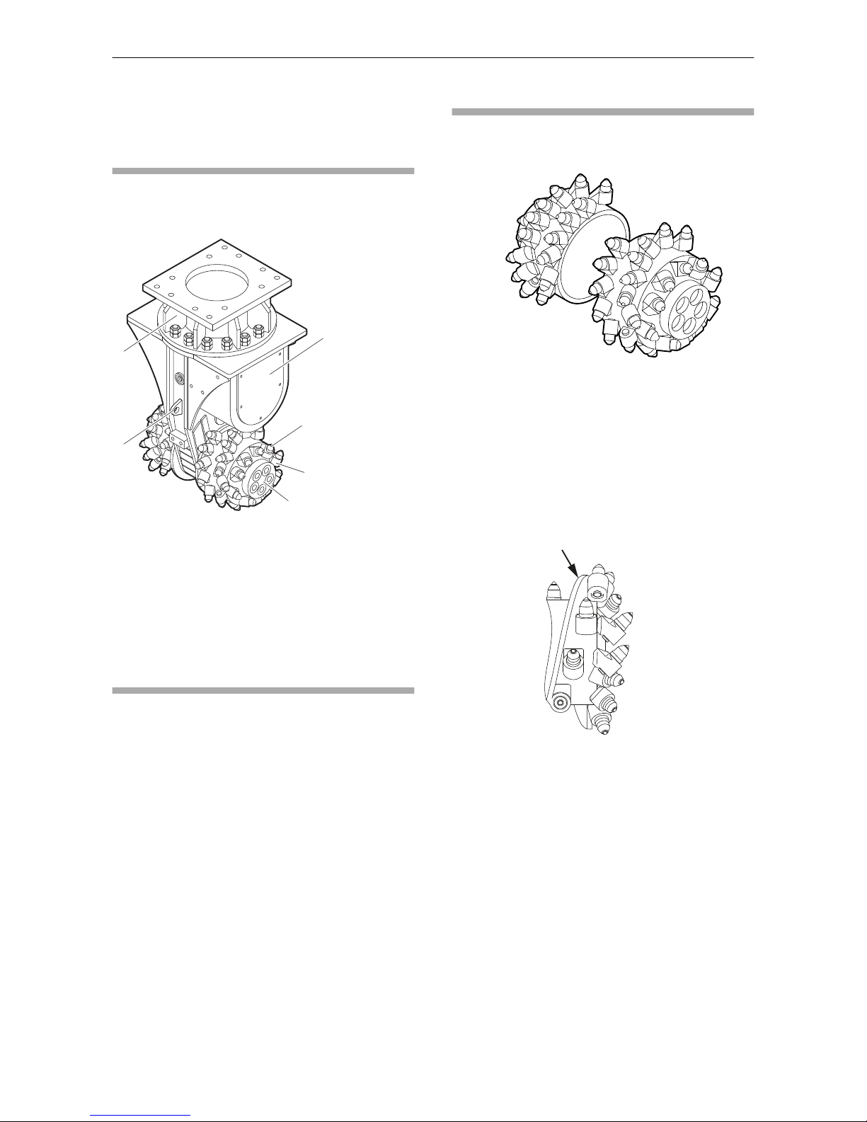
Equipment description
The illustration gives an overview of the main parts
and components of the hydraulic attachment.
Actual details may differ.
D
E
F
A
B
C
A. Gear housing
B. Round attack pick
C. Pick box
D. Cutter drum
E. Transport lug
F. Rotatable upper part
Function
The operation of a transverse drum cutter is
described in a simplified version below:
The transverse drum cutter is an attachment for
hydraulic carriers. The cutter drums are powered
by the hydraulic motor and the gear of the
transverse drum cutter. The round attack picks are
attached to the cutter drums at a defined angle. A
rotating motion of the cutter drums facilitates the
cutting process and thus reduces the size of the
rock.
Modules
Cutter drums
The transverse drum cutter is equipped with one
left and one right cutter drum. These cutter drums
are fastened by means of screws and special
clamping sleeves directly to the drive shafts. A
certain number of pick boxes are attached to the
surface of the cutter drums. These hold the round
attack picks in position.
The cutter drums can be designed with charging
spirals (see arrow).
Safety and operating instructions DC 200, 400, 600, 1000, 1200, 2000, 2100, 2900
16 © Construction Tools GmbH | 3390 5192 01 | 2016-12-01
Original instructions
Page 17

Transport lug
E
The transport lug (E) serves as an anchor point for
the lifting gear when transporting the transverse
drum cutter.
Rotatable upper part
The transverse drum cutter is fastened to a
suitable adapter plate on the carrier boom via the
rotatable upper part. The rotatable upper part is
bolted to the adapter plate. Additionally, the
transverse cutter drum can be rotated via the
rotatable upper part relative to the axis of the
boom.
Gear housing
The gear housing contains a spur gear driven by a
hydraulic motor. The gear's drive shafts turn the
cutter drums. The hydraulic motor transfers the
drive moment through the gear to the cutter drums.
Round attack picks
The round attack picks are made of steel and have
a brazed tungsten carbide tip. The round attack
picks are held in the pick boxes.
The appearance of the round attack picks may
deviate from the image shown here.
DC 200, 400, 600, 1000, 1200, 2000, 2100, 2900 Safety and operating instructions
© Construction Tools GmbH | 3390 5192 01 | 2016-12-01
Original instructions
17
Page 18

Pick boxes
The pick boxes are welded onto the cutter drums
for holding round attack picks. Some pick boxes
may have a wear sleeve, which can be exchanged.
Signs / labels
WARNING Missing warnings
The name plate and the labels on the hydraulic
attachment contain important information about the
hydraulic attachment and for personal safety. A
missing warning can lead to overlooking or
misinterpretation of possible risks and cause
personal hazards. The signs and labels must
always be clearly legible.
►
Immediately replace any defective name plates
and labels.
►
Use the spare parts list to order new name
plates and labels.
Name plate
A B C D E F G H
Construction Tools GmbH
A. Model
B. Year of construction of hydraulic attachment
C. Max. hydraulic pressure
D. Weight of hydraulic attachment
E. Serial number
F. Name and address of manufacturer
G. The warning symbol and the book symbol
indicate that the Safety and Operating
Instructions must be read prior to use of the
hydraulic tool and in particular the chapter on
Safety.
H. The CE symbol indicates that the hydraulic
attachment was produced in conformity with
CE. You can find further information about this
in the enclosed EC Declaration of Conformity.
Safety and operating instructions DC 200, 400, 600, 1000, 1200, 2000, 2100, 2900
18 © Construction Tools GmbH | 3390 5192 01 | 2016-12-01
Original instructions
Page 19
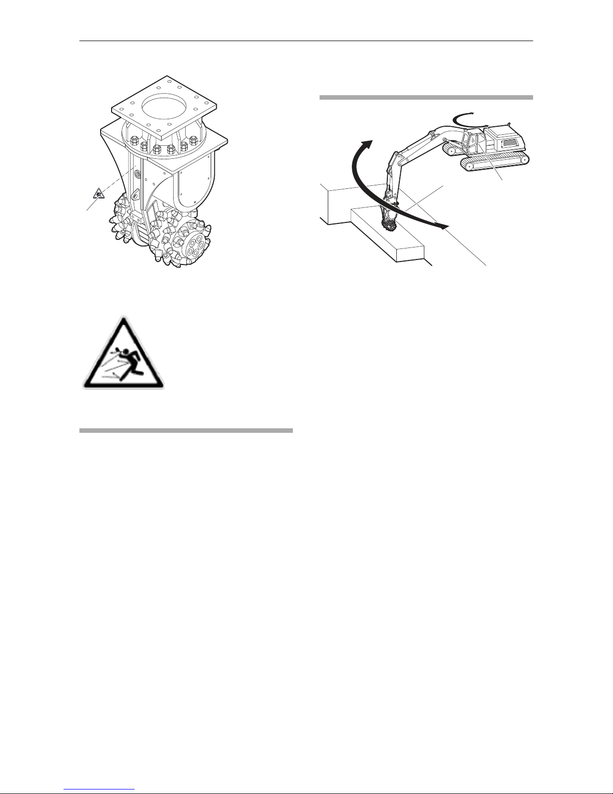
Labels
A
A. Danger zone
Danger zone
No persons should be within the
danger zone. Fragments of
material which come loose while
operating the hydraulic
attachment may be flung away
and can cause serious injury if
people are hit by them. Small
objects falling from a great height
can also cause serious damage.
Applications
The transverse drum cutter is suitable for use in
trenching and tunnelling, for demolition and
renovation works, quarrying and in special
underground engineering.
Working area and hazardous
area
B
A
A. Working area for operating personnel
B. Hazardous area when working with the
transverse drum cutter
•
The working area for the operating personnel is
in the cabin of the carrier.
•
The hazardous area is in the direct vicinity of
the transverse drum cutter.
•
Whilst operating the transverse drum cutter, the
minimum distance around the carrier is 15
metres.
•
When cutting reinforced concrete, the minimum
distance around the carrier is 50 metres.
DC 200, 400, 600, 1000, 1200, 2000, 2100, 2900 Safety and operating instructions
© Construction Tools GmbH | 3390 5192 01 | 2016-12-01
Original instructions
19
Page 20

Removing the packaging
◆
Remove all the packaging material.
◆
Dispose of it in accordance with the applicable
provisions.
◆
Check that the delivery is complete.
◆
Check the delivery for visual damage.
◆
If any defects are found, consult the Atlas
Copco Customer Center/dealer in your area.
Scope of delivery
The transverse drum cutter is delivered complete
with:
•
Transverse drum cutter including rotatable
upper part
•
Safety and operating instructions
•
Spare parts list
•
EC Declaration of Conformity
•
Hoses:
- Pressure line
- Tank line including precharge valve
- Leakage oil line
•
Overpressure cover plate including O-ring and
screws
•
Set of standard round attack picks including
retainers (see table below)
•
Set of tools for round attack pick assembly and
disassembly (see table below)
Safety and operating instructions DC 200, 400, 600, 1000, 1200, 2000, 2100, 2900
20 © Construction Tools GmbH | 3390 5192 01 | 2016-12-01
Original instructions
Page 21

Standard round attack picks
Ø
T
L
H
L
S
Ø
H
Ø
S
Type Ø
S
Shaft diameter
L
S
Shaft length
Ø
H
Head diameter
L
H
Head length
Ø
T
Tip diameter
Locking system
DC 200 11.4 mm (0.45 in.) 26.0 mm (1.02 in.) 24.0 mm (0.94 in.) 28.0 mm (1.10 in.) 11.5 mm (0.45 in.) Knock on retainer
DC 400 20.0 mm (0.79 in.) 41.0 mm (1.61 in.) 38.0 mm (1.50 in.) 45.0 mm (1.77 in.) 12.0 mm (0.47 in.) Retainer sleeve
DC 600 22.0 mm (0.87 in.) 56.5 mm (2.22 in.) 38.0 mm (1.50 in.) 42.0 mm (1.65 in.) 12.0 mm (0.47 in.) Knock on retainer
DC 1000 25.0 mm (0.98 in.) 78.5 mm (3.09 in.) 60.0 mm (2.36 in.) 64.0 mm (2.52 in.) 17.0 mm (0.67 in.) Quick snap retainer
DC 1200 25.0 mm (0.98 in.) 78.5 mm (3.09 in.) 60.0 mm (2.36 in.) 64.0 mm (2.52 in.) 17.0 mm (0.67 in.) Quick snap retainer
DC 2000 30.0 mm (1.18 in.) 80.0 mm (3.15 in.) 70.0 mm (2.76 in.) 75.0 mm (2.95 in.) 17.0 mm (0.67 in.) Quick snap retainer
DC 2100 30.0 mm (1.18 in.) 80.0 mm (3.15 in.) 70.0 mm (2.76 in.) 75.0 mm (2.95 in.) 17.0 mm (0.67 in.) Quick snap retainer
DC 2900 30.0 mm (1.18 in.) 80.0 mm (3.15 in.) 70.0 mm (2.76 in.) 75.0 mm (2.95 in.) 19.0 mm (0.75 in.) Quick snap retainer
Set of tools for round attack pick
Type A B C D E F
DC 200
DC 400 x x x
DC 600 x x x x
DC 1000 x x x
DC 1200 x x x
DC 2000 x x x
DC 2100 x x x
DC 2900 x x x
A. Knock out tool
B. Knock out tool for stuck picks
C. Mounting tool for knock on retainer
D. Dismantling tool for knock on retainer
E. Puller tool for quick snap retainers
F. Puller for retainer sleeve picks
Special accessories as ordered:
•
e.g. adapter plate with Allen screws and pairs of lock washers
•
e.g. base plate to construct an adapter plate with Allen screws and pairs of lock washers
•
e.g. hydraulic fittings for the carrier
DC 200, 400, 600, 1000, 1200, 2000, 2100, 2900 Safety and operating instructions
© Construction Tools GmbH | 3390 5192 01 | 2016-12-01
Original instructions
21
Page 22
Transport
WARNING Hoist tipping over / hydraulic
attachment falling
The hydraulic attachment is heavy. The hoist/lifting
equipment and/or hydraulic attachment tipping
over or falling may cause serious injury and
material damage.
►
Only transport the hydraulic attachment with
lifting equipment with the right load-bearing
capacity for the weight of the hydraulic
attachment.
►
Only lift and secure the hydraulic attachment
with lifting gear (ropes, chains, shackles etc.)
with the right load-bearing capacity for the
weight to be lifted.
►
Make sure that there is nobody near or under
the suspended hydraulic attachment.
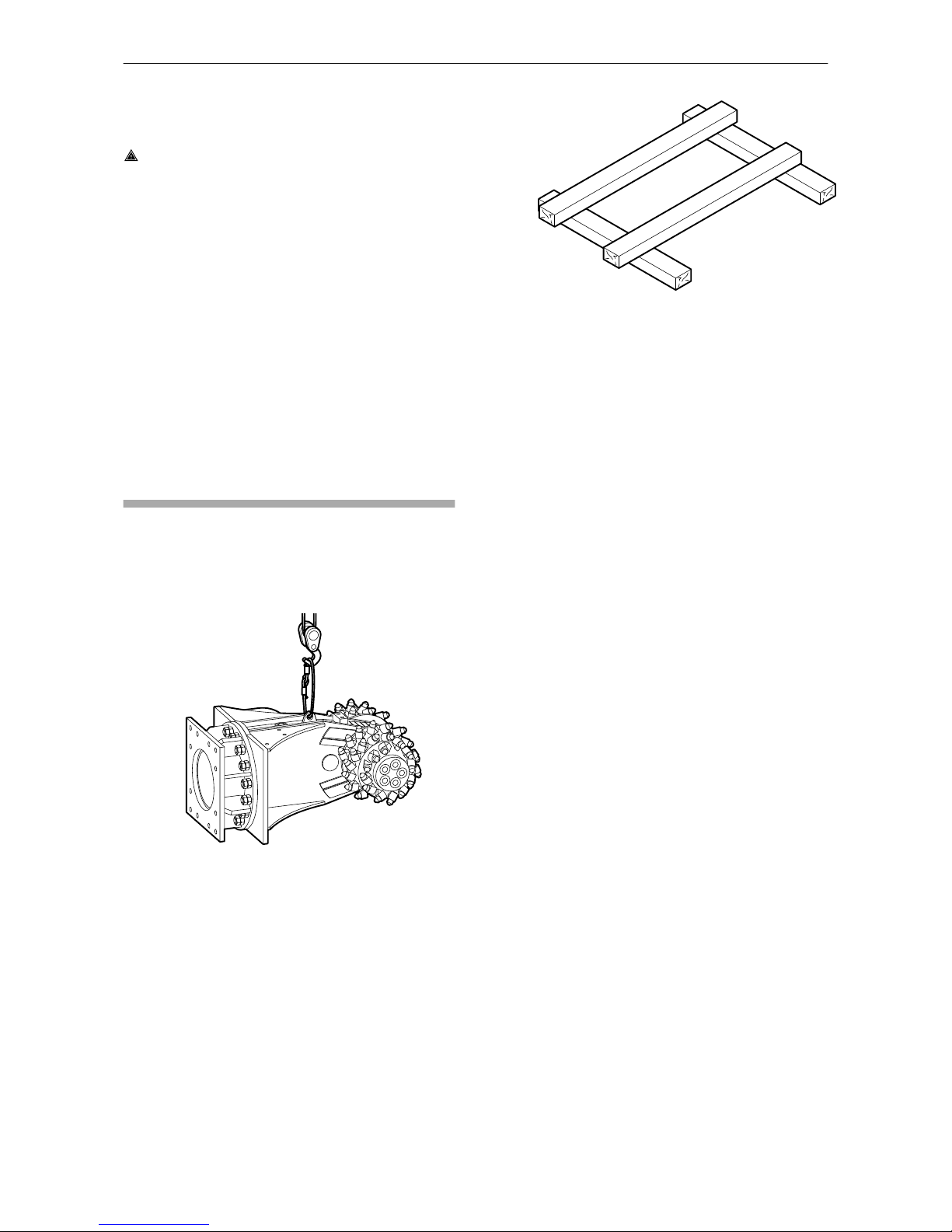
Transport using a crane
The transverse drum cutter is equipped with
transport lugs, for lifting by crane.
◆
Secure the hydraulic attachment with ropes or
chains as shown in the following illustration.
◆
Slowly lift the hydraulic attachment.
Ensure that the transverse drum cutter hangs
straight, if applicable observe any eccentric
centre of gravity.
◆
Place the transverse drum cutter on the
assembly stand.
Safety and operating instructions DC 200, 400, 600, 1000, 1200, 2000, 2100, 2900
22 © Construction Tools GmbH | 3390 5192 01 | 2016-12-01
Original instructions
Page 23
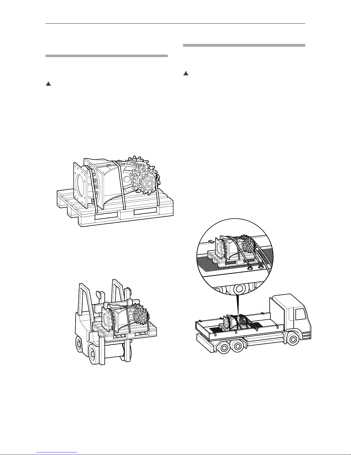
Transport using a forklift
truck
Always transport the transverse drum cutter whilst
secured to the assembly stand.
WARNING Hydraulic attachment tipping
over
The hydraulic attachment tipping off the fork of the
forklift truck or the assembly stand may cause
serious injury.
►
Place the hydraulic attachment on the assembly
stand.
►
Strap the hydraulic attachment to the assembly
stand using suitable strapping, as shown in the
illustration below.
►
Move the forks of the forklift truck under the
assembly stand so that the centre of gravity is
between the prongs.
◆
Move the forks of the forklift truck under the
assembly stand so that the hydraulic
attachment cannot tip over.
◆
Slowly lift the assembly stand with the hydraulic
attachment.
◆
Transport the assembly stand with the hydraulic
attachment to the location provided for.
Transport using a truck
Always transport the transverse drum cutter whilst
secured to the assembly stand.
WARNING Hydraulic attachment tipping
over / slipping
The hydraulic attachment slipping or tipping over
and falling from the loading area of a lorry may
cause serious injury.
►
Place the hydraulic attachment on the assembly
stand.
►
Strap the hydraulic attachment to the assembly
stand using suitable strapping (see illustration
in chapter Transport using a forklift truck).
►
Place the assembly stand with the hydraulic
attachment on an anti-slip mat.
►
Secure the hydraulic attachment to the loading
area with ropes or chains; use any available
transport lugs.
◆
Secure the hydraulic attachment on the
assembly stand and the loading surface as
shown in the following illustration.
◆
Observe all the applicable national/regional
regulations on securing loads.
DC 200, 400, 600, 1000, 1200, 2000, 2100, 2900 Safety and operating instructions
© Construction Tools GmbH | 3390 5192 01 | 2016-12-01
Original instructions
23
Page 24

Installation
WARNING Hot hydraulic oil squirting out
The hydraulic system is under high pressure. If
hydraulic connections come loose or are
disconnected, hydraulic oil will squirt out under
high pressure. Hydraulic oil squirting out can lead
to serious injury.
►
Depressurise the hydraulic system before
connecting or disconnecting the hydraulic
circuits of the hydraulic attachment (see chapter
Depressurising the hydraulic system).
WARNING Risk of death due to defective
first installation and commissioning
Faults during the first installation or commissioning
can lead to life-threatening situations and may
cause considerable damage to property.
►
Have the first installation and commissioning
exclusively conducted by authorised specialist
personnel.
►
Do not undertake unauthorised first installation
and commissioning.
Media/consumables
The following consumables are used when
operating the hydraulic attachment:
Mineral hydraulic oil
All hydraulic oil brands prescribed by the carrier
manufacturer are also suitable for use when
operating the hydraulic attachment.
However, the oil should comply with viscosity class
HLP 32 or higher.
In summer and in hot climates, oils of viscosity
class HLP 68 or higher should be used.
In all other respects the regulations of the carrier
manufacturer are to be taken into consideration.
Optimum viscosity range = 30 - 60 cSt
Max. start viscosity = 2000 cSt
Max. oil temperature = 80 °C
Special conditions apply to using the hydraulic
attachment at low temperatures (see chapter Low
ambient temperature).
◆
Check the oil filter!
An oil filter must be integrated in the tank line of
the hydraulic system. The maximum mesh
width allowed for the oil filter is 50 microns; it
must have a magnetic separator.
Non-mineral hydraulic oil
NOTICE Mixed hydraulic oil
Never mix mineral and non-mineral hydraulic oils!
Even small traces of mineral oil mixed in with nonmineral oil can result in damage to both the
hydraulic attachment and the carrier. Non-mineral
oil loses its biodegradability.
►
Only use one type of hydraulic oil.
If you are using non-mineral oil it is imperative that
the name of the oil in use be indicated when
returning the hydraulic attachment for repair.
In order to protect the environment or on technical
grounds, hydraulic oils are currently being used
which are not classified as HLP mineral oils.
Before using hydraulic oils of this kind it is
imperative to ask the carrier manufacturer whether
operations with such fluids are possible.
Our hydraulic attachments are basically designed
for use with mineral oils. Consult the Atlas Copco
Customer Center/Dealer in your area before using
other hydraulic oils approved by the carrier
manufacturer. Following initial assembly and after
any workshop repairs, our hydraulic attachments
are subjected to a test run on a test bed powered
by mineral oil.
Gear oil
Media /
consumables
Temperature range Part number
AC Fluid Traction
Gear 100
-15 to +40 °C
5 l (1.32 gal)
4812 0082 71
20 l (5.28 gal)
4812 0082 72
209 l (55.21 gal)
4812 0082 73
AC Fluid Gearbox
100
-20 to +30 °C
5 l (1.32 gal)
4812 0082 74
20 l (5.28 gal)
4812 0082 75
209 l (55.21 gal)
4812 0082 76
Preconditions for the carrier
The carrier must fulfil the following criteria in order
that a transverse drum cutter can be attached to it:
•
A complete hydraulic hammer or shearer line
right to the end of the carrier boom must be
available.
•
The motor's pressure line is set to max. 350
bar.
•
The pressure of the tank line is at least 5 bar
above the pressure of the case drain line.
Safety and operating instructions DC 200, 400, 600, 1000, 1200, 2000, 2100, 2900
24 © Construction Tools GmbH | 3390 5192 01 | 2016-12-01
Original instructions
Page 25

•
The pressure in the leakage oil line is of 3 bar
maximum during operation.
•
The cabin of the carrier must be protected by
means of suitable measures (e.g. armoured
glass) against damage due to flying rock.
•
The cabin of the carrier must allow an adequate
view of the working area.
•
Lighting with a minimum strength of 150 Lux
must be attached to the carrier and this must be
protected against damage.
•
An EMERGENCY STOP device must be
available at every operating and driving position
and this must always be functional.
•
An acoustic warning signal with manual
activation must be available on the carrier and
this must always be functional.
•
All actuation elements present at the operating
and driving position must be equipped with a
dead man's switch.
•
All purchased parts must comply with the
specifications of the carrier manufacturer.
Preconditions for adapter
plate
The transverse drum cutter is supplied with a
rotatable upper part. This rotatable upper part has
a standardised hole pattern so that it can be
mounted to an adapter plate.
The mating areas of adapter plate must be ground
plane (surface roughness Ra 12.5 / max.
planeness deviation 0.5 mm)
Note: The adapter plate is not included in the
scope of delivery of the transverse drum cutter.
Manufacturing the adapter
plate
Construction Tools GmbH also supplies base
plates to manufacture adapter plates alternatively
to the adapter plates supplied.
NOTICE Adapter plate cracking
The adapter plate may crack if it is not designed
for the high load.
►
Take not only the weight of the hydraulic
attachment but also the crowd force of the
carrier, possible vibration etc. into account
when dimensioning the adapter plate.
►
Ensure that the design conforms to the state of
the art.
►
Have the web plates welded to the adapter
plate base plate by a qualified welding
specialist.
The base plate is made of the material EN10025S355 J2G3.
◆
Have the web plates designed and
manufactured or procure web plates to fit your
carrier.
◆
Ensure that the web plates are welded to the
base plate side marked "TOP".
The adapter plate must not strike in any position
during operation of the hydraulic attachment.
Construction Tools GmbH does not design,
manufacture or sell web plates for adapter plates.
DC 200, 400, 600, 1000, 1200, 2000, 2100, 2900 Safety and operating instructions
© Construction Tools GmbH | 3390 5192 01 | 2016-12-01
Original instructions
25
Page 26

Attaching the hydraulic
attachment to the carrier
Mechanical mounting aspects
You need an assistant to attach the hydraulic
attachment to the carrier.
◆
Agree on hand signals with your assistant, to
enable him to help you placing the carrier in the
proper position to attach the hydraulic
attachment.
WARNING Injury by impacts
A sudden movement of the carrier may cause your
assistant to be hit and injured by the boom or the
hydraulic attachment.
►
Only move the boom very slowly and in a
controlled manner while an assistant is within
the danger zone.
►
Always keep sight of your assistant.
WARNING Hands and fingers being cut off
or hurt
Bores and surfaces can act like a pair of scissors
and cut off or hurt parts of your body.
►
Never use your fingers to check bores or fitting
surfaces.
NOTICE Adapter plate can come loose
The adapter plate can come loose if the fastening
screws are not designed for local high loads.
►
Only use the Allen screws of strength category
8.8 and the pairs of lock washers included in
the delivery to attach the adapter plate or the
base plate.
◆
Place the transverse drum cutter on the
assembly stand within the range of the carrier.
◆
Apply Anti-Seize to the Allen screw threads (A)
before inserting them.
The contact faces of the screw head and the
lock washers (B) must not be lubricated.
◆
Align the adapter plate (C) with the transverse
drum cutter as shown.
A
B
C
◆
Fit a pair of lock washers (B) onto every screw.
◆
Tighten the Allen screws (A) with an Allen key.
◆
Tighten the Allen screws (A) with the required
tightening torque.
Type Key size Tightening torque
DC 200 24/27 mm
(0.95/1.06 in.)
170 Nm (125 ft lbs)
DC 400 24/27 mm
(0.95/1.06 in.)
170 Nm (125 ft lbs)
DC 600 17 mm (0.67 in.) 390 Nm (288 ft lbs)
DC 1000 17 mm (0.67 in.) 390 Nm (288 ft lbs)
DC 1200 22 mm (0.89 in.) 1500 Nm (1106 ft lbs)
DC 2000 22 mm (0.89 in.) 1500 Nm (1106 ft lbs)
DC 2100 22 mm (0.89 in.) 1500 Nm (1106 ft lbs)
DC 2900 22 mm (0.89 in.) 1500 Nm (1106 ft lbs)
◆
Lower the stick of the carrier into the holder
provided on the adapter plate.
◆
Let your assistant instruct you until the bores in
the adapter plate (C) and in the stick (D) are
properly aligned.
◆
Install the stick bolt (E) and lock it.
Safety and operating instructions DC 200, 400, 600, 1000, 1200, 2000, 2100, 2900
26 © Construction Tools GmbH | 3390 5192 01 | 2016-12-01
Original instructions
Page 27

D
E
C
◆
Lift the hydraulic attachment.
D
G
C
F
◆
Extend the bucket cylinder until the bore in the
linkage (G) links up with the bore in the adapter
plate (C).
◆
Install the linkage bolt (F) and lock it.
◆
Carefully move the bucket cylinder into both
end positions.
The adapter plate must not be stopped by
mechanical stops in either position. Consult the
Atlas Copco Customer Center/Dealer in your area
if the adapter plate is stopped by a mechanical
stop.
First installation
WARNING Risk of death due to defective
first installation
Faults during the first installation or commissioning
can lead to life-threatening situations and may
cause considerable damage to property.
►
Have the first installation exclusively conducted
by authorised specialist personnel.
►
Do not undertake unauthorised first installation.
WARNING Unexpected movement
Sudden movements of the carrier may cause
serious injury.
►
Secure the carrier such that it cannot move
unexpectedly.
►
Observe the carrier manufacturer’s instructions.
NOTICE Damage due to incorrect oil pressure
setting
Incorrect oil pressure setting can result in severe
damage to property and the environment.
►
Before installing the hydraulic attachment to the
carrier check the oil pressure setting of
pressure line with a hydraulic flow tester.
►
Check the tank line pressure with an additional
manometer mounted between hydraulic flow
tester and tank line.
►
Ensure the technical specifications are fulfilled
(see chapter Technical specifications).
Filling hydraulic motor
Note: Prior to first commissioning the hydraulic
motor of the transverse drum cutter must be filled
with hydraulic oil (see chapter Technical
specifications).
Install separate leakage oil line
The separate leakage oil line including separate
leakage oil filter must be installed from the shut-off
valve on the boom to the carrier's hydraulic oil
tank. The operator must pre-install a suitable
connection on the carrier's hydraulic oil tank for the
leakage oil line.
NOTICE Damage due to incorrect installed
hydraulic hoses
Incorrectly installed hydraulic hoses can result in
severe damage to property and the environment.
The maximum pressure of the leakage oil line is
3 bar.
►
Install hydraulic hoses such that they always
possess sufficient play for turning and rotating
motions of the boom.
DC 200, 400, 600, 1000, 1200, 2000, 2100, 2900 Safety and operating instructions
© Construction Tools GmbH | 3390 5192 01 | 2016-12-01
Original instructions
27
Page 28

►
Always check the leakage oil line pressure
when mounting the transverse drum cutter to a
carrier.
◆
Install a separate leakage oil line along the
hydraulic hoses on the boom and secure with
cable ties.
◆
Install the separate leakage oil line (J) with
leakage oil filter (I) to the connection on the
carrier's hydraulic oil tank (K).
K
J
I
Follow the safety and operating instructions of
the carrier when connecting the leakage oil line
to the hydraulic oil tank.
◆
Attach the leakage oil line to the pre-installed
connection on the hydraulic oil tank and tighten
with the required tightening torque.
◆
Install the leakage oil filter at an appropriate
location on the carrier.
Making the hydraulic connections
NOTICE Faulty hydraulic installation
The carrier must have a suitable hydraulic
installation to operate the hydraulic attachment.
Improperly installed lines and incorrectly rated
sizes may cause the oil to heat up and the
hydraulic attachment to be damaged.
►
Only use hydraulic lines of the rated sizes as
instructed (see chapter Technical
Specifications).
►
Check the rated size of the hydraulic lines on
existing hydraulic installations! All supply and
return lines for the hydraulic oil must have a
sufficient inside diameter and wall thickness.
►
Route all hydraulic hoses in a torsion-free
manner.
◆
Switch off the carrier.
◆
Depressurise the hydraulic system according to
the manufacturer's safety and operating
instructions for the carrier.
◆
Close all shut-off valves in the installation at the
boom, if no quick couplings are used.
NOTICE
Damage to hydraulic parts
Polluted hydraulic lines and connections may
enable sand, fragments of material and dirt to
penetrate the hydraulic attachment and damage
the hydraulic parts.
►
Clean the hydraulic lines and connections prior
to connecting the hydraulic lines.
◆
Have dirty hydraulic lines rinsed through by a
specialist company.
◆
Clean dirty hydraulic line connections with a
suitable grease-dissolving universal cleaner.
◆
Observe the cleaner manufacturer's information
on safety and use.
NOTICE Property damage due to unauthorised
removal of the check valve
Removing the check valve from the tank line of
hydraulic hammer systems leads to destruction of
the hydraulic motor of the transverse drum cutter.
►
Never remove the check valve from the tank
line of hydraulic hammer systems.
The transverse drum cutter is supplied with 3
hydraulic hoses, already installed by the
manufacturer:
•
Pressure line to the transverse drum cutter
•
Tank line with check valve to the carrier
•
Leakage oil line to the carrier
Note: Installation of a hydraulic circuit suitable for
operating a transverse drum cutter on the carrier is
the responsibility of the operator. The actions and
safety requirements pertinent to this can be found
in the carrier's operating manual.
For operation of the transverse drum cutter,
required adjustments (pressure and hydraulic flow)
on the carrier are the responsibility of the operator.
•
Consult, for installation to a carrier with
hydraulic hammer system, installation plan 1
(see chapter Hydraulic installation version 1 for
hydraulic hammer).
•
Consult, for installation to a carrier with
hydraulic shear system, installation plan 2 (see
chapter Hydraulic installation version 2 for
hydraulic shear systems).
Note: If it is necessary to remove the check valve,
e.g. when connecting to a hydraulic shear system
for backwards and forwards rotation, it is
necessary to guarantee that the pressure in the
tank line is at least 5 bar higher than that in the
leakage oil line at all times. This pressure
differential must be measured, documented and
communicated to Atlas Copco to prevent the
warranty on the hydraulic motor becoming null and
void.
Safety and operating instructions DC 200, 400, 600, 1000, 1200, 2000, 2100, 2900
28 © Construction Tools GmbH | 3390 5192 01 | 2016-12-01
Original instructions
Page 29

Contact the Atlas Copco Customer Center/Dealer
in your area before removing the check valve.
◆
Clean the area around the shut-off valve on the
left side of the boom.
◆
Remove the end cap from the shut-off valve on
the boom and save for future use.
◆
Unscrew the end cap from the pressure line
and save for future use.
◆
Connect the pressure line to the shut-off valve
fitting of the supply line on the left side of the
boom.
◆
Clean the area around the shut-off valve on the
right side of the boom.
◆
Remove the end cap from the shut-off valve of
the boom and save for future use.
◆
Unscrew the end cap for the tank line and save
for future use.
◆
Connect the tank line to the shut-off valve fitting
of the return line on the right side of the boom.
Note: To transport leakage oil from the hydraulic
motor of the transverse drum cutter, use the
separate leakage oil line of the carrier. If a
separate leakage oil line is not available, it is
necessary to install one ( see chapter First
installation / Install separate leakage oil line).
Installation of a leakage oil line to drain oil to
tank is the responsibility of the operator.
NOTICE Environmental damage due to
hydraulic oil
Hydraulic oil is environmentally harmful and
must not penetrate the ground or enter the
water table or water supplies.
►
Collect any hydraulic oil which escapes.
►
Dispose of it in accordance with the
applicable environmental regulations.
◆
Position an oil receiver tank beneath the
leakage oil line of the transverse drum cutter.
◆
Use a funnel to fill up the leakage oil line with
hydraulic oil until it overflows.
◆
Connect the leakage oil hose from the
transverse drum cutter onto the separate
leakage oil line of the carrier's boom.
Mechanical mounting aspects
You need an assistant to attach the hydraulic
attachment to the carrier.
◆
Agree on hand signals with your assistant, to
enable him to help you placing the carrier in the
proper position to attach the hydraulic
attachment.
◆
Lower the stick of the carrier into the holder
provided on the adapter plate.
WARNING Injury by impacts
A sudden movement of the carrier may cause your
assistant to be hit and injured by the boom or the
hydraulic attachment.
►
Only move the boom very slowly and in a
controlled manner while an assistant is within
the danger zone.
►
Always keep sight of your assistant.
WARNING Hands and fingers being cut off
or hurt
Bores and surfaces can act like a pair of scissors
and cut off or hurt parts of your body.
►
Never use your fingers to check bores or fitting
surfaces.
◆
Let your assistant instruct you until the bores in
the adapter plate (B) and in the stick (A) are
properly aligned.
◆
Install the stick bolt (C) and lock it.
A
B
C
D
◆
Lift the hydraulic attachment (D).
A
B
G
E
F
DC 200, 400, 600, 1000, 1200, 2000, 2100, 2900 Safety and operating instructions
© Construction Tools GmbH | 3390 5192 01 | 2016-12-01
Original instructions
29
Page 30

◆
Extend the bucket cylinder (E) until the bore in
the linkage (F) links up with the bore in the
adapter plate (B).
◆
Install the linkage bolt (G) and lock it.
◆
Carefully move the bucket cylinder (E) into both
end positions.
The adapter plate must not be stopped by
mechanical stops in either position. Consult the
Atlas Copco Customer Center/Dealer in your area
if the adapter plate is stopped by a mechanical
stop.
Removing the hydraulic
attachment from the carrier
◆
You need an assistant to remove the hydraulic
attachment.
◆
Agree on hand signals with your assistant, to
enable him to help you move the boom.
WARNING Injury by impacts
A sudden movement of the carrier may cause your
assistant to be hit and injured by the boom or the
hydraulic attachment.
►
Only move the boom very slowly and in a
controlled manner while an assistant is within
the danger zone.
►
Always keep sight of your assistant.
◆
Put out the assembly stand within reach of the
boom.
WARNING Unexpected movement
Sudden movements of the carrier may cause
serious injury.
►
Secure the carrier such that it cannot move
unexpectedly.
►
Observe the carrier manufacturer’s instructions.
WARNING Hydraulic hose flailing about
Pressurised hydraulic hoses will flail about when
bolted connections have come loose or have been
loosened. A hydraulic hose flailing about may
cause serious injuries.
►
Depressurise the hydraulic system before
disconnecting a hydraulic hose (see chapter
Depressurising the hydraulic system).
WARNING Hot parts
The cutter drums, hoses, pipes and fittings
become very hot during operation. Touching them
may lead to burns.
►
Never touch hot parts.
►
If you have to carry out activities where you
have to touch the parts, wait for them to cool
down first.
Safety and operating instructions DC 200, 400, 600, 1000, 1200, 2000, 2100, 2900
30 © Construction Tools GmbH | 3390 5192 01 | 2016-12-01
Original instructions
Page 31

Operation
DANGER Risk of death due to a failure to
adhere to the safety clearance
A failure to adhere to the safety clearance during
cutting operations can result in severe injuries and
even death.
►
Ensure that no persons are within a distance of
15 metres during cutting work .
►
Ensure that no persons are within a distance of
50 metres during cutting work on reinforced
steel.
►
Immediately shut down the carrier with the
transverse drum cutter, if a person accesses
the hazardous area during cutting work.
►
Only switch on the carrier with the transverse
drum cutter once certain that no persons are
located in the hazardous area.
WARNING Hot hydraulic oil squirting out
The hydraulic system is under high pressure. If
hydraulic connections come loose, hydraulic oil will
squirt out under high pressure. Hydraulic oil
squirting out can lead to serious injury.
►
Immediately switch off the hydraulic attachment
and the carrier if you detect any leaks in the
hydraulic circuits.
►
Depressurise the hydraulic system (see chapter
Depressurising the hydraulic system).
►
Repair any leaks before operating the hydraulic
attachment again.
WARNING Injuries due to moving parts
The rotating cutter drums can cause severe
injuries.
►
When operating the transverse drum cutter
always maintain a safety distance of at least 15
metres.
►
During operation do not reach into moving parts
or handle moving parts.
►
Observe run-on time: Before touching the
transverse drum cutter ensure that no parts are
still moving.
►
When in the hazardous area wear closely fitting
clothes with a minimal tear strength.
WARNING Hot parts
Cutter drums, hoses, pipes and fittings become
very hot during operation. Touching them may lead
to burns.
►
Never touch hot parts.
►
If you have to carry out activities where you
have to touch the parts, wait for them to cool
down first.
WARNING Lung disease
When cutting with the transverse drum cutter, dust
harmful to health is generated. Inhaled dust can
result in long-term lung damage or have other
effects on health.
►
When working in close proximity to the cutting
work always wear light respiratory protection.
►
Always keep the doors to the carrier closed.
WARNING Injuries due to severe vibrations
Strong vibrations can result in the long-term in
significant injuries and chronic damage to health.
►
Drive the carrier with an even load whenever
possible, in order to minimise vibrations
produced.
►
Avoid abrupt starting up or stopping of the
cutter drums.
NOTICE Hydraulic oil too hot
The temperature of the hydraulic oil must not
exceed 80 °C. Exceeding the hydraulic oil
temperature of 80 °C leads to hydraulic motor
failure.
►
The temperature of the hydraulic oil must be
monitored, especially in continuous operation.
►
Shut off the carrier and the hydraulic
attachment if you measure an increased
temperature in the tank.
►
Check the hydraulic installation and the
pressure relief valve.
NOTICE Environmental damage due to hydraulic
oil
Hydraulic oil is environmentally harmful and must
not penetrate the ground or enter the water table
or water supplies.
►
Collect any hydraulic oil which escapes.
►
Dispose of it in accordance with the applicable
environmental regulations.
DC 200, 400, 600, 1000, 1200, 2000, 2100, 2900 Safety and operating instructions
© Construction Tools GmbH | 3390 5192 01 | 2016-12-01
Original instructions
31
Page 32

Preparations before starting
DANGER Fragments flying around
Fragments of material which come loose while
operating the hydraulic attachment may be flung
away and can cause serious injury if people are hit
by them. Small objects falling from a great height
can also cause serious damage.
During hydraulic attachment operation the danger
zone is considerably greater than during the
excavation operation due to fragments of stone
and pieces of steel flying around, and for this
reason the danger zone must, depending on the
type of material to be worked on, be enlarged
correspondingly, or secured in a suitable manner
through corresponding measures.
►
Secure the danger zone.
►
Ensure that no persons are within a distance of
15 metres during cutting work.
►
Ensure that no persons are within a distance of
50 metres during cutting work on reinforced
steel.
►
Stop the hydraulic attachment immediately if
anyone enters the danger zone.
►
Close the windscreen and the side windows of
the driver's cab.
WARNING Falling carrier
A carrier falling or tipping over due to the surface
not being level may cause serious injury and
material damage.
►
Always observe great care when moving the
carrier.
►
Do not use the hydraulic attachment until the
carrier is positioned stably.
NOTICE Damage due to a failure to observe the
operating conditions
A failure to observe the compressive strengths of
the cutting material can lead to severe damage to
property.
►
Prior to every cutting process check the
compressive strength of the cutting material.
►
Never exceed the max. compressive strength of
the cutting material permissible during cutting
work (see chapter Technical specifications).
Depending on the material being cut, round attack
picks will wear at different rates. A particularly high
wear rate should be expected working in the
following materials:
•
reinforced concrete
•
rock with a high SiO2 content, when using
spray water and when cutting under water
•
hard rock such as granite, basalt
Note: Prior to using the transverse drum cutter in
the aforementioned materials, contact the Atlas
Copco Customer Center/Dealer in your area in
order to guarantee optimum working efficiency.
The Atlas Copco Customer Center/Dealer will
advise on the use of suitable tools and the
requisite cutting capacity.
◆
Before using the transverse drum cutter always
carry out all maintenance actions mandatory
before and after operating (see chapter
Maintenance schedule).
This is to prolong service life and maintain high
and save productivity.
◆
Make sure that there are no people in the
danger zone.
◆
Start the carrier as instructed by the carrier
manufacturer.
◆
Raise the transverse drum cutter.
◆
Let the carrier heat up until the operating
temperature prescribed by the carrier
manufacturer has been reached.
◆
Put the carrier in working position.
Safety and operating instructions DC 200, 400, 600, 1000, 1200, 2000, 2100, 2900
32 © Construction Tools GmbH | 3390 5192 01 | 2016-12-01
Original instructions
Page 33

Commissioning
Note: Observe the carrier's safety and operating
instructions for the following essential actions.
◆
Check all fastenings, hoses and couplings.
◆
Check the hydraulic oil level and shut-off
valves.
◆
Check all hydraulic connections for leaks and
tightness.
NOTICE Damage due to incorrect
commissioning
Idle running during the first use of the hydraulic
motor can result in damage to the motor.
►
Load the motor when first starting up.
◆
Switch motor on.
◆
Bring the motor slowly up to the normal
operating conditions (oil volume, oil pressure).
Checks during commissioning
◆
Check the following points when first operating
the transverse drum cutter:
•
leak-tightness of all hydraulic connections
•
feed pressure for both directions of rotation
•
pressure in leakage oil line, maximum 3 bar
in continuous operation
•
oil temperature, target value 50 °C to 80 °C
Switching the transverse
drum cutter on and off
After properly attaching the hydraulic attachment to
the carrier, the hydraulic attachment can be
operated using the carrier‘s hydraulic system. All
functions for normal carrier operation remain intact.
The hydraulic attachment is switched on and off
using electrical and hydraulic signals.
If you have any questions about electric/hydraulic
commands, consult the carrier manufacturer and/or
the Atlas Copco Customer Center/Dealer in your
area.
NOTICE Damage due to switching on and off the
transverse drum cutter when in contact with
material
Switching on and off the transverse drum cutter in
a lowered position when in contact with material
can result in serious damage to property and
strong vibrations.
►
Only switch on or off the transverse drum cutter
in a raised position without contact with
material.
►
Never switch on or off the transverse drum
cutter when working at full capacity.
◆
Switch the hydraulic attachment on and off, as
described in the carrier‘s operating instructions.
◆
When leaving the driver’s cab, set the safety
switch/lever for the electrical/hydraulic
attachment installation to the “OFF“ position.
Carry out the above actions to prevent any
unintended start-up of the hydraulic attachment.
Functional test
Always carry out a functional test before putting
the transverse drum cutter into use. Check that all
hydraulic lines and connections are tight and that
the transverse drum cutter works without any
problem.
◆
Prepare the transverse drum cutter so that you
can start using it (see chapter Preparations
before starting).
◆
Bring the transverse drum cutter into a raised
position.
◆
Switch on the transverse drum cutter and start
up.
◆
Slowly lower the rotating cutter drums onto the
cutting material.
◆
Slowly apply the cutter drums and ensure that
the cutter drums are not blocked.
◆
Observe the hydraulic lines and whether the
transverse drum cutter works properly.
◆
Immediately lift the transverse drum cutter and
switch off if oil leaks from the hydraulic lines or
other malfunctions occur.
◆
Depressurise the hydraulic system (see chapter
Depressurising the hydraulic system).
◆
Only take the transverse drum cutter back into
operation once all leaks or malfunctions have
been remedied.
DC 200, 400, 600, 1000, 1200, 2000, 2100, 2900 Safety and operating instructions
© Construction Tools GmbH | 3390 5192 01 | 2016-12-01
Original instructions
33
Page 34

Correct operation
◆
Bring the transverse drum cutter into a raised
position.
◆
Switch on the transverse drum cutter and start
up.
◆
Slowly lower the rotating cutter drums onto the
cutting material.
◆
Slowly apply slight pressure to the cutter drums
and ensure they do not block.
WARNING Risk of injury due to loss of
stability
Lateral cutting movements can endanger the
stability of the carrier and result in strong
vibration being exerted on the machine and the
operator, which can in turn lead to severe
injuries and considerable damage to property.
►
Do not expose the carrier to the effects of
strong forces.
►
Ensure that the carrier maintains constant
contact with the ground during cutting work.
►
Always execute cutting movements slowly.
►
Never switch the transverse drum cutter on
or off when in contact with the cutting
material.
◆
Execute cutting movements towards the carrier
vehicle or in both directions.
◆
Execute the cutting movements either in a
horizontal or vertical direction. Operate the
transverse drum cutter in such a way that the
material to be cut is also removed between the
cutter drums. With lateral cutting movements,
always ensure that no strong forces are exerted
on the carrier.
NOTICE Damage to the housing
Between the cutter drums, a web forms when
the material is not removed there. The housing
of the transverse drum cutter can hit on this
web. The vibrations during cutting work can
lead to serious damage to the housing.
►
Make sure that the material between the
cutter drums is removed and does not form
a web.
◆
Always introduce the rotating cutter drums to
the cutting material slowly in order to avoid
stalling.
◆
Always apply slight pressure to the transverse
drum cutter when cutting. Always ensure that
the cutter drums do not come to a standstill.
◆
With lateral cutting movements with the boom,
always ensure that no strong forces are applied
to the carrier.
◆
Never switch the transverse drum cutter on or
off when in contact with the cutting material.
◆
Check the hydraulic oil temperature regularly
when working in continuous operation. This
must not exceed 80 °C.
When cutting abrasive materials (e.g. concrete,
sandstone) and using water spray for dust
suppression, it is necessary to reckon with
considerably greater wear rates. The same applies
when cutting under water.
Safety and operating instructions DC 200, 400, 600, 1000, 1200, 2000, 2100, 2900
34 © Construction Tools GmbH | 3390 5192 01 | 2016-12-01
Original instructions
Page 35

Prohibited operation
◆
Do not activate the transverse drum cutter with
the carrier in driving operation.
Cylinder end positions
◆
Reposition the carrier to avoid working with the
cylinder in its end positions.
Avoid operating the hydraulic attachment when
the carrier stick and bucket cylinder are in one
of their end positions. These end positions have
damping facilities; the hydraulic cylinder may be
damaged by prolonged use while in its end
positions.
Moving the carrier
◆
Never relocate the carrier sideways by placing
the hydraulic attachment on the ground to lift
the carrier.
This would seriously damage the hydraulic
attachment.
Lifting/Transporting
◆
Never use the hydraulic attachment to lift or
transport loads.
The hydraulic attachment was not constructed
to lift or transport loads. This would damage the
hydraulic attachment.
DC 200, 400, 600, 1000, 1200, 2000, 2100, 2900 Safety and operating instructions
© Construction Tools GmbH | 3390 5192 01 | 2016-12-01
Original instructions
35
Page 36

Impacting/chopping
◆
Do not use the hydraulic attachment to impact
or chop to destroy material.
This would seriously damage the hydraulic
attachment.
Activities after use
◆
After use carry out all activities specified in the
maintenance schedule to perform after every
shift.
Turning the transverse drum
cutter
When carrying out certain works (e.g. tunnel
boring) with the transverse drum cutter, it may be
necessary to mount it at an angle on the carrier.
The following chapter explains how the transverse
drum cutter can be turned in order to facilitate
angular cutting.
WARNING Injury due to inadequate
securing of the carrier
Inadequate securing when working on the
transverse drum cutter can lead to severe injuries.
►
When working on the transverse drum cutter
shut down the complete system and secure
against being switched on again.
►
Ensure there is no person below the lifted
transverse drum cutter.
◆
Ensure that the transverse drum cutter is
connected properly to the carrier (see chapter
Attaching the hydraulic attachment to the
carrier).
◆
Position the transverse drum cutter carefully on
the ground in a vertical position.
◆
Remove the counter nuts, nuts and bolts
between rotatable upper part and gear housing.
◆
Slowly lift the boom until the transverse drum
cutter is suspended slightly above ground.
The transverse drum cutter is suspended
securely on the centre bolt (A).
Safety and operating instructions DC 200, 400, 600, 1000, 1200, 2000, 2100, 2900
36 © Construction Tools GmbH | 3390 5192 01 | 2016-12-01
Original instructions
Page 37

A
◆
Turn the transverse drum cutter to the desired
position.
WARNING Hands and fingers being cut
off or hurt
Bores and surfaces can act like a pair of
scissors and cut off or hurt parts of your body.
►
Never use your fingers to check bores or
fitting surfaces.
◆
Fix the transverse drum cutter in the required
position with the bolts and nuts.
◆
Slowly lower the transverse drum cutter onto
the ground.
◆
Tighten all bolts and nuts connecting the
rotatable upper part to the gear housing with
the required tightening torque (see chapter Bolt
connections/Tightening torques).
◆
Fit counter nuts to each bolt.
Note: Working with rotated transverse drum cutter
causes higher forces to be fed to the carrier. Also
the wear of the individual components of the
transverse drum cutter increase.
DC 200, 400, 600, 1000, 1200, 2000, 2100, 2900 Safety and operating instructions
© Construction Tools GmbH | 3390 5192 01 | 2016-12-01
Original instructions
37
Page 38

Maintenance
The maintenance work described in the following
sections is necessary for the optimum and faultfree operation of the hydraulic attachment.
Insofar as regular checks reveal a rapid rate of
wear, it may be necessary to increase the
frequency of maintenance in line with the actual
rate of wear.
In the event of questions regarding maintenance
work and intervals, consult the Atlas Copco
Customer Center/Dealer in your area.
The following maintenance activities are mainly
carried out by the carrier driver. Maintenance
activities that should be carried out in a workshop
are indicated as such.
DANGER Risk of death due to a failure to
observe the maintenance intervals
Delaying or omitting maintenance in contravention
of the fixed maintenance intervals can result in
serious accidents and damage to property.
►
Ensure that all fixed maintenance works and
intervals are adhered to by authorized
maintenance personnel.
►
Always monitor the wear of the individual
components and replace worn parts.
►
Only carry out maintenance activities allowed
by the manufacturer.
►
Contact the manufacturer regarding
maintenance work not allowed by the
manufacturer.
WARNING Risk of injury due to inadequate
safeguards whilst working on the machine
Inadequate safeguarding of the carrier during
maintenance or service work can lead to serious
injuries.
►
Only perform work on the machine when at a
standstill.
►
Depressurise the hydraulic system (see chapter
Depressurising the hydraulic system).
►
Prior to restarting, install all covers, tighten
threaded and safety devices in accordance with
specifications and check that they work.
WARNING Danger of injury due to moving
parts
Rotating components and/or components with
linear movement can cause serious injury.
►
Prior to all maintenance work on moving parts,
switch off the machine and safeguard it against
being switched back on. Wait until all parts have
come to a standstill.
►
When in the hazardous area wear closely fitting
clothes with a minimal tear strength.
WARNING Risk of death due to
unauthorised switching on
An unauthorised switching on of the power supply
during maintenance work results in a risk of severe
injury and even death to those persons in the
hazardous area.
►
Prior to work starting switch off all power
supplies and safeguard against a restart.
Safety and operating instructions DC 200, 400, 600, 1000, 1200, 2000, 2100, 2900
38 © Construction Tools GmbH | 3390 5192 01 | 2016-12-01
Original instructions
Page 39

WARNING Risk of injury due to incorrectly
executed maintenance work
Incorrect maintenance can result in severe injuries
and may cause considerable damage to property.
►
Prior to starting work ensure that there is
adequate free space for installation.
►
Always include a second person for
maintenance activities.
►
Keep the installation site clean and tidy!
Loosely stacked or scattered parts and tools
can cause accidents.
►
If parts have been removed, ensure that they
are assembled correctly, reattach all fixing
elements and adhere to the specified thread
tightening torques.
►
Prior to a restart, do the following:
•
Ensure that all maintenance work is
executed and completed in accordance with
the specifications and instructions in this
manual.
•
Ensure that no one is present in the
hazardous area.
•
Ensure that all covers and safety devices
are installed and that they work correctly.
WARNING Risk of death due to hydraulic
energy
Hydraulically powered moving parts can cause
extremely severe injuries.
►
Only instruct maintenance personnel to conduct
work on the hydraulic system.
►
Prior to work on the hydraulic system ensure it
is fully de-pressurised. Fully depressurise the
pressure accumulator.
►
During operation do not reach into moving parts
or handle moving parts.
►
Do not open covers during operation.
►
When in the hazardous area wear closely fitting
clothes with a minimal tear strength.
Maintenance works not
allowed by Atlas Copco
Some maintenance activities must be carried out
exclusively by Atlas Copco. If such maintenance
activities are required, consult the Atlas Copco
customer center/Dealer in your area in order to
ensure that they proceed safely.
The following maintenance activities are not
allowed by Atlas Copco:
•
Repairs to the gear
•
Replacing wear sleeves and pick boxes
•
Welding work on the cutter drums
•
Welding work on the gear housing
DC 200, 400, 600, 1000, 1200, 2000, 2100, 2900 Safety and operating instructions
© Construction Tools GmbH | 3390 5192 01 | 2016-12-01
Original instructions
39
Page 40

Maintenance schedule
daily, before and after operation Cutter drums:
Check if all round attack picks exist.
Check the round attack picks for wear and play in the pick box.
Check the head lengths of all round attack picks for even wear.
Check the wear in pick boxes and wear sleeves.
Check charging spirals for wear.
Check cutter drums for jammed steel parts.
Note: When cutting abrasive materials (e.g. concrete, sandstone) and additional spraying of
the cutter drums with water, it is necessary to reckon with increased wear of the individual pick
boxes.
Gear:
Check for oil leaks.
Check the gear for unusual noise.
Check the tightness of threaded connections.
Check wear plates for wear.
Hydraulic motor:
Check for oil leaks.
Check for overheating.
Check the hydraulic motor for unusual noises.
Check the tightness of threaded connections.
Rotatable upper part:
Check the tightness of threaded connections.
Check the rotatable upper part for cracks.
Hydraulic hoses and fittings:
Check the hydraulic hoses for wear and leaks.
Check the fittings for leaks and tightness.
Check the leakage oil line for contamination.
Check the adapter plate for cracks.
Check hydraulic lines for leaks and damage.
Check the pipe clamp receiver on the carrier.
after shift Clean transverse drum cutter
weekly Check the bolted connections at the hydraulic lines and tighten as required.
after the first 50 operating hours Change hydraulic oil filter cartridge.
after the first 100 operating hours to be done in a workshop:
Change gear oil when you perform heavy cutting operation (e.g. reinforced concrete)
after the first 200 operating hours to be done in a workshop:
Change gear oil when you perform normal cutting operation
every 500 operating hours Check oil filter cartridge, replace if necessary.
every 1000 operating hours to be done in a workshop:
Change gear oil when you perform heavy cutting operation (e.g. reinforced concrete)
every 2000 operating hours to be done in a workshop:
Change gear oil when you perform normal cutting operation
if necessary Replace bent and damaged pipes.
Replace damaged hoses.
Check wear at the adapter plate bolts.
Replace round attack picks
to be done in a workshop:
Replace cutter drums
Replace rotatable upper part
Safety and operating instructions DC 200, 400, 600, 1000, 1200, 2000, 2100, 2900
40 © Construction Tools GmbH | 3390 5192 01 | 2016-12-01
Original instructions
Page 41

Depressurising the hydraulic
system
Even when you have switched off the carrier, a
considerable residual pressure can still be present
in the hydraulic system.
A residual pressure can still be present in the
hydraulic attachment even after you have
disconnected the quick-release couplings or closed
the shut-off valves.
The hydraulic attachment can only be
depressurized using the hydraulic system of the
carrier, by allowing hydraulic oil to drain to the tank
via the return connection.
Depending on the type of hydraulic attachment, the
internal leaks, the oil temperature, the type of
hydraulic oil and the design of the hydraulic
installation of the carrier, the time required to
relieve the pressure can vary.
Observe the following steps in order to
depressurise the hydraulic attachment:
1. Ensure that the hydraulic oil in the hydraulic
attachment and in the carrier has a
temperature of at least 0 °C. If necessary, preheat it to at least 0 °C.
2. The hydraulic attachment must be connected to
the hydraulic system of the carrier device, i.e.
the hydraulic hoses must be connected up and
the respective shut-off valves in the supply pipe
and in the connection to the tank must be
opened.
3. Place the hydraulic attachment on timber
support blocks laying on the ground.
4. Depressurise the hydraulic system according to
the manufacturer's safety and operating
instructions for the carrier.
5. You must wait at least another 60 minutes until
the pressure has been relieved through
leakages.
6. When you have made sure that no more
pressure is present in the hydraulic system,
you must disconnect the hydraulic connection
to the carrier. Close the shut-off valves or
disconnect the quick-release couplings, so that
no hydraulic oil can flow back from the carrier.
Cleaning
Clean the transverse drum cutter daily after use.
NOTICE Environmental damage due to hydraulic
oil
Hydraulic oil is environmentally harmful and must
not penetrate the ground or enter the water table
or water supplies.
►
Collect any hydraulic oil which escapes.
►
Dispose of it in accordance with the applicable
environmental regulations.
NOTICE Damage due to improper cleaning
►
Never strike the round attack picks, cutter
drums or the gear with a hard object, e.g. a
hammer, in order to free them of a trapped
fragment or contaminant.
Note: When cleaning with a high pressure cleaner,
be aware of the safety labels. These must not be
damaged by a water jet.
◆
Wipe clean areas to which safety labels are
attached by using a cloth.
◆
Clean all other areas of the transverse drum
cutter thoroughly with water.
◆
Remove contaminations in the intermediate
spaces between the round attack picks and pick
boxes.
◆
Ensure that no residual contaminants are
located beneath the pick (e.g. fresh concrete).
Such residue could harden and set the picks
fast in the boxes.
Checking bolted connections
◆
Secure the carrier such that it cannot move
unexpectedly.
DC 200, 400, 600, 1000, 1200, 2000, 2100, 2900 Safety and operating instructions
© Construction Tools GmbH | 3390 5192 01 | 2016-12-01
Original instructions
41
Page 42

◆
Check all bolted connections regularly for tight
fit (see Chapter Bolted connections / tightening
torques).
◆
Tighten loose bolted connections and hose
clamps to the torque required (see Chapter
Bolted connections / tightening torques).
Checking the hydraulic
attachment and adapter plate
for cracks
◆
Secure the carrier such that it cannot move
unexpectedly.
◆
Check daily, before and after operation all loadbearing parts and welds of:
•
all the hydraulic attachment,
•
the adapter plate
for cracks.
◆
Ensure repair or refinishing in good time to
prevent greater damage.
Checking the adapter plate
bolts for wear
◆
Carry out this visual check whenever the
hydraulic attachment has been removed from
the carrier.
◆
Check the adapter plate bolts for excessive
wear such as cracks, pitting or severe erosion.
◆
Rework or replace worn bolts.
Change gear oil
The following maintenance activities are carried
out in the workshop.
The gear oil is critical for the service life of the
gear. It is also important to use the correct type
and quantity of gear oil for the transverse drum
cutter.
WARNING Risk of injury due to a failure to
observe the minimum clearances
A lack of space for assembly when changing the
oil on the transverse drum cutter inside buildings
can lead to accidents!
►
When working on the transverse drum cutter
inside buildings always ensure sufficient space
for assembly.
WARNING Risk of injury due to oil pressure
in the gear
Loosening the oil filler screw or oil drain plug on
the transverse drum cutter too quickly can result in
severe injuries.
►
Prior to all work on the hydraulic system
depressurise the complete system (see chapter
Depressurising the hydraulic system) and
safeguard it against a restart.
►
Carefully loosen the oil filler screw or oil drain
plug and wait for the pressure to drop.
Oil change intervals
The following tables detail the oil change intervals.
Gear oil
change
1st interval 2nd interval Subsequent
intervals
With normal
cutting
operation
200 operating
hours
2000
operating
hours
Every 2000
operating
hours
With heavy
cutting
operation (e.g.
reinforced
concrete)
100 operating
hours
1000
operating
hours
Every 1000
operating
hours
Preparation
A
B
A. Oil filler screw
B. Oil drain plug
◆
Position the transverse drum cutter horizontally
on the assembly stand.
◆
Switch off transverse drum cutter and
safeguard.
Drain off gear oil
◆
Position the oil receiver tank beneath the oil
drain plug.
Safety and operating instructions DC 200, 400, 600, 1000, 1200, 2000, 2100, 2900
42 © Construction Tools GmbH | 3390 5192 01 | 2016-12-01
Original instructions
Page 43

A
◆
Carefully loosen the oil filler screw (A) using an
Allen key and allow any pressure in the gear to
drop.
Any available oil pressure will drop.
◆
Fully unscrew the oil filler screw (A).
Note: It is important that the oil filler screw (A) is
unscrewed first. This allows the oil to run off
more quickly and effectively.
◆
Loosen and unscrew the oil drain plug (B) using
an Allen key.
Note: The oil drain plug (B) is located exactly
opposite the oil filler screw (A).
◆
Allow the oil to fully drain off.
◆
Clean the oil drain plug (B) and opening with a
cotton cloth.
Note: The oil drain plug (B) and oil filler screw
(A) are fitted with a magnet that attracts metal
filings.
◆
Check the oil drain plug (B) for metal particles,
if necessary remove.
◆
Screw in the oil drain plug (B) and tighten using
an Allen key.
◆
Dispose of used oil in accordance with the
applicable environmental regulations.
Fill up gear oil
◆
Clean the oil filler opening with a cotton cloth.
◆
Fill up gear oil as per the specifications (see
chapter Media/consumables). Gear oil volumes
(see chapter Technical specifications).
Note: It is important to fill until the oil is level
with the oil filler screw with the transverse drum
cutter in a vertical position (cutter drums down).
Always check that the system has been
correctly filled with the transverse drum cutter
installed on the carrier.
◆
Clean the oil filler opening with a cotton cloth.
◆
Screw in the oil filler screw and tighten using an
Allen key.
◆
Clean the transverse drum cutter (see chapter
Cleaning).
DC 200, 400, 600, 1000, 1200, 2000, 2100, 2900 Safety and operating instructions
© Construction Tools GmbH | 3390 5192 01 | 2016-12-01
Original instructions
43
Page 44

Check the round attack picks
Check the round attack picks daily, before and
after operation.
◆
Check whether all round attack picks are in
place.
◆
Check the round attack picks, and in particular
the tungsten carbide tips for wear and
breakages.
The head lengths of the individual round attack
picks must be evenly worn, to avoid additional
vibrations on the cutter drums.
◆
If one or more round attack picks are worn,
replace them immediately.
◆
Check movement of round attack picks in the
pick boxes. The play of the pick shaft diameter
in the pick box must not exceed 0.3- times the
pick shaft diameter.
0.3 x d
d
◆
If one or more round attack picks exhibit play of
more than 0.3- times the pick shaft diameter,
have the pick box or the wear sleeve
immediately replaced.
Contact the Atlas Copco Customer Center/
dealer in your area.
Replace round attack picks
◆
You must replace the round attack picks:
•
if the tungsten carbide tip is worn.
•
if the head lengths of the round attack picks
are different.
•
in case of cracks between the shaft and the
head.
DANGER Risk of death due to use of old
parts
Using old parts (old hydraulic hoses, screws or
retainers) can lead to accidents, which may in turn
result in severe injuries.
►
Only use new parts.
►
Only use original parts.
Note: There are four different locking systems for
the round attack picks. Depending on the design of
the transverse drum cutter, the round attack picks
can be retained in the pick box with a range of
retainers. This also determines the procedure and
the tools required to change the part. The four
different methods of changing the round attack
picks are described in the text that follows.
Safety and operating instructions DC 200, 400, 600, 1000, 1200, 2000, 2100, 2900
44 © Construction Tools GmbH | 3390 5192 01 | 2016-12-01
Original instructions
Page 45

Replace round attack pick with knock on
retainer
The following special equipment is required to
replace the round attack picks:
•
Mounting tool for knock on retainer
•
Dismantling tool for knock on retainer
The special equipment is included in the scope of
delivery.
B
A
A. Dismantling tool
B. Knock on retainer
1. Place the dismantling tool (A) with the semicircular opening onto the opening of the knock
on retainer (B).
A
B
2. Remove the knock on retainer (B) with a
forceful hammer blow onto the dismantling
tool (A).
3. Pull round attack pick out of the pick box.
4. Clean the pick box.
5. Insert a new round attack pick.
6. Place a new knock on retainer (B) in the
mounting tool (C).
B
C
Note: The retainer of the mounting tool is
magnetic and holds the knock on retainer.
7. Place the mounting tool with the knock on
retainer (B) on the pick shaft (D).
B
D
8. Drive in the knock on retainer with a forceful
hammer blow onto the mounting tool.
DC 200, 400, 600, 1000, 1200, 2000, 2100, 2900 Safety and operating instructions
© Construction Tools GmbH | 3390 5192 01 | 2016-12-01
Original instructions
45
Page 46

Replace round attack pick with retaining
sleeve
The following special equipment is required to
replace the round attack picks:
•
Puller (E) for pick with retaining sleeve
The special equipment is included in the scope of
delivery.
E
The round attack pick has a notch (see arrow).
1. Slide the puller (E) into the notch of the round
attack pick with the impact surface (F) directed
to the cutter drum.
E
F
2. Grip the puller (E) firmly in the hand.
3. Give the impact surface (F) of the puller (E) a
forceful blow with a hammer.
The round attack pick will loosen from the pick
box.
4. Pull round attack pick out of the pick box.
5. Clean the pick box.
6. Place a new round attack pick (G) in the notch
of the puller. The tip of the pick must point in
the direction of the impact surface (F).
G
F
7. Place the new round attack pick in the puller
and place in the opening of the pick box (H).
H
F
8. Give the impact surface (F) of the puller a
forceful blow with a hammer.
The round attack pick is anchored in the pick
box by the retaining sleeve on the shaft.
Safety and operating instructions DC 200, 400, 600, 1000, 1200, 2000, 2100, 2900
46 © Construction Tools GmbH | 3390 5192 01 | 2016-12-01
Original instructions
Page 47

Replace round attack picks with quick
snap retainer
The following special equipment is required to
replace the round attack picks:
•
Puller tool for pick with quick snap retainer
The special equipment is included in the scope of
delivery.
1. Place the curved tip of the puller tool into the
hole in the quick snap ring (I).
I
2. Grip the puller tool firmly in the hand and pull it
upwards (see arrow).
The quick snap retainer loosens from the shaft
of the round attack pick.
3. Pull round attack pick out of the pick box.
4. Clean the pick box.
5. Slide a new round attack pick (J) into the pick
box (K) (see arrow).
I
J
K
6. Position the new quick snap retainer (I) with the
opening downwards on the shaft of the round
attack pick (J) and apply firm pressure (see
arrow).
J
I
The quick snap retainer slides on to the pick
shaft and secures it.
DC 200, 400, 600, 1000, 1200, 2000, 2100, 2900 Safety and operating instructions
© Construction Tools GmbH | 3390 5192 01 | 2016-12-01
Original instructions
47
Page 48

Replace round attack picks with retaining
ring
The following special equipment is required to
replace the round attack picks:
•
Long nose pliers, curved
1. Remove both retaining rings (L) from the pick
shaft one after another using long nose
pliers (M).
L M
2. Pull round attack pick out of the pick box.
3. Clean the pick box.
4. Insert a new round attack pick.
5. Place a new retaining ring (L) on the pick
shaft (N) and rotate the retaining ring opening
downwards (arrow).
L
N
6. Attach the second retaining ring (L) and rotate
the retaining ring opening upward.
180°
L
Safety and operating instructions DC 200, 400, 600, 1000, 1200, 2000, 2100, 2900
48 © Construction Tools GmbH | 3390 5192 01 | 2016-12-01
Original instructions
Page 49

Replace cutter drums
The following maintenance activities are carried
out in the workshop.
◆
You must replace the cutter drums:
•
if the bearing surfaces of the pick boxes are
worn.
•
if the pick boxes are worn in the area of the
snap rings.
•
if the pick boxes are broken.
•
if the wear condition of the charging spiral is
irreparable.
DANGER Risk of death due to use of old
parts
Using old parts (old hydraulic hoses, screws or
retainers) can lead to accidents, which may in turn
result in severe injuries.
►
Only use new parts.
►
Only use original parts.
Note: You need an assistant who supports you
during assembly and disassembly work when
changing the cutter drums.
WARNING Risk of injury due to negligence
or incorrect lifting procedure
Negligent or incorrect actions during the lifting of
the cutter drums can cause severe injuries.
►
When lifting or lowering the cutter drums,
always be aware of the weight.
►
Always execute all lifting procedures with heavy
parts using suitable lifting gear.
►
If lifting procedures require the application of
physical force, personnel should always lift in
pairs.
►
Wear protective gloves and safety footwear.
Disassemble cutter drums
1. Disassemble transverse drum cutter from
carrier (see chapter Removing the hydraulic
attachment from the carrier) and place on a
level working area with sufficient bearing
strength.
2. Secure the transverse drum cutter against
falling using suitable lifting equipment and
suspend on a crane. When doing so always
observe the weight (see chapter Technical
Specifications).
3. Keep the lifting equipment tight.
4. Loosen the threaded connections of the cutter
drum (A).
B
A
5. Screw in the dismounting bolts (B).
Screwing in the dismounting bolts (B) results in
the cutter drum being pushed away from the
drive shaft.
6. The cutter drum, once loosened from the drive
shaft, must be secured against rocking
movements by an assistant.
7. Carefully lift the cutter drum away from the
drive shaft and set down.
8. Remove the clamping sleeves (C) in the drive
shaft using a special extractor (D).
C
DC 200, 400, 600, 1000, 1200, 2000, 2100, 2900 Safety and operating instructions
© Construction Tools GmbH | 3390 5192 01 | 2016-12-01
Original instructions
49
Page 50

D
Assemble cutter drums
Note: In order to ensure safe and optimum cutting
behaviour always mount the cutter drums in a
symmetrical situation in relation to the pick boxes.
E
◆
Mount the cutter drums symmetrically to each
other (E).
1. Lay the transverse drum cutter with
disassembled cutter drums on the side using a
crane.
2. Suspend cutter drum (F) on a crane using
suitable lifting equipment and always observe
the weight.
Note: Suitable lifting lugs can be screwed into
the threads of the disassembly screws in order
to lift the cutter drum.
3. Carefully set the cutter drum down on the drive
shaft (G) of the transverse drum cutter.
Note: Crane to be operated by an assistant.
G
F
4. Insert the clamping sleeves with the opening
(slit) (H) opposite to the turning direction (see
arrow) of the cutter drum.
H
5. Drive in the positioned clamping sleeves (C)
with the mandrel (I) until they are flush with the
bearing surface.
C
I
6. Insert special washers (J).
Safety and operating instructions DC 200, 400, 600, 1000, 1200, 2000, 2100, 2900
50 © Construction Tools GmbH | 3390 5192 01 | 2016-12-01
Original instructions
Page 51

J
7. Apply locking adhesive (K) (e.g. Loctite 243) to
the fixing screw threads and screw in.
K
8. Screw in the disassembly screws without
locking adhesive in order to protect the threads.
WARNING Risk of fatal injury due to a
failure to observe the requisite tightening
torques
Accidents can happen due to negligence and
these can lead to severe injuries or damage to
property.
►
Tighten the cutter drums with the requisite
tightening torque.
9. Tighten the fixing screws with the requisite
tightening torque in a diagonal sequence.
Type Tightening torque for the fixing
screws
DC 200 30 Nm (22 ft lbs)
DC 400 120 Nm (89 ft lbs)
DC 600 300 Nm (221 ft lbs)
DC 1000 560 Nm (413ft lbs)
DC 1200 560 Nm (413 ft lbs)
DC 2000 950 Nm (701 ft lbs)
DC 2100 950 Nm (701 ft lbs)
DC 2900 1400 Nm (1033 ft lbs)
10. Mount the round attack picks (see chapter
Replace round attack picks).
DC 200, 400, 600, 1000, 1200, 2000, 2100, 2900 Safety and operating instructions
© Construction Tools GmbH | 3390 5192 01 | 2016-12-01
Original instructions
51
Page 52

Assemble and disassemble
rotatable upper part
The following maintenance activities are carried
out in the workshop.
WARNING Risk of accidents due to use of
old parts
Using old parts (old hydraulic hoses, screws or
clips) can lead to accidents, which may in turn
result in severe injuries.
►
Only use new parts.
►
Only use original parts.
WARNING Risk of injury due to negligence
or incorrect lifting procedure
Negligent or incorrect actions during the lifting of
the rotatable upper part can result in severe
injuries.
►
When lifting or lowering the rotatable upper
part, always observe the weight.
►
Always execute all lifting procedures with heavy
parts using suitable lifting gear.
►
If lifting procedures require the application of
physical force, personnel should always lift in
pairs.
►
Wear protective gloves and safety footwear.
Note: You need an assistant who supports you
when disassembling and assembling the rotatable
upper part.
Disassemble rotatable upper part
1. Remove the adapter plate (see chapter
Removing the hydraulic attachment from the
carrier).
2. Lift the transverse drum cutter onto the
assembly stand.
3. Attach lifting equipment to the rotatable upper
part (C) and keep this tight.
A
B
C
4. Remove the screws (A) and nuts (B).
5. Remove the screws (D) and the fastening
plate (E) of the centre bolt.
D
E
6. Lift up the rotatable upper part and set down
carefully on squared timbers or a pallet.
Assemble rotatable upper part
WARNING Risk of injury due to a failure to
observe the requisite tightening torques
A failure to observe the tightening torques can
result in accidents which may lead in turn to severe
personal injuries or damage to property.
►
Tighten the transverse drum cutter with the
requisite tightening torque.
1. Lift the rotatable upper part with a crane and
place on the transverse drum cutter and adjust
on the centre bolt (F).
Safety and operating instructions DC 200, 400, 600, 1000, 1200, 2000, 2100, 2900
52 © Construction Tools GmbH | 3390 5192 01 | 2016-12-01
Original instructions
Page 53

F
WARNING Hands and fingers being cut
off or hurt
Bores and surfaces can act like a pair of
scissors and cut off or hurt parts of your body.
►
Never use your fingers to check bores or
fitting surfaces.
2. Ensure that the hole patterns of the rotatable
upper part and the transverse drum cutter align
with each other.
3. Attach the fastening plate (E) of the centre bolt
and fix with the screws (D).
D
E
4. Insert the screws (A), put a nut (B) onto each
screw and tighten.
A
B
C
Type Size Tightening torque
DC 200 M 12 84 Nm (62 ft lbs)
DC 400 M 12 84 Nm (62 ft lbs)
DC 600 M 16 206 Nm (152 ft lbs)
DC 1000 M 20 415 Nm (306 ft lbs)
DC 1200 M 20 415 Nm (306 ft lbs)
DC 2000 M 24 714 Nm (527 ft lbs)
DC 2100 M 24 714 Nm (527 ft lbs)
DC 2900 M 30 1428 Nm (1053 ft lbs)
5. Put counter nuts (B) on the screws and tighten.
Checking hydraulic lines
◆
Secure the carrier such that it cannot move
unexpectedly.
◆
Perform a visual inspection of all lines (pipes
and hoses) from the pump to the hydraulic
attachment and back to the tank, before starting
work.
◆
Tighten loose bolted connections and hose
clamps to the torque required (see Chapter
Bolted connections / tightening torques).
◆
Replace damaged pipes and/or hoses.
Checking and cleaning the
hydraulic oil filter of the
carrier
An oil filter must be integrated in the return circuit
of the hydraulic system. The maximum mesh width
allowed for the oil filter is 50 microns; it must have
a magnetic separator.
DC 200, 400, 600, 1000, 1200, 2000, 2100, 2900 Safety and operating instructions
© Construction Tools GmbH | 3390 5192 01 | 2016-12-01
Original instructions
53
Page 54

◆
Secure the carrier such that it cannot move
unexpectedly.
◆
Change the oil filter cartridge after the first 50
operating hours.
◆
Check the oil filter every 500 operating hours
and replace if it is necessary.
Replace hydraulic hoses
◆
Replace the hydraulic hoses:
•
if they are more than six years old.
•
if the outer layer is damaged.
•
if they become brittle or deformed.
•
if the hose fitting is deformed or damaged.
•
if they loosen from the fittings.
WARNING Risk of injury due to high
pressure in the hydraulic circuit
High pressures are present in the hydraulic circuit,
which can cause bursts in the event of a failure to
observe the specifications, and thus lead to
serious injuries.
►
Prior to all work, depressurise hydraulic devices
and lines and safeguard against a restart (see
chapter Depressurising the hydraulic system).
►
Do not tighten screw connections which are
under pressure.
►
Always use the requisite personal protective
gear.
►
Always use hydraulic lines which are intended
for the respective purpose.
►
Always install hydraulic lines correctly and
protect these against mechanical and thermal
damage.
►
Do not exceed the nominal pressure for the
hydraulic lines.
WARNING Risk of accidents due to use of
old parts
Using old parts (old hydraulic hoses, screws or
clips) can lead to accidents, which may in turn
result in severe injuries.
►
Only use new parts.
►
Only use original parts.
Note: When working on the hydraulic circuit,
always have suitable oil receiver tanks available
and collect oil for environmental reasons.
Note: When changing the hydraulic hoses, always
use the manufacturer's original parts exclusively.
◆
Clean the immediate environment around the
hydraulic hose connections requiring
replacement.
◆
Loosen the threaded connections on the
hydraulic hose fittings.
◆
Loosen the hose fittings on the carrier.
◆
Remove the hydraulic hose and insert end caps
into all fitting openings.
◆
Unscrew the end cap from one side of the new
hydraulic hose.
◆
Place a new hydraulic hose on the fitting.
◆
Tighten the new hydraulic hose (see chapter
Bolt connections/Tightening torques).
Actions following
maintenance
After completing the maintenance work and prior to
switching on the hydraulic attachment carry out the
following steps:
◆
Check that all previously loosened threaded
connections have been tightened.
◆
Check that all previously removed safety
devices and covers have been replaced in an
orderly manner.
◆
Ensure that all tools, materials and other
equipment used have been removed from the
working area.
◆
Clean the working area and remove spilled
substances such as liquids, processing
materials and similar.
◆
Ensure that all safety devices on the hydraulic
attachment are fully functional.
◆
Ensure that the stipulated prerequisites for the
carrier have been fulfilled (see chapter
Preconditions for the carrier).
Safety and operating instructions DC 200, 400, 600, 1000, 1200, 2000, 2100, 2900
54 © Construction Tools GmbH | 3390 5192 01 | 2016-12-01
Original instructions
Page 55

Bolt connections/ Tightening torques
The bolt connections of transverse drum cutters are subjected to very high loads.
◆
Tighten any loose connections without exceeding the recommended tightening torques.
DC 200 DC 400 DC 600 DC 1000
Connection point Pos. Interval Type of spanner / size
Tightening torque
Adapter plate
(fixing bolts)
A daily open-ended wrench
24/27 mm (0.95/1.06 in.)
170 Nm (125 ft lbs)
Allen key
17 mm (0.67 in.)
390 Nm (288 ft lbs)
Rotatable upper part
(fixing bolts)
B in case of
repair
open-ended wrench
19 mm
(0.75 in.)
84 Nm
(62 ft lbs)
24 mm
(0.95 in.)
84 Nm
(62 ft lbs)
24 mm
(0.95 in.)
206 Nm
(152 ft lbs)
30 mm
(1.18 in.)
415 Nm
(152 ft lbs)
Drum cutter
(fixing bolts)
C if necessary Allen key
8 mm
(0.32 in.)
60 Nm
(44 ft lbs)
10 mm
(0.39 in.)
120 Nm
(89 ft lbs)
14 mm
(0.55 in.)
300 Nm
(221 ft lbs)
17 mm
(0.67 in.)
560 Nm
(413 ft lbs)
Hydraulic ports
pressure line and tank line
D weekly open-ended wrench / 27 mm (1.06 in.)
69 Nm (51 ft lbs)
Hydraulic port leakage oil E weekly open-ended wrench / 24 mm (0.95 in.)
50 Nm (37 ft lbs)
A
B
C
D
D
E
DC 200, 400, 600, 1000, 1200, 2000, 2100, 2900 Safety and operating instructions
© Construction Tools GmbH | 3390 5192 01 | 2016-12-01
Original instructions
55
Page 56

The bolt connections of transverse drum cutters are subjected to very high loads.
◆
Tighten any loose connections without exceeding the recommended tightening torques.
DC 1200 DC 2000 DC 2100 DC 2900
Connection point Pos. Interval Type of spanner / size
Tightening torque
Adapter plate
(fixing bolts)
A daily Allen key / 22 mm (0.87 in.)
1500 Nm (1106 ft lbs)
Rotatable upper part
(fixing bolts)
B in case of
repair
open-ended wrench
30 mm
(1.18 in.)
415 Nm
(152 ft lbs)
36 mm
(1.42 in.)
714 Nm
(572 ft lbs)
46 mm
(1.81 in.)
1428 Nm
(1053 ft lbs)
Drum cutter
(fixing bolts)
C if necessary Allen key
17 mm
(0.67 in.)
560 Nm
(413 ft lbs)
19 mm
(0.75 in.)
950 Nm
(701 ft lbs)
19 mm
(0.75 in.)
1400 Nm
(1033 ft lbs)
Hydraulic ports
pressure line and tank line
D weekly open-ended wrench / 41 mm (1.61 in.)
140 Nm (103 ft lbs)
Hydraulic port leakage oil E weekly open-ended wrench / 32 mm (1.60 in.)
98 Nm (72 ft lbs)
A
B
C
D
D
E
Safety and operating instructions DC 200, 400, 600, 1000, 1200, 2000, 2100, 2900
56 © Construction Tools GmbH | 3390 5192 01 | 2016-12-01
Original instructions
Page 57

Troubleshooting
The following chapter describes the possible
causes of faults and the procedures to repair them.
◆
In the event of multiple faults arising, reduce the
maintenance intervals in line with the actual
load on the system.
◆
In the event of faults which cannot be
eliminated by following the instructions below,
consult the Atlas Copco Customer Center/
dealer in your area.
WARNING Danger of injury due to moving
parts
Rotating components and/or components with
linear motions can cause serious injury.
►
Prior to all troubleshooting work on moving
parts switch the machine off and safeguard it
against being switched back on. Wait until all
parts have come to a standstill.
►
When in the hazardous area wear closely fitting
clothes with a minimal tear strength.
WARNING Risk of death due to
unauthorised switching on
An unauthorised switching on of the power supply
during fault-finding and troubleshooting results in
the risk of severe injuries and even death to
persons in the hazardous area.
►
Prior to work starting switch off all power
supplies and safeguard against a restart.
WARNING Risk of injury due to
unprofessional troubleshooting
The unprofessional execution of troubleshooting
work can lead to severe injuries and considerable
damage to property.
►
Prior to starting work ensure that there is
adequate free space for installation.
►
Ensure order and cleanliness at the installation
site. Loosely stacked or scattered parts and
tools can cause accidents.
►
If parts have been removed, ensure that these
are assembled correctly, reattach all fixing
elements and adhere to the specified thread
tightening torques.
►
Prior to a restart, ensure the following:
•
Ensure that all troubleshooting work is
carried out and completed in accordance
with the specifications and instructions in
this manual.
•
Ensure that no one is present in the
hazardous area.
•
Ensure that all covers and safety devices
are installed and that these function
correctly.
WARNING Risk of injury due to hot
surfaces
During operation, individual parts of the carrier or
transverse drum cutter can become very hot and
cause burns.
►
Before commencing with troubleshooting, allow
hot parts to cool to the ambient temperature.
►
Wear heat-resistant gloves.
Actions in the event of faults
The following always applies:
1. With faults which present an immediate danger
to personnel or property, initiate an emergency
stop immediately.
2. Determine the cause of the fault.
3. If troubleshooting requires work in the
hazardous area, switch off the machine and
safeguard it against a restart.
Immediately inform the responsible parties at
the installation site of the fault.
4. Depending on the nature of the fault, have this
repaired by a specialist or repair it
independently.
The faults table that follows provides details on
who is authorised to repair the various faults.
Faults table
Refer to the operating instructions for the carrier in
the event of faults, and in particular when
troubleshooting. If the remedial measures
described here do not eliminate the fault or faults
occur which are not listed here, consult the Atlas
Copco Customer Center/dealer in your area
immediately.
DC 200, 400, 600, 1000, 1200, 2000, 2100, 2900 Safety and operating instructions
© Construction Tools GmbH | 3390 5192 01 | 2016-12-01
Original instructions
57
Page 58

Cutter drums do not turn / are blocked
Cause Remedy By
Cutting material trapped between cutter
drum and gear
Shut down machine, depressurise and safeguard against
a restart.
Remove trapped cutting material.
Allow cutter to run in reverse briefly.
Carrier driver
Disassemble cutter drums Workshop
Hydraulic pump pressure is too low Increase pressure via the excess pressure valve and
observe the max. values.
Carrier driver
No oil pressure Check hydraulic pump and valves. Carrier driver
Damage to the internal parts of the
hydraulic motor
Consult the Atlas Copco Customer Center/Dealer in your
area.
Rinse leakage oil line.
Exchange hydraulic motor.
Replace tank line/leakage oil filter cartridge.
Atlas Copco Customer
Center/Dealer in your area
Damage to the internal parts of the gear Consult the Atlas Copco Customer Center/Dealer in your
area.
Dismantle gears.
Replace damaged parts.
Atlas Copco Customer
Center/Dealer in your area
Check valve installed inverted Install check valve as per hydraulic installation plan
version 1.
Workshop
Cutter drums turn too slowly
Cause Remedy By
Hydraulic pump delivery volume too low Increase delivery volume. Carrier driver
Replace hydraulic motor with a motor recommended by
Atlas copco with a lower displacement volume.
Atlas Copco Customer
Center/Dealer in your area
Poor efficiency of the pump for the
hydraulic motor
Replace hydraulic motor or pump. Atlas Copco Customer
Center/Dealer in your area
Oil leaks between hydraulic pump and
hydraulic motor
Replace damaged hydraulic hoses.
Tighten connection elements.
Workshop
Transverse drum cutter stops moving with light pressure
Cause Remedy By
Carrier operating pressure too low Check operating pressure and adjust to recommended
value.
Carrier driver
Safety and operating instructions DC 200, 400, 600, 1000, 1200, 2000, 2100, 2900
58 © Construction Tools GmbH | 3390 5192 01 | 2016-12-01
Original instructions
Page 59

Unusual oscillation of the cutter drums
Cause Remedy By
Round attack picks worn, damaged or
uneven head lengths
Replace round attack picks. Carrier driver
Round attack picks do not turn
Cause Remedy By
Corrosion, cutting material between pick
shaft and pick box
Following extended storage disassemble round attack
picks.
Clean pick shafts after finishing work and spray with a
creeping corrosion protection spray.
In case of difficult work (cutting asphalt) consult Atlas
Copco Customer Center/Dealer in your region.
Workshop
Unusually loud gear noise
Cause Remedy By
Damage to internal gear parts Consult Atlas Copco Customer Center/Dealer in your
region and replace gear.
Atlas Copco Customer
Center/Dealer in your area
Unusually loud noise from the hydraulic motor
Cause Remedy By
Air inclusions in the hydraulic circuit or
motor
Bleed the system. Carrier driver
Too little pressure backed up in the tank
line
Execute hydraulic installation as per version 1. Atlas Copco Customer
Center/Dealer in your area
Damage to internal parts due to foreign
matter
Consult the Atlas Copco Customer Center/dealer in your
area.
Rinse tank line.
Replace tank line filter cartridge.
Atlas Copco Customer
Center/Dealer in your area
DC 200, 400, 600, 1000, 1200, 2000, 2100, 2900 Safety and operating instructions
© Construction Tools GmbH | 3390 5192 01 | 2016-12-01
Original instructions
59
Page 60

Overpressure cover for the hydraulic motor deformed, oil leak
on sealing surface, oil leak at the pressure limiting valve
Cause Remedy By
Pressure in the leakage oil line too high.
Leakage oil line not installed separately,
leakage oil filter not maintained, shut-off
valve in the leakage oil line closed, plug
coupling not correctly latched.
Install leakage oil line as per hydraulic installation version
1 or 2 and measure oil pressure.
Workshop
Behaviour following fault elimination
After correcting the fault execute the following steps to start up again:
1. Reset the emergency stop devices.
2. Acknowledge the fault on the controller.
3. Ensure that no one is present in the hazardous area.
4. Start in accordance with the instructions in the chapter Preparations before starting.
Safety and operating instructions DC 200, 400, 600, 1000, 1200, 2000, 2100, 2900
60 © Construction Tools GmbH | 3390 5192 01 | 2016-12-01
Original instructions
Page 61

Repair
◆
For technical support contact the Atlas Copco
Customer Center/Dealer in your area.
Sending in the hydraulic
attachment for repairs
NOTICE Mixed hydraulic oil
Never mix mineral and non-mineral hydraulic oils!
Even small traces of mineral oil mixed in with nonmineral oil can result in damage to both the
hydraulic attachment and the carrier. Non-mineral
oil loses its biodegradability.
►
Only use one type of hydraulic oil.
◆
Always specify which hydraulic oil has been
used when sending in the hydraulic attachment
to have it repaired.
DC 200, 400, 600, 1000, 1200, 2000, 2100, 2900 Safety and operating instructions
© Construction Tools GmbH | 3390 5192 01 | 2016-12-01
Original instructions
61
Page 62

Storage
◆
Always store the transverse drum cutter:
•
secured on the assembly stand
•
dry, free of dust and free of contamination
•
free of mechanical shocks
•
protected from mechanical damage
◆
Check the general condition of all parts and the
packaging regularly.
Transverse drum cutter
Short storage
Proceed as follows in the case of storage for less
than three month:
◆
Remove the transverse drum cutter from the
carrier (see chapter Removing the hydraulic
attachment from the carrier).
◆
Always store the transverse drum cutter:
•
secured on the assembly stand
•
dry, free of dust and free of contamination
•
free of mechanical shocks
•
protected from mechanical damage
◆
Check the general condition of all parts and the
packaging regularly.
Long storage
For storage of more than 3 months extra
procedures must be performed in addition to short
storage.
In order to guarantee protection of the internal
parts of the hydraulic motor, implement the
following protective measures with respect to the
hydraulic motor:
The measures listed in the following table depend
on the duration of storage and the ambient climate
of the storage site.
Duration of
storage
Climate range
Moderate Tropical Coastal
3 months A B C
6 months B C D
12 months C C D
24 months C D D
Explanation to the measures specified in the table
pertaining to storage:
A No special maintenance measures
necessary. Apply plugs and closures.
B Fill hydraulic motor with hydraulic oil.
C Rinse hydraulic motor with preservation
agent.
D Fill hydraulic motor with preservation agent.
Cutter drums
◆
Remove the round attack picks, if the cutter
drums are stored for an extended period, (see
chapter Replace round attack picks).
◆
Preserve the cutter drums with oil.
Round attack picks
If the transverse drum cutter is stored for an
extended period of more than 4 weeks, detach the
round attack picks because these can corrode with
the cutting material and bond together with the pick
boxes.
◆
Remove the round attack picks (see chapter
Replace round attack picks).
◆
Preserve the round attack picks with oil.
◆
Store the round attack picks protected against
contamination and mechanical damage.
NOTICE Damage due to increased wear
Dust and dirt adhere to oily surfaces and lead to
increased wear.
►
Clean oiled parts before reassembly.
Safety and operating instructions DC 200, 400, 600, 1000, 1200, 2000, 2100, 2900
62 © Construction Tools GmbH | 3390 5192 01 | 2016-12-01
Original instructions
Page 63

Disposal
WARNING Risk of injury due to improper
disassembly
Stored residual energy, sharp-edged parts, pointed
tips and corners on or in the machine or on the
requisite tools can cause injuries.
►
Prior to starting work ensure that there is
adequate free space.
►
Handle parts with exposed sharp-edges
carefully.
►
Ensure order and cleanliness at the place of
work! Loosely stacked or scattered parts and
tools can cause accidents.
►
Disassemble parts correctly. Be aware of the
weight of parts. These may be heavy. If
necessary use lifting gear.
►
Secure parts so that they do not fall or topple.
►
Consult the Atlas Copco Customer Center/
dealer in your area in case of ambiguities.
NOTICE Environmental damage due to
consumables
Hydraulic and gear oil are environmentally harmful
and must not penetrate the ground or enter the
water table or water supplies.
►
Collect any such consumables which may
escape.
►
Dispose of them in accordance with the
applicable environmental regulations.
Transverse drum cutter
◆
Switch off the transverse drum cutter and
secure against a restart.
◆
Remove the transverse drum cutter from the
carrier (see chapter Removing the hydraulic
attachment from the carrier).
◆
Remove the adapter plate (see chapter
Removing the hydraulic attachment from the
carrier ).
◆
Remove the hydraulic hoses from the
transverse drum cutter.
◆
Clean the transverse drum cutter (see chapter
Cleaning).
◆
Dispose of the transverse drum cutter in line
with all applicable regulations or consult an
authorised and specialised recycling company.
Hydraulic hoses
◆
Drain the hydraulic oil from the hydraulic hoses
and collect it.
◆
Dispose of the hydraulic hoses in accordance
with the applicable regulations to avoid
environmental hazards.
Hydraulic oil
◆
Collect any hydraulic oil that escapes.
◆
Dispose of it in accordance with the applicable
environmental regulations.
Gear oil
◆
Collect any gear oil which escapes.
◆
Dispose of it in accordance with the applicable
environmental regulations.
DC 200, 400, 600, 1000, 1200, 2000, 2100, 2900 Safety and operating instructions
© Construction Tools GmbH | 3390 5192 01 | 2016-12-01
Original instructions
63
Page 64

Technical specifications
Type DC 200 DC 400 DC 600 DC 1000
Carrier weight class
1 1 - 3 t
2,200 -
6,600 lbs
3 - 8 t
6,600 -
17,500 lbs
8 - 15 t
17,500 -
33,000 lbs
10 - 18 t
22,000 -
40,000 lbs
Service weight
2 200 kg
440 lbs
400 kg
880 lbs
600 kg
1,330 lbs
1000 kg
2,200 lbs
Weight without adapter
3 150 kg
331 lbs
310 kg
683 lbs
470 kg
1,036 lbs
820 kg
1,808 lbs
Dimensions
Total length
Total width of cutting head
Diameter of cutter drum
615 mm
24.21 in.
500 mm
19.69 in.
240 mm
9.45 in.
805 mm
31.69 in.
610 mm
24.02 in.
370 mm
14.57 in.
965 mm
37.99 in.
685 mm
26.97 in.
450 mm
17.72 in.
1,130 mm
44.49 in.
795 mm
31.30 in.
575 mm
22.64 in.
Nominal power 18 kW
24 hp
30 kW
40 hp
45 kW
60 hp
65 kW
87 hp
Oil flow rate (see chapter Appendix)
Operating pressure (see chapter Appendix)
Rotational speed 80 - 235 rpm 60 - 160 rpm 55 - 135 rpm 40 - 90 rpm
Pick speed 1.0 - 3.0 m/s
3.3 - 9.7 fps
1.0 - 2.7 m/s
3.4 - 8.8 fps
1.2 - 2.8 m/s
3.8 - 9.2 fps
1.2 - 2.7 m/s
4.1 - 9.0 fps
Number of picks 56 64 44 48
Pick shaft diameter 16 mm
0.63 in.
20 mm
0.79 in.
22 mm
0.87 in.
25 mm
0.98 in.
Maximum cutting force at 350 bar (5,075 psi) 11.8 kN
2,650 lbf
19.5 kN
4,383 lbf
26.0 kN
5,845 lbf
36.2 kN
8,140 lbf
Maximum torque at 350 bar (5,075 psi) 1.4 kNm
1,900 ft lbs
3.1 kNm
4,200 ft lbs
5.2 kNm
7,050 ft lbs
10.4 kNm
14,100 ft lbs
Maximum rock hardness 25 Mpa
3,625 psi
25 Mpa
3,625 psi
40 Mpa
5,800 psi
50 Mpa
7,250 psi
Gear oil volume 2.5 l
0.66 gal
5 l
1.32 gal
10 l
2.64 gal
15 l
3.96 gal
Oil volume hydraulic motor 0.5 l
0.13 gal
1 l
0.26 gal
1.5 l
0.40 gal
2 l
0.53 gal
Hydraulic connections (Transverse drum cutter)
Pressure / tank line
Leakage oil line
JIC 3/4"
JIC 1/2"
JIC 7/8"
JIC 3/4"
SAE 1/2"
6000 psi
JIC 3/4"
SAE 1/2"
6000 psi
JIC 3/4"
Hose lines (inside diameter)
Pressure / tank line
Leakage oil line
10 mm
(0.39 in.)
10 mm
(0.39 in.)
12 mm
(0.47 in.)
12 mm
(0.47 in.)
12 mm
(0.47 in.)
12 mm
(0.47 in.)
12 mm
(0.47 in.)
12 mm
(0.47 in.)
Hole pattern SB 152 SB 302 MB 750 MB 750
Part number 3363 1196 33 3363 1155 29 3363 1155 30 3363 1155 31
1
Weight applies to standard carriers only.
Any variations must be agreed with Atlas Copco and / or the carrier manufacturer.
2
transverse drum cutter including adapter plate of medium size
Please note that the working weight can be considerably higher, depending on the adapter plate.
3
transverse drum cutter including rotatable upper part. Accessory parts such as the adapter plate are not included.
Safety and operating instructions DC 200, 400, 600, 1000, 1200, 2000, 2100, 2900
64 © Construction Tools GmbH | 3390 5192 01 | 2016-12-01
Original instructions
Page 65

Type DC 1200 DC 2000 DC 2100 DC 2900
Carrier weight class
1 15 - 25 t
33,000 -
55,000 lbs
20 - 35 t
44,000 -
77,000 lbs
25 - 40 t
55,000 -
88,000 lbs
35 - 55 t
77,000 -
120,000 lbs
Service weight
2 1,200 kg
2,160 lbs
2,000 kg
4,400 lbs
2,100 kg
4,630 lbs
2,900 kg
6,400 lbs
Weight without adapter
3 980 kg
2,205 lbs
1,750 kg
3,858 lbs
1,850 kg
4,079 lbs
2,600 kg
5,732 lbs
Dimensions
Total length
Total width of cutting head
Diameter of cutter drum
1,250 mm
49.21 in.
800 mm
31.30 in.
585 mm
23.03 in.
1,425 mm
56.10 in.
880 mm
34.65 in.
720 mm
28.35 in.
1,425 mm
56.10 in.
1,000 mm
39.39 in.
720 mm
28.35 in.
1,600 mm
62.99 in.
1,250 mm
49.21 in.
720 mm
28.35 in.
Nominal power 80 kW
107 hp
120 kW
161 hp
120 kW
161 hp
160 kW
215 hp
Oil flow rate (see chapter Appendix)
Operating pressure (see chapter Appendix)
Rotational speed 40 - 110 rpm 45 - 105 rpm 35 - 80 rpm 35 - 80 rpm
Pick speed 1.3 - 3.3 m/s
4.1 - 10.9 fps
1.5 - 3.6 m/s
4.9 - 11.7 fps
1.1 - 2.7 m/s
3.7 - 8.8 fps
1.3 - 3.0 m/s
4.2 - 9.9 fps
Number of picks 44 44 48 56
Pick shaft diameter 30 mm
1.18 in.
30 mm
1.18 in.
30 mm
1.18 in.
30 mm
1.18 in.
Maximum cutting force at 350 bar (5,075 psi) 43.8 kN
9,839 lbf
52.3 kN
11,730 lbf
69.8 kN
15,694 lbf
77.3 kN
17,380 lbf
Maximum torque at 350 bar (5,075 psi) 12.8 kNm
9,426 ft lbs
17.5 kNm
12,914 ft lbs
23.4 kNm
17,249 ft lbs
27.8 kNm
20,528 ft lbs
Maximum rock hardness 60 Mpa
8,700 psi
70 Mpa
10,150 psi
80 Mpa
11,600 psi
100 Mpa
14,500 psi
Gear oil volume 15 l
3.96 gal
25 l
6.60 gal
30 l
7.92 gal
47 l
12.41 gal
Oil volume hydraulic motor 3 l
0.79 gal
5 l
1.32 gal
5 l
1.32 gal
6 l
1.58 gal
Hydraulic connections (Transverse drum cutter)
Pressure / tank line
Leakage oil line
SAE 3/4"
6000 psi
JIC 1 1/16"
JIC 1 5/16"
JIC 1 1/16"
Hose lines (inside diameter)
Pressure / tank line
Leakage oil line
19 mm
(0.75 in.)
19 mm
(0.75 in.)
25 mm (1.0 in.)
19 mm (0.75 in.)
Hole pattern MB 1700 HB 2000
Part number 3363 1197 50 3363 1155 33 3363 1155 34 3363 1155 35
1
Weight applies to standard carriers only.
Any variations must be agreed with Atlas Copco and / or the carrier manufacturer.
2
transverse drum cutter including adapter plate of medium size
Please note that the working weight can be considerably higher, depending on the adapter plate.
3
transverse drum cutter including rotatable upper part. Accessory parts such as the adapter plate are not included.
DC 200, 400, 600, 1000, 1200, 2000, 2100, 2900 Safety and operating instructions
© Construction Tools GmbH | 3390 5192 01 | 2016-12-01
Original instructions
65
Page 66

Appendix
Hydraulic installation version 1 for hydraulic hammer
A
min. 5 bar
72.5 PSI
HP LP
C
D
E
F
G
J
B
H
I
- Parts not included in the scope of delivery
+ Parts included in the scope of delivery
HP = high pressure, LP = low pressure
A. Pressure line (High pressure HP) 350 bar (5075 PSI) max., Q = X l/min (Y gal/min)
B. Leakage oil line, Leakage oil pressure 3 bar (43.5 PSI) max.
C. Additional leakage oil filter
D. Tank line filter
E. Oil tank
F. Oil pump
G. Valve block
H. Hydraulic motor
I. Check valve 5 bar (72.5 PSI)
J. Tank line (Low pressure LP) 15 bar (217.5 PSI) min.
Oil flow
Type
X
Q
max
(l/min)
Y
Q
max
(gal/min)
DC 200 60 15.8
DC 400 90 23.7
DC 600 100 26.4
DC 1000 170 44.9
DC 1200 250 66.0
DC 2000 320 84.4
DC 2100 320 84.4
DC 2900 410 108.0
Safety and operating instructions DC 200, 400, 600, 1000, 1200, 2000, 2100, 2900
66 © Construction Tools GmbH | 3390 5192 01 | 2016-12-01
Original instructions
Page 67

Hydraulic installation version 2 for hydraulic shear systems
A
C
D
E
F
G
I
B
H
- Parts not included in the scope of delivery
+ Parts included in the scope of delivery
A. Pressure line (High pressure HP) 350 bar (5075 PSI) max., Q = X l/min (Y gal/min)
B. Leakage oil line, Leakage oil pressure 3 bar (43.5 PSI) max.
C. Additional leakage oil filter
D. Oil tank
E. Oil pump
F. Tank
G. Valve block
H. Hydraulic motor
I. Tank line (Low pressure LP) 15 bar (217.5 PSI) min.
Oil flow
Type
X
Q
max
(l/min)
Y
Q
max
(gal/min)
DC 200 60 15.8
DC 400 90 23.7
DC 600 100 26.4
DC 1000 170 44.9
DC 1200 250 66.0
DC 2000 320 84.4
DC 2100 320 84.4
DC 2900 410 108.0
DC 200, 400, 600, 1000, 1200, 2000, 2100, 2900 Safety and operating instructions
© Construction Tools GmbH | 3390 5192 01 | 2016-12-01
Original instructions
67
Page 68

Hydraulic settings DC 200
The combination of oil flow rate and operating pressure must not exceed the nominal power of the Drum
Cutter.
Operating pressure (bar)
Oil flow rate (l/min)
Rotational speed (rpm)
100 20 30 40
400 80
120 160 200 240 280
50
50
100
200
300
150
250
350
60 70
12 kW
18 kW
Oil flow rate [l/min] =
Nominal power [kW] x 600
Operating pressure [bar]
Operating pressure [bar] =
Nominal power [kW] x 600
Oil flow rate [l/min]
max. power range
Recommended power range
recommended
Oil flow rate (l/min)
Operating pressure (bar)
Note:
The transverse drum cutter must not be operated simultaneously at maximum operating pressure and
maximum oil flow rate, otherwise the permissible nominal power is exceeded. The transverse drum cutter
must be operated within the recommended power range.
The higher the operating pressure the higher the cutting force and torque.
The higher the oil flow the higher the rotational speed and pick speed.
163
44
189
38
225
32
277
26
Safety and operating instructions DC 200, 400, 600, 1000, 1200, 2000, 2100, 2900
68 © Construction Tools GmbH | 3390 5192 01 | 2016-12-01
Original instructions
Page 69

Hydraulic settings DC 400
The combination of oil flow rate and operating pressure must not exceed the nominal power of the Drum
Cutter.
Operating pressure (bar)
Oil flow rate (l/min)
Rotational speed (rpm)
0 20 40
200 80
60 80 100 120 140 160 160
50
100
200
300
150
250
350
60 80 100
20 kW
30 kW
Oil flow rate [l/min] =
Nominal power [kW] x 600
Operating pressure [bar]
Operating pressure [bar] =
Nominal power [kW] x 600
Oil flow rate [l/min]
max. power range
Recommended power range
recommended
Note:
The transverse drum cutter must not be operated simultaneously at maximum operating pressure and
maximum oil flow rate, otherwise the permissible nominal power is exceeded. The transverse drum cutter
must be operated within the recommended power range.
The higher the operating pressure the higher the cutting force and torque.
The higher the oil flow the higher the rotational speed and pick speed.
Oil flow rate (l/min)
171
70
200
62
240
50
300
40
Operating pressure (bar)
DC 200, 400, 600, 1000, 1200, 2000, 2100, 2900 Safety and operating instructions
© Construction Tools GmbH | 3390 5192 01 | 2016-12-01
Original instructions
69
Page 70

Hydraulic settings DC 600
The combination of oil flow rate and operating pressure must not exceed the nominal power of the Drum
Cutter.
Operating pressure (bar)
Oil flow rate (l/min)
Rotational speed (rpm)
0 25
50
20
0 40 60 80 100
120 140
160
50
100
200
300
150
250
350
150
12575 100
Oil flow rate [l/min] =
Nominal power [kW] x 600
Operating pressure [bar]
Operating pressure [bar] =
Nominal power [kW] x 600
Oil flow rate [l/min]
30 kW
45 kW
max. power range
Recommended power range
Note:
The transverse drum cutter must not be operated simultaneously at maximum operating pressure and
maximum oil flow rate, otherwise the permissible nominal power is exceeded. The transverse drum cutter
must be operated within the recommended power range.
The higher the operating pressure the higher the cutting force and torque.
The higher the oil flow the higher the rotational speed and pick speed.
Oil flow rate (l/min)
171
105
200
85
240
75
300
60
recommended
Operating pressure (bar)
Safety and operating instructions DC 200, 400, 600, 1000, 1200, 2000, 2100, 2900
70 © Construction Tools GmbH | 3390 5192 01 | 2016-12-01
Original instructions
Page 71

Hydraulic settings DC 1000
The combination of oil flow rate and operating pressure must not exceed the nominal power of the Drum
Cutter.
Operating pressure (bar)
Oil flow rate (l/min)
Rotational speed (rpm)
0 25 50
20100 4030 6050 80 100 11070 90
50
100
200
300
150
250
350
150 175 20012575 100
45 kW
65 kW
Oil flow rate [l/min] =
Nominal power [kW] x 600
Operating pressure [bar]
Operating pressure [bar] =
Nominal power [kW] x 600
Oil flow rate [l/min]
max. power range
Recommended power range
recommended
Oil flow rate (l/min)
Operating pressure (bar)
Note:
The transverse drum cutter must not be operated simultaneously at maximum operating pressure and
maximum oil flow rate, otherwise the permissible nominal power is exceeded. The transverse drum cutter
must be operated within the recommended power range.
The higher the operating pressure the higher the cutting force and torque.
The higher the oil flow the higher the rotational speed and pick speed.
163
165
180
150
200
135
225
120
DC 200, 400, 600, 1000, 1200, 2000, 2100, 2900 Safety and operating instructions
© Construction Tools GmbH | 3390 5192 01 | 2016-12-01
Original instructions
71
Page 72

Hydraulic settings DC 1200
The combination of oil flow rate and operating pressure must not exceed the nominal power of the Drum
Cutter.
Operating pressure (bar)
Oil flow rate (l/min)
Rotational speed (rpm)
0 50
200 40 60 80 100 120
50
100
200
300
150
250
350
150 300200 250100
Oil flow rate [l/min] =
Nominal power [kW] x 600
Operating pressure [bar]
Operating pressure [bar] =
Nominal power [kW] x 600
Oil flow rate [l/min]
55 kW
80 kW
max. power range
Recommended power range
Note:
The transverse drum cutter must not be operated simultaneously at maximum operating pressure and
maximum oil flow rate, otherwise the permissible nominal power is exceeded. The transverse drum cutter
must be operated within the recommended power range.
The higher the operating pressure the higher the cutting force and torque.
The higher the oil flow the higher the rotational speed and pick speed.
Oil flow rate (l/min)
157
210
173
190
194
170
220
150
recommended
Operating pressure (bar)
Safety and operating instructions DC 200, 400, 600, 1000, 1200, 2000, 2100, 2900
72 © Construction Tools GmbH | 3390 5192 01 | 2016-12-01
Original instructions
Page 73

Hydraulic settings DC 2000
The combination of oil flow rate and operating pressure must not exceed the nominal power of the Drum
Cutter.
Operating pressure (bar)
Oil flow rate (l/min)
Rotational speed (rpm)
30025050
200 10 30 50 7040
60
80 90 100
110
50
100
200
300
150
250
350
150 350200100
Oil flow rate [l/min] =
Nominal power [kW] x 600
Operating pressure [bar]
Operating pressure [bar] =
Nominal power [kW] x 600
Oil flow rate [l/min]
78 kW
110 kW
max. power range
Recommended power range
Note:
The transverse drum cutter must not be operated simultaneously at maximum operating pressure and
maximum oil flow rate, otherwise the permissible nominal power is exceeded. The transverse drum cutter
must be operated within the recommended power range.
The higher the operating pressure the higher the cutting force and torque.
The higher the oil flow the higher the rotational speed and pick speed.
Oil flow rate (l/min)
180
260
195
240
212
220
234
200
recommended
Operating pressure (bar)
DC 200, 400, 600, 1000, 1200, 2000, 2100, 2900 Safety and operating instructions
© Construction Tools GmbH | 3390 5192 01 | 2016-12-01
Original instructions
73
Page 74

Hydraulic settings DC 2100
The combination of oil flow rate and operating pressure must not exceed the nominal power of the Drum
Cutter.
Operating pressure (bar)
Oil flow rate (l/min)
Rotational speed (rpm)
25050
200 40 60 8010 30 50 70
50
100
200
300
150
250
350
350
300
150
200100
Oil flow rate [l/min] =
Nominal power [kW] x 600
Operating pressure [bar]
Operating pressure [bar] =
Nominal power [kW] x 600
Oil flow rate [l/min]
78 kW
110 kW
max. power range
Recommended power range
Note:
The transverse drum cutter must not be operated simultaneously at maximum operating pressure and
maximum oil flow rate, otherwise the permissible nominal power is exceeded. The transverse drum cutter
must be operated within the recommended power range.
The higher the operating pressure the higher the cutting force and torque.
The higher the oil flow the higher the rotational speed and pick speed.
Oil flow rate (l/min)
156
300
167
280
180
260
195
240
recommended
Operating pressure (bar)
Safety and operating instructions DC 200, 400, 600, 1000, 1200, 2000, 2100, 2900
74 © Construction Tools GmbH | 3390 5192 01 | 2016-12-01
Original instructions
Page 75

Hydraulic settings DC 2900
The combination of oil flow rate and operating pressure must not exceed the nominal power of the Drum
Cutter.
Operating pressure (bar)
Oil flow rate (l/min)
Rotational speed (rpm)
25050
200 40 60 80 9010 30 50 70
50
100
200
300
150
250
350
350 400 450
300
150
200100
Oil flow rate [l/min] =
Nominal power [kW] x 600
Operating pressure [bar]
Operating pressure [bar] =
Nominal power [kW] x 600
Oil flow rate [l/min]
100 kW
160 kW
max. power range
Recommended power range
Note:
The transverse drum cutter must not be operated simultaneously at maximum operating pressure and
maximum oil flow rate, otherwise the permissible nominal power is exceeded. The transverse drum cutter
must be operated within the recommended power range.
The higher the operating pressure the higher the cutting force and torque.
The higher the oil flow the higher the rotational speed and pick speed.
Oil flow rate (l/min)
162
370
176
340
193
310
214
280
recommended
Operating pressure (bar)
DC 200, 400, 600, 1000, 1200, 2000, 2100, 2900 Safety and operating instructions
© Construction Tools GmbH | 3390 5192 01 | 2016-12-01
Original instructions
75
Page 76

EC Declaration of Conformity (EC Directive 2006/42/EC)
We, Construction Tools GmbH, hereby declare that the machines listed below conform to the provisions of
EC Directive 2006/42/EC (Machinery Directive), and the harmonised standards mentioned below.
Transverse drum cutter Part number
DC 200 3363 1196 33
Following harmonised standards were applied:
◆
EN ISO 12100
◆
EN 474-1
Technical Documentation authorised representative:
Stephan Schröer
Construction Tools GmbH
45143 Essen
Germany
General Manager:
Lothar Sprengnetter
Manufacturer:
Construction Tools GmbH
45143 Essen
Germany
Place and date:
Essen, 2016-07-01
Safety and operating instructions DC 200, 400, 600, 1000, 1200, 2000, 2100, 2900
76 © Construction Tools GmbH | 3390 5192 01 | 2016-12-01
Original instructions
Page 77

We, Construction Tools GmbH, hereby declare that the machines listed below conform to the provisions of
EC Directive 2006/42/EC (Machinery Directive), and the harmonised standards mentioned below.
Transverse drum cutter Part number
DC 1200 3363 1197 50
Following harmonised standards were applied:
◆
EN ISO 12100
◆
EN 474-1
Technical Documentation authorised representative:
Stephan Schröer
Construction Tools GmbH
45143 Essen
Germany
General Manager:
Lothar Sprengnetter
Manufacturer:
Construction Tools GmbH
45143 Essen
Germany
Place and date:
Essen, 2016-08-08
DC 200, 400, 600, 1000, 1200, 2000, 2100, 2900 Safety and operating instructions
© Construction Tools GmbH | 3390 5192 01 | 2016-12-01
Original instructions
77
Page 78

We, Construction Tools GmbH, hereby declare that the machines listed below conform to the provisions of
EC Directive 2006/42/EC (Machinery Directive), and the harmonised standards mentioned below.
Transverse drum cutter Part number
DC 400 3363 1155 29
DC 600 3363 1155 30
DC 1000 3363 1155 31
DC 2000 3363 1155 33
DC 2100 3363 1155 34
DC 2900 3363 1155 35
Following harmonised standards were applied:
◆
EN ISO 12100
◆
EN 474-1
Technical Documentation authorised representative:
Stephan Schröer
Construction Tools GmbH
45143 Essen
Germany
General Manager:
Lothar Sprengnetter
Manufacturer:
Construction Tools GmbH
45143 Essen
Germany
Place and date:
Essen, 2014-04-29
Safety and operating instructions DC 200, 400, 600, 1000, 1200, 2000, 2100, 2900
78 © Construction Tools GmbH | 3390 5192 01 | 2016-12-01
Original instructions
Page 79

Page 80

Construction Tools GmbH | 3390 5192 01 | 2016-12-01
©
Any unauthorized use or copying of the contents or any part thereof is prohibited. This
applies in particular to trademarks, model denominations, part numbers, and drawings.
www.atlascopco.com
 Loading...