

Atlas Copco Cobra mk1, Cobra TT Instructions Manual

ASB
2000-02
© Copyright 2000, ATLAS COPCO BEREMA AB No 9800 0088 01a
STOCKHOLM • SWEDEN
Overhauling instructions Motor breaker
Cobra mk1
Cobra TT
Crowder Supply Co., Inc. • 8495 Roslyn St., Commerce City, CO 80022 • Toll Free: 888-883-5144 • www.CrowderSupply.com
www.CrowderSupply.com • Toll Free: 888-883-5144

Innehåll
Technical data . . . . . . . . . . . . . . . . . . . . . . . . . . . . 4
Engine . . . . . . . . . . . . . . . . . . . . . . . . . . . . . . . . . . . 4
Transmission unit . . . . . . . . . . . . . . . . . . . . . . . . . . 4
Hammer unit . . . . . . . . . . . . . . . . . . . . . . . . . . . . . . 5
Tightening torque loads . . . . . . . . . . . . . . . . . . . . . . 5
Special assembly instructions . . . . . . . . . . . . . . . . . 5
Service schedule . . . . . . . . . . . . . . . . . . . . . . . . . . 6
Design and function . . . . . . . . . . . . . . . . . . . . . . . 7
Engine . . . . . . . . . . . . . . . . . . . . . . . . . . . . . . . . . . . 7
Hammer mechanism . . . . . . . . . . . . . . . . . . . . . . . . 7
Service tools . . . . . . . . . . . . . . . . . . . . . . . . . . . . . 8
Engine covers . . . . . . . . . . . . . . . . . . . . . . . . . . . 12
Dismantling of the machine . . . . . . . . . . . . . . . . . . 12
Dismantling of the covers . . . . . . . . . . . . . . . . . . . 12
Service cover . . . . . . . . . . . . . . . . . . . . . . . . . . . 12
Front cover. . . . . . . . . . . . . . . . . . . . . . . . . . . . . 12
Rear cover . . . . . . . . . . . . . . . . . . . . . . . . . . . . . 13
Filter cover . . . . . . . . . . . . . . . . . . . . . . . . . . . . . 13
Fan cover . . . . . . . . . . . . . . . . . . . . . . . . . . . . . . 13
Starter cover . . . . . . . . . . . . . . . . . . . . . . . . . . . 13
Starter mechanism . . . . . . . . . . . . . . . . . . . . . . . 14
Replacing starter rope with starter pulley in place 14
Dismantling . . . . . . . . . . . . . . . . . . . . . . . . . . . . 14
Reassembly . . . . . . . . . . . . . . . . . . . . . . . . . . . . 14
Replacement of starter rope, starter pulley and
spring. . . . . . . . . . . . . . . . . . . . . . . . . . . . . . . . . . . 14
Reassembly of starter mechanism . . . . . . . . . . . . 15
Filter housing and carburettor . . . . . . . . . . . . . . 16
Dismantling of filter housing . . . . . . . . . . . . . . . . . 16
Dismantling and reassembly of
choke control and lever . . . . . . . . . . . . . . . . . . . . . 16
Dismantling of carburettor and diaphragm valve. . 16
Engine and hammer mechanism . . . . . . . . . . . . 17
Dismantling of muffler, stabilizer brace and
engine mounting bolts . . . . . . . . . . . . . . . . . . . . . . 17
Dismantling of the engine from the machine. . . . . 17
Dismantling of the muffler, heat shield and
fuel tank . . . . . . . . . . . . . . . . . . . . . . . . . . . . . . . . 18
Dismantling of the anti-vibration springs . . . . . . . . 18
Dismantling of the tool holder . . . . . . . . . . . . . . . . 18
Dismantling of the tool shank . . . . . . . . . . . . . . . . 19
Dismantling and reassembly of the tool latch . . . . 19
Dismantling . . . . . . . . . . . . . . . . . . . . . . . . . . . . 19
Reassembly . . . . . . . . . . . . . . . . . . . . . . . . . . . . 19
Dismantling and reassembly of
the hammer piston and hammer piston guide. . . . 20
Dismantling . . . . . . . . . . . . . . . . . . . . . . . . . . . . 20
Reassembly . . . . . . . . . . . . . . . . . . . . . . . . . . . . 20
Dismantling of the drive piston . . . . . . . . . . . . . . . 21
Dismantling and reassembly of
the connecting rod bearings . . . . . . . . . . . . . . . . . 21
Dismantling of plastic bushes . . . . . . . . . . . . . . . . 22
Mounting the engine on the fixture . . . . . . . . . . . . 22
Dismantling of the cooling fan . . . . . . . . . . . . . . . . 22
2
Safety regulations
!
This symbol, plus a word, is used to draw
your attention to safety hazards. Read the
instructions accompanying this symbol
carefully.
The words WARNING and CAUTION have the fol
-
lowing significance:
WARNING Indicates a hazard or hazardous
procedure which COULD result
in serous injury or death if the
warning is not observed.
CAUTION Indicates a hazard or hazardous
procedures which COULD result
in serous injury or damage to
equipment if the warning is not
observed.
!
WARNING
The machine must not be modified with
out the manufacturer’s authorization.
Use only original parts and accessories
approved by Atlas Copco. If modifica
tions are made that are not approved by
Atlas Copco, serious harm to yourself
or others may result.
Use only authorized parts. Any damage or malfunction caused by
the use of unauthorized parts is not covered by warranty or
product liability.
Any unauthorized use or copying of the contents or any part
thereof is prohibited. This applies in particular to trademarks,
model designations, part numbers and drawings.
Crowder Supply Co., Inc. • 8495 Roslyn St., Commerce City, CO 80022 • Toll Free: 888-883-5144 • www.CrowderSupply.com
www.CrowderSupply.com • Toll Free: 888-883-5144

Dismantling of the electronic unit, carriers and
flywheel . . . . . . . . . . . . . . . . . . . . . . . . . . . . . . . . . 23
Dismantling of the engine cylinder and piston. . . . 23
Dismantling of the transmission cover. . . . . . . . . . 24
Dismantling of the fan side crankcase. . . . . . . . . . 24
Dismantling of the hammer crankshaft gear wheel 25
Dismantling of the hammer crankshaft . . . . . . . . . 25
Dismantling of the hammer crankshaft bearing. . . 26
Dismantling of the engine crankshaft . . . . . . . . . . 26
Dismantling and reassembly of the engine crankshaft
bearing and seal . . . . . . . . . . . . . . . . . . . . . . . . . . 26
Dismantling . . . . . . . . . . . . . . . . . . . . . . . . . . . . 26
Reassembly . . . . . . . . . . . . . . . . . . . . . . . . . . . . 26
Reassembly of engine crankshaft . . . . . . . . . . . . . 27
Reassembly of crankshaft seal . . . . . . . . . . . . . . . 27
Reassembly of hammer crankshaft bearing . . . . . 27
Reassembly of locking ring . . . . . . . . . . . . . . . . . . 27
Reassembly of hammer crankshaft. . . . . . . . . . . . 28
Reassembly of locking ring on
hammer crankshaft . . . . . . . . . . . . . . . . . . . . . . . . 28
Reassembly of hammer crankshaft gear wheel . . 28
Dismantling of transmission cover
needle bearing and seal . . . . . . . . . . . . . . . . . . . . 29
Reassembling the transmission cover needle
bearing. . . . . . . . . . . . . . . . . . . . . . . . . . . . . . . . . . 29
Dismantling of the engine crankshaft bearing
and seal on the fan side crankcase. . . . . . . . . . . . 29
Fitting the engine crankshaft bearing on
the fan side crankcase. . . . . . . . . . . . . . . . . . . . . . 29
Reassembly of the drive piston connecting rod
and engine crankcase . . . . . . . . . . . . . . . . . . . . . . 30
Assembly of fan side crankcase seal . . . . . . . . . . 30
Reassembly of transmission cover . . . . . . . . . . . . 31
Reassembly of the transmission cover seal . . . . . 31
Reassembly of the engine piston and cylinder . . . 31
Reassembly of the carrier, flywheel and
electronics unit. . . . . . . . . . . . . . . . . . . . . . . . . . . . 32
Reassembly of cooling fan . . . . . . . . . . . . . . . . . . 32
Reassembly of plastic bushes. . . . . . . . . . . . . . . . 33
Reassembly of driver piston . . . . . . . . . . . . . . . . . 33
Reassembly of tool shank . . . . . . . . . . . . . . . . . . . 33
Fitting the hammer cylinder on the tool holder . . 33
Reassembly of anti-vibration springs . . . . . . . . . . 34
Dismantling and reassembly of right handle . . . . . 34
Dismantling and reassembly of fuel filter. . . . . . . . 35
Dismantling and reassembly of throttle handle . . . 35
Dismantling . . . . . . . . . . . . . . . . . . . . . . . . . . . . 35
Reassembly . . . . . . . . . . . . . . . . . . . . . . . . . . . . 36
Reassembly of fuel tank and muffler . . . . . . . . . . . 36
Reassembly of engine . . . . . . . . . . . . . . . . . . . . . . 36
Fitting the muffler and stabilizer brace . . . . . . . . . 37
Reassembly of filter housing . . . . . . . . . . . . . . . . 37
Reassembly of machine covers . . . . . . . . . . . . . . 38
Throttle cable adjustment . . . . . . . . . . . . . . . . . . . 38
Front cover . . . . . . . . . . . . . . . . . . . . . . . . . . . . . . 38
3
Crowder Supply Co., Inc. • 8495 Roslyn St., Commerce City, CO 80022 • Toll Free: 888-883-5144 • www.CrowderSupply.com
www.CrowderSupply.com • Toll Free: 888-883-5144

Technical data
Rated power 2.0 kW (2.7 hp)
Sound pressure level 96 dB(A)
Weight 24 kg (.020”)
Length 927 mm (.020”)
Depth 331 mm (.020”)
Width across handles 661 mm (.020”)
Width, handles folded 390 mm (.020”)
Width across machine 320 mm (.020”)
Tool shank 32 × 160 mm
32 × 152 mm
28 × 152 mm
28 × 160 mm
Engine
Type Single cylinder, fan-cooled 2-stroke engine
Cylinder volume 90 cc
Engine speed, machine under load,
full speed when tamping in sand 5800–6200 rpm (Cobra mk1)
6500+/-100 rpm (Cobra TT)
Engine speed, machine under no load, idling 1800–2200 rpm
Max. speed under no-load conditions 7500 rpm
Ignition Breakerless, transistor type with integral speed
restrictor set to 7700 rev/min
Spark plugs Champion RCJ8
Electrode gap 0.6-0.7mm
Fuel system Diaphragm carburettor
Fuel: Petrol 90-100 octane, leaded or unleaded
Fuel mixture 2 % (1:50)
Tank capacity 1.0 l
Fuel consumption 1.3 l/h
Cooling system Fan-cooled
Starter device Magnapull
Transmission unit
Gear oil Diesel engine oil SAE 15W/40 API:CD
Oil capacity 0.1 litre
Transmission ratio 1:4.3
(The transmission ratio
is a primary number selected at random )
4
Crowder Supply Co., Inc. • 8495 Roslyn St., Commerce City, CO 80022 • Toll Free: 888-883-5144 • www.CrowderSupply.com
www.CrowderSupply.com • Toll Free: 888-883-5144

Hammer unit
Hammer frequency 24 Hz (Cobra mk1)
27 Hz (Cobra TT)
Impacts/min 1440 (Cobra mk1)
1620 (Cobra TT)
Impact energy 60 J at 24 Hz (Cobra mk1)
40 J at 27 Hz (Cobra TT)
Lubrication Hammer mechanism lubricated in its own oil bath
Hammer mechanism oil Diesel engine oil
SAE 15W/40 API:CD
Oil capacity 0.1 litre
Oil consumption 0.015 l/h
Tightening torque loads
Note: The indicated tightening torque loads are for oiled threads.
Flywheel 35 Nm
Fan (A) 25 Nm
Fan (B) (plastic) 8 Nm
Nuts and screws for covers 10 Nm
M8 Engine / Hammer cylinder 23 Nm
M8 Tool holder 20 Nm
M5 Engine cylinder screws 10 Nm
M5 Diaphragm valve screws 8 Nm
M6 Studs on crankcase halves 4–5 Nm
Decompression valve 20 Nm
Spark plug 20Nm
Special assembly instructions
Reassembly of KM nut and gear wheel, see fig. 47.
Degrease the transmission shaft and gear wheel taper with denatured alcohol or pure petrol.
Locate the gear wheel on the transmission shaft taper. Screw the KM nut by hand until it makes contact with
the gear wheel. Then tighten the nut by half a turn (180°) using service tool S18.
Reassembly or dismantling of starter device spring.
Always wear safety gloves and safety glasses when reassembling or dismantling the starter spring.
5
Crowder Supply Co., Inc. • 8495 Roslyn St., Commerce City, CO 80022 • Toll Free: 888-883-5144 • www.CrowderSupply.com
www.CrowderSupply.com • Toll Free: 888-883-5144

Service schedule
The machine service interval is based on an operat
-
ing time of 10 hammering hours per week.
1. Daily service or service after every rental.
Service time: 5 minutes.
1.1 Check the oil level in the hammer cylinder.
The correct oil level is up to the thread in the
filler pipe with the machine standing upright.
Use diesel engine oil SAE 15W/40, API:CD for
the best function and service life.
Note: The oil capacity of the hammer cylinder is
0.1 litre.
1.2 Clean the air filter, filter housing and cover.
When working under extremely dusty conditions, replacement of the air filter may be necessary
Note: Do not use compressed air to clean the
air filter, as it may damage the filter material.
2. Every week or after 10 hammering hours.
Service time: 10 minutes. Measures under
Point 1, plus:
2.1 Remove the spark plug. Clean with a wire brush
and reset the gap to 0.6-0.7mm.
3. Every month or after 50 hammering hours.
Service time: 20 minutes. Measures under
Point 1, plus:
3.1 Replace the spark plug. All Atlas Copco’s spark
plugs are preset to 0.6–0.7 mm.
3.2 Replace the air filter.
3.3 Remove and clean the decompression valve.
3.4 Clean any deposits from the exhaust pipe and
the muffler. Always replace the seals.
3.5 Check the gap between the flywheel magneto
and the electronics unit.
The correct gap is 0.25 – 0.3 mm.
3.6 Examine the starter rope for wear, and replace if
worn or damaged.
3.7 Check the oil level in the gearbox by unscrewing
the oil plug. The correct oil level is at the bottom
edge of the filler hole with the machine standing
upright. If necessary, top up with diesel engine
oil SAE 15W40 API:CD.
Note: The oil capacity of the gearbox is 0.1 litre
4. Every three months or after 150 hammering
hours.
Service time: 30 minutes. Measures under
Points 1 and 3, plus:
4.1 Examine the scraper ring and sealing ring of the
hammer piston guide for wear. Oil running along
the tool shank is an indication that the scraper
ring is worn. The scraper ring and the sealing
ring can be replaced easily.
See Chapter: Dismantling and reassembly of
hammer piston guide
4.2 Examine the stabilizer brace and the ball joints
for wear, and replace if worn or damaged.
5. Every six months or after 250 hammering
hours.
Service time: 60 minutes. Measures under
Points 1, 3 and 4, plus:
5.1 Examine the starting device carriers for wear
and the function of the carrier springs. Replace if
necessary.
5.2 Replace the fuel filter.
5.3 Replace the crankcase ventilation filter.
5.4 Examine the fuel cap ‘O’ ring for wear and replace if necessary.
5.5 Examine the anti-vibration springs for wear.
5.6 Replace the piston ring and O-ring on the drive
piston and the piston ring and O-ring on the
hammer piston.
5.7 Examine the tool shank for wear. Use the gauge
supplied with the machine. Replace the tool
shank if it has exceeded the wear threshold.
6. Every twelve months or after 500 hammering
hours.
Service time: 5 hours. Measures under
Points 1, 3, 4 and 5, plus:
6.1 Dismantle the engine from the hammer cylinder.
Examine the hammer piston connecting rod
bearings for wear, and replace if necessary.
6.2 Examine the gearbox gear wheels for wear. Dismantle the flywheel and examine the gear wheel
for wear. Remove the transmission cover and
examine the crankshaft gear wheel for wear.
Note: If any of the gear wheels are worn and
need to be replaced, both gear wheels must be
replaced.
6.3 Dismantle the engine cylinder and examine the
cylinder for wear. Dismantle the piston rings and
try the rings in the cylinder. The gap between
the ends of the piston rings must not exceed
0.45 mm. Piston ring groove clearance should
not exceed 0.15 mm.
6.4 Dismantle the engine. Replace the bearings and
seals of the engine and the hammer crankshaft.
6.5 Examine the hammer piston for wear. Replace
the piston rod if it is scratched, or if the hammer
surface of the piston rod is worn or damaged.
6.6 Examine the diaphragm valve for wear and
damage, and replace if necessary.
6.7 Replace the tank cover.
6
Crowder Supply Co., Inc. • 8495 Roslyn St., Commerce City, CO 80022 • Toll Free: 888-883-5144 • www.CrowderSupply.com
www.CrowderSupply.com • Toll Free: 888-883-5144
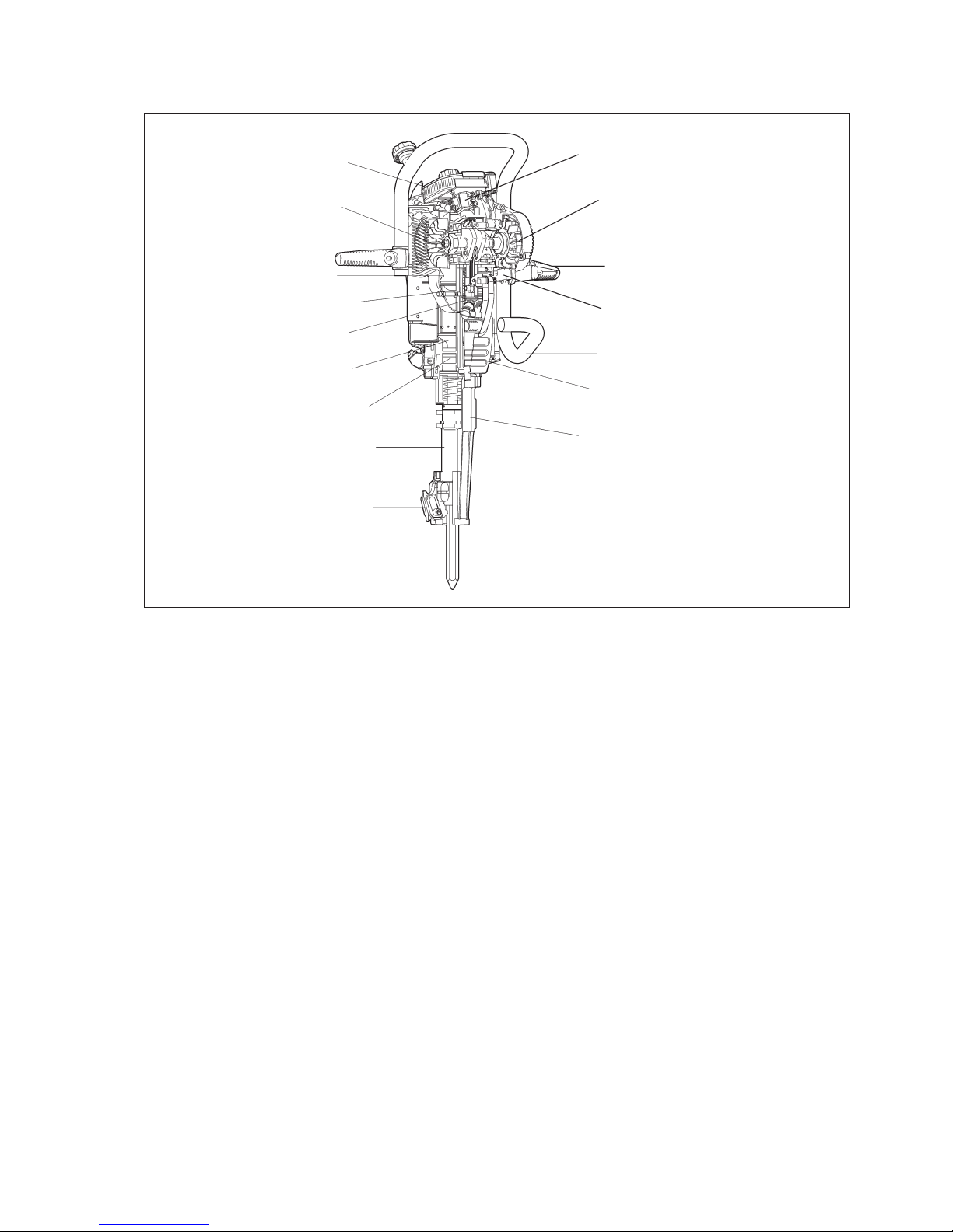
Design and function
Engine
The machine is powered by a single-cylinder,
air-cooled two-stroke engine. The engine is
equipped with a diaphragm carburettor, which is controlled by changes in pressure inside the crankcase.
The carburettor feeds the fuel mixture into the cylinder via a diaphragm valve. The engine is automatically lubricated by the oil in the fuel mixture.
The speed of the engine can be varied by the hand
throttle, which is connected to the carburettor butterfly valve.
The maximum speed of the engine is restricted by an
electronic speed restrictor, which is incorporated in
the breakerless ignition system.
The power transmission between the engine and
hammer mechanism is via a gear assembly.
Hammer mechanism
Before starting the engine, the hammer piston rests
on the tool shank. When the engine is started, the
drive piston commences to move up and down in the
hammer cylinder.
When the handles are pushed down, the tool raises
the hammer piston in the hammer cylinder and the
hammer mechanism is activated.
When the machine is lifted, the tool drops down onto
the tool latch. The hammer piston moves into its
lower position, where it stops, and the hammer
mechanism is disengaged.
This operational system also means that the machine can stand on a tool without engaging the hammer piston.
7
Air Filter
Cooling Fan
Drive piston
Decompression valve
Engine cylinder
Hammer piston
Hammer piston guide
Tool chuck
Tool latch
Carburettor
Starter mechanism
Throttle
Electronic unit
Fuel tank
Muffler
Tool holder
Crowder Supply Co., Inc. • 8495 Roslyn St., Commerce City, CO 80022 • Toll Free: 888-883-5144 • www.CrowderSupply.com
www.CrowderSupply.com • Toll Free: 888-883-5144
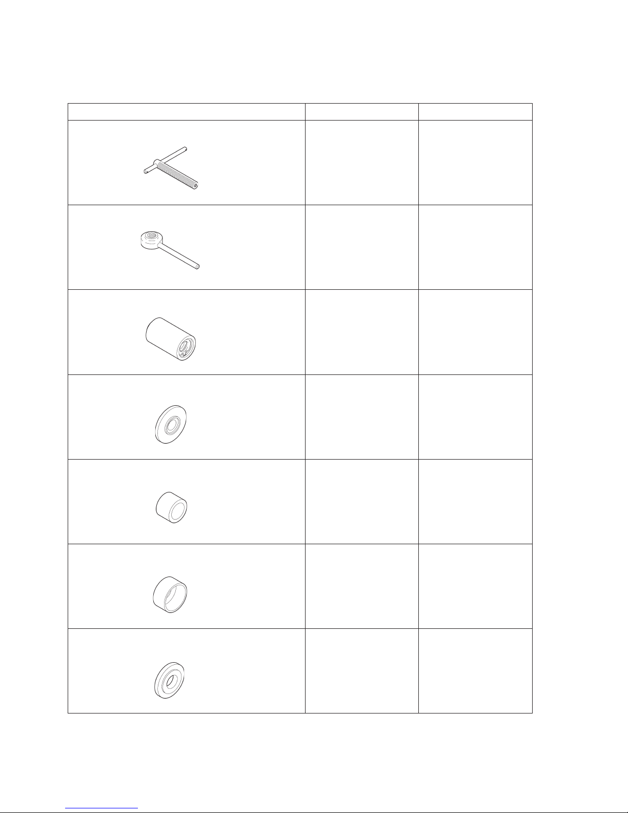
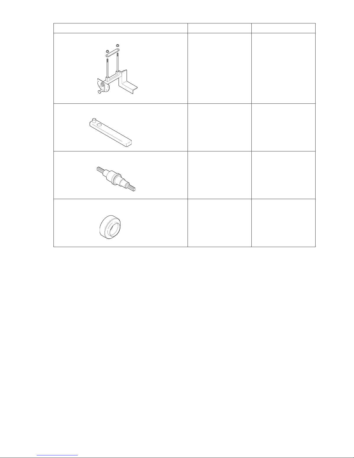
Service tools
(Complete set: order number 9234 0003 94)
Tool Order No. Designation
S1 9234 0003 58 Puller key
S2 9234 0003 59 Puller handle
S3 9234 0003 57 Puller sleeve
S4 9234 0003 71 Ring
S5 9234 0003 72 Ring
S6 9234 0003 68 Ring
S7 9234 0003 69 Ring
8
Crowder Supply Co., Inc. • 8495 Roslyn St., Commerce City, CO 80022 • Toll Free: 888-883-5144 • www.CrowderSupply.com
www.CrowderSupply.com • Toll Free: 888-883-5144
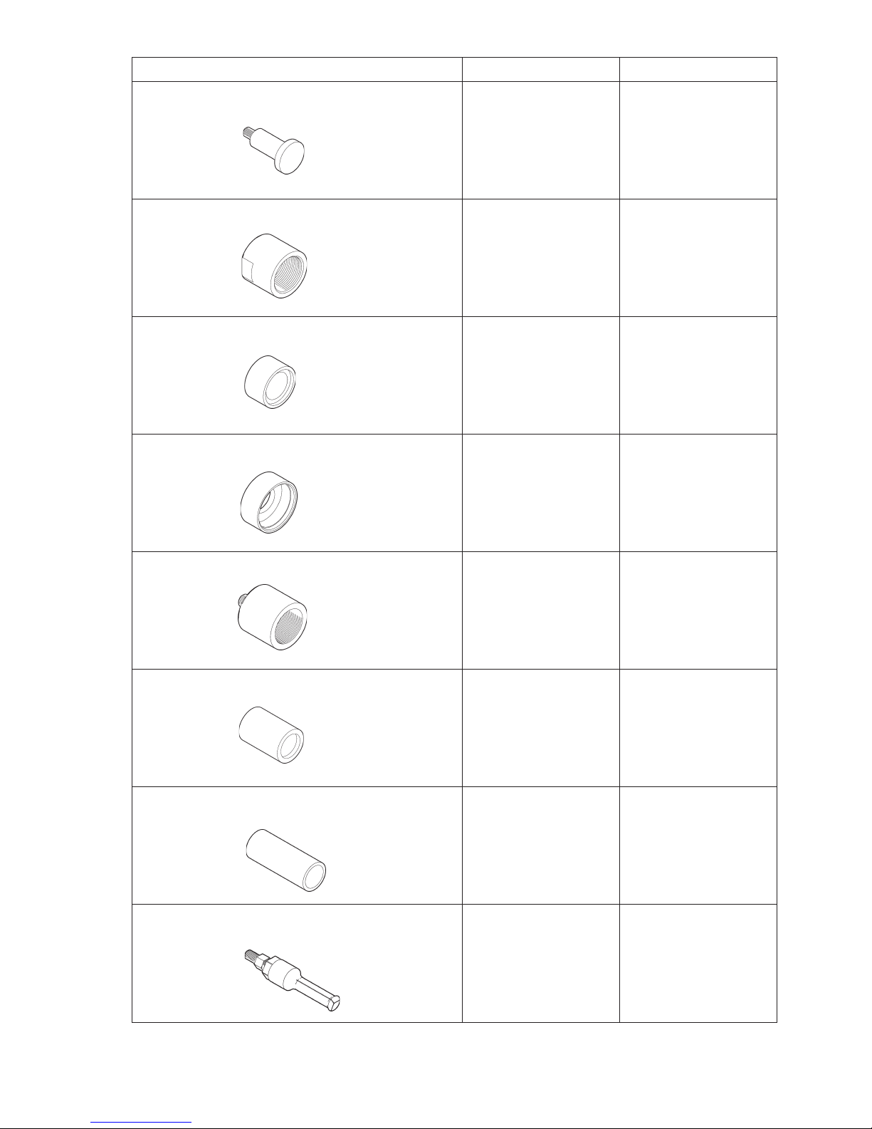
Tool Order No. Designation
S8 9234 0003 84 Tool
S9 9234 0003 83 Protective bush
S10 9234 0003 85 Ring
S11 9234 0003 70 Ring
S12 9234 0003 81 Tool
S13 9234 0003 74 Ring
S14 9234 0003 73 Ring
S15 9234 0003 93 Puller
9
Crowder Supply Co., Inc. • 8495 Roslyn St., Commerce City, CO 80022 • Toll Free: 888-883-5144 • www.CrowderSupply.com
www.CrowderSupply.com • Toll Free: 888-883-5144
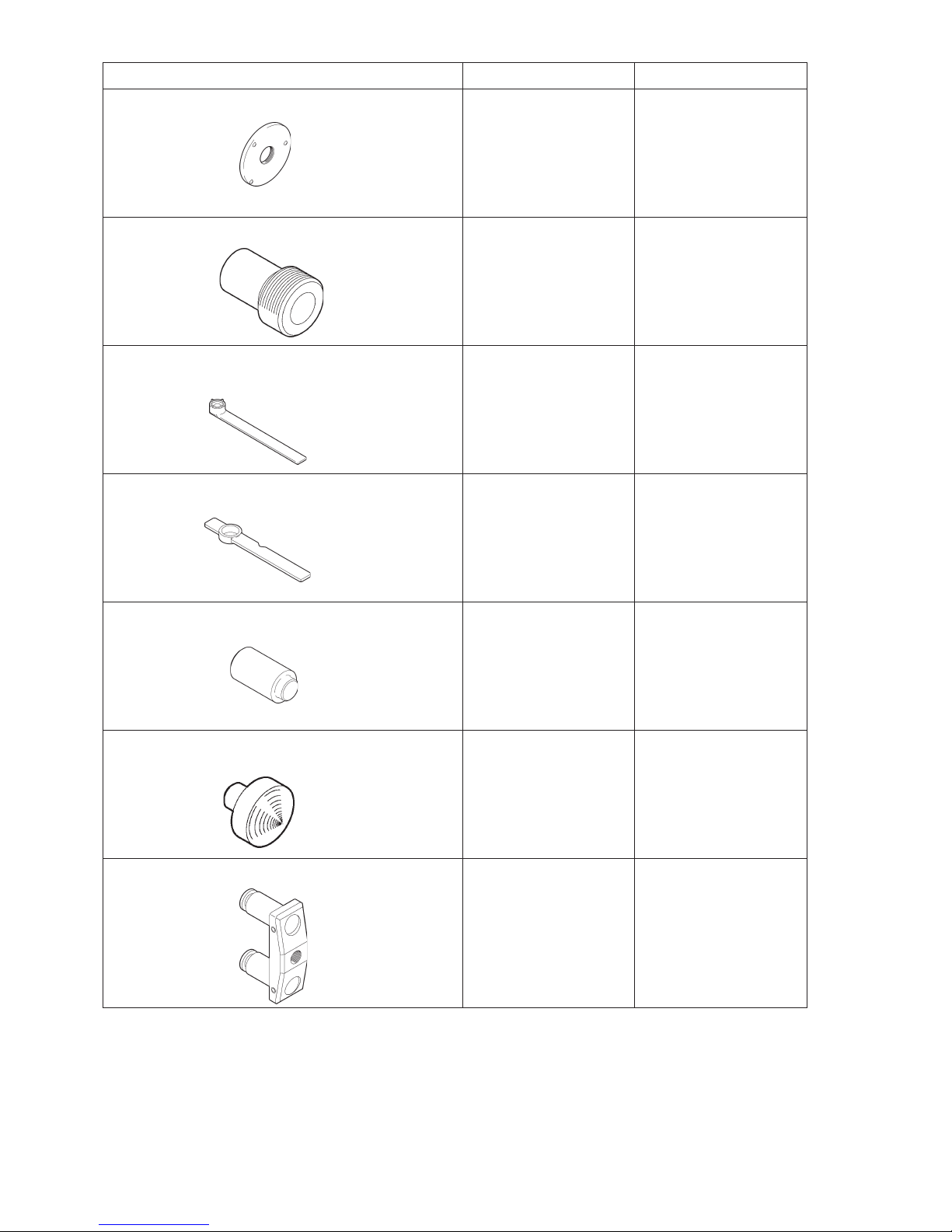
Tool Order No. Designation
S16 9234 0003 86 Ring
S17 9234 0003 80 Puller
S18 9234 0003 52 Tool
S19 9234 0003 49 Tool
S20 9234 0003 75 Tool
S21 9234 0003 82 Point
S22 9234 0003 53 Puller
10
Crowder Supply Co., Inc. • 8495 Roslyn St., Commerce City, CO 80022 • Toll Free: 888-883-5144 • www.CrowderSupply.com
www.CrowderSupply.com • Toll Free: 888-883-5144
Tool Order No. Designation
S23 9234 0003 66 Engine fixture
S24 9234 0003 51 Tool
S25 9234 0004 55 Tool
S26 9234 0004 57 Ring
11
Crowder Supply Co., Inc. • 8495 Roslyn St., Commerce City, CO 80022 • Toll Free: 888-883-5144 • www.CrowderSupply.com
www.CrowderSupply.com • Toll Free: 888-883-5144
Engine covers
Dismantling of the machine
General
Follow the instructions in this handbook carefully.
Use the tools listed under the heading ”Service tools”
on pages 9-12.
To avoid injury, always allow the machine to cool
down before service.
Always clean all loose dirt carefully from the machine
before servicing is carried out. Wash the parts in paraffin or a similar solvent. Do not use corrosive acids,
as this may cause damage to certain components.
Empty the fuel tank to prevent petrol from leaking
out.
Empty the oil from the hammer cylinder.
Remove the spark plug.
Spare part numbers are provided in a separate
spare parts list.
Use only Atlas Copco original spare parts.
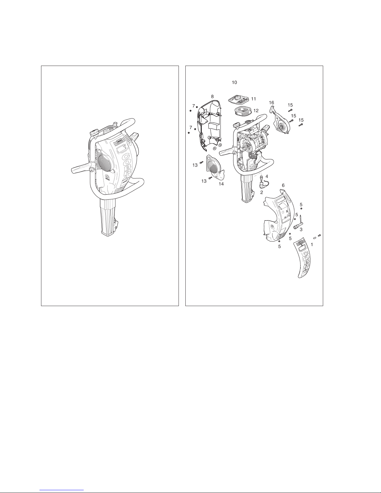
Dismantling of the covers
Service cover
Dismantle the service cover (1) from the machine.
Pull the ignition cable (2) from the spark plug (4) and
use the spark plug spanner (3) to remove the spark
plug.
Clean the electrodes with a steel brush and adjust
the electrode gap to 0.6-0.7 mm.
Note: To guarantee reliable starting and running, the
spark plug must be checked every week and replaced after 50 hammering hours.
Front cover
Remove the four nuts (5), push down the fuel tank,
and lift out the front cover (6).
Examine the cover for damage or cracks, and re
-
place if necessary.
12
Fig. 1 Fig. 2
Crowder Supply Co., Inc. • 8495 Roslyn St., Commerce City, CO 80022 • Toll Free: 888-883-5144 • www.CrowderSupply.com
www.CrowderSupply.com • Toll Free: 888-883-5144
 Loading...