

Atlas Copco CC234HF, CC334HF, CC2300, CC3300 Instruction Manual

Instruction manualInstruction manual
Operating & MaintenanceOperating & Maintenance
4812159801_A.pdf4812159801_A.pdf
Vibratory rollerVibratory roller
CC234HF/334HFCC234HF/334HF
CC2300/3300CC2300/3300
EngineEngine
Cummins QSB 3.3 (IIIA/T3)Cummins QSB 3.3 (IIIA/T3)
Deutz TCD 3.6 L04 (IIIB/T4i)Deutz TCD 3.6 L04 (IIIB/T4i)
Serial numberSerial number
10000313x0A009396 -10000313x0A009396 10000317x0A009737 -10000317x0A009737 10000338x0A011354 -10000338x0A011354 10000342x0A011649 -10000342x0A011649 -
Translation of original instructionTranslation of original instruction
Reservation for changesReservation for changes
Printed in SwedenPrinted in Sweden


4812159801_A.pdf2014-03-31
Table of Contents
Introduction .............................................................................................................................. 1
Warning symbols......................................................................................... 1
The machine ............................................................................................... 1
Intended use ............................................................................................... 1
Safety information ....................................................................................... 1
General ....................................................................................................... 2
CE marking and Declaration of conformity.................................................. 3
Safety - General instructions.................................................................................................... 5
Safety - when operating ........................................................................................................... 7
Slopes ......................................................................................................... 7
Driving near edges ...................................................................................... 8
Safety (Optional) ...................................................................................................................... 9
Air conditioning............................................................................................ 9
Edge cutter/compactor ................................................................................ 9
Working lights - Xenon .............................................................................. 10
Special instructions ................................................................................................................ 11
Standard lubricants and other recommended oils and fluids .................... 11
Higher ambient temperatures, above +40°C (104°F)................................ 11
Lower ambient temperature - Freeze risk ................................................. 11
Temperatures............................................................................................ 11
High pressure cleaning ............................................................................. 12
Fire fighting ............................................................................................... 12
Roll Over Protective Structure (ROPS), ROPS approved cab .................. 12
Battery handling ........................................................................................ 12
Jump starting (24V)................................................................................... 13
Technical specifications ......................................................................................................... 15
Vibrations - Operator station ..................................................................... 15
Noise level................................................................................................. 15
Electrical system ....................................................................................... 15
Dimensions, side view............................................................................... 16

4812159801_A.pdf 2014-03-31
Dimensions, top view ................................................................................ 17
Weights and volumes................................................................................ 18
Working capacity....................................................................................... 18
General ..................................................................................................... 19
Hydraulic system....................................................................................... 20
Automatic Climate Control (ACC) (Optional)............................................. 20
Tightening torque ...................................................................................... 21
Machine description ............................................................................................................... 23
Diesel engine ............................................................................................ 23
Electrical system ....................................................................................... 23
Propulsion system..................................................................................... 23
Brake system ............................................................................................ 24
Steering system ........................................................................................ 24
Vibration system........................................................................................ 24
Cab............................................................................................................ 24
ROPS ........................................................................................................ 24
Identification ............................................................................................................ 25
Product and component plates ................................................................. 25
Product identification number on the frame .............................................. 26
Machine plate............................................................................................ 26
Explanation of 17PIN serial number.......................................................... 26
Engine plates ............................................................................................ 27
Decals...................................................................................................................... 28
Location - decals ....................................................................................... 28
Safety decals............................................................................................. 29
Info decals................................................................................................. 31
Instruments/Controls ............................................................................................... 32
Control panel and controls ........................................................................ 32
Function descriptions ................................................................................ 33
Display explanations ................................................................................. 36

4812159801_A.pdf2014-03-31
Machine alarm........................................................................................... 40
"MAIN MENU" ........................................................................................... 41
"USER SETTINGS" .................................................................... 42
"MACHINE SETTINGS".............................................................. 43
"SERVICE MENU"...................................................................... 43
"ABOUT"..................................................................................... 45
Operator help when starting...................................................................... 45
Operator help Workmode.......................................................................... 45
Instruments and controls, cab ................................................................... 46
Function description of instruments and controls in the cab ..................... 47
Using the cab controls............................................................................... 48
Defroster ..................................................................................... 48
Heat ............................................................................................ 48
AC/ACC ...................................................................................... 48
Electrical system (version 1).................................................................................... 49
Fuse boxes in main switchbox .................................................................. 49
Electrical system (version 2).................................................................................... 50
Fuse card in main switchbox..................................................................... 50
Power in engine compartment/battery compartment ................................ 51
Main fuse panel (Cummins) ...................................................................... 51
Fuse box at master switch (Deutz)............................................................ 52
Fuses in cab.............................................................................................. 53
Operation ............................................................................................................................... 55
Before starting ......................................................................................................... 55
Master switch - Switching on..................................................................... 55
Control panel, adjustments ....................................................................... 55
Operator's seat - Adjustment..................................................................... 56
Operator's seat, comfort - Adjustments..................................................... 56
Parking brake ............................................................................................ 57
Display - Control........................................................................................ 57

4812159801_A.pdf 2014-03-31
Interlock..................................................................................................... 58
Operator position....................................................................................... 59
View .......................................................................................................... 59
Starting .................................................................................................................... 60
Starting the engine .................................................................................... 60
Display when activating choice via the button set..................................... 61
Alarm descriptions..................................................................................... 62
Driving ..................................................................................................................... 63
Operating the roller ................................................................................... 63
Machine with gear change in separate spring-return switch
(gear position switch).................................................................. 63
Interlock/Emergency stop/Parking brake - Check ..................................... 65
Pivotal steering (Optional)......................................................................... 66
Edge cutting (Optional) ............................................................................. 66
Vibration .................................................................................................................. 67
Manual/Automatic vibration....................................................................... 67
Manual vibration - Switching on ................................................................ 68
Amplitude/frequency - Changeover........................................................... 68
Braking .................................................................................................................... 68
Normal braking.......................................................................................... 68
Emergency braking ................................................................................... 69
Switching off.............................................................................................. 69
Parking .................................................................................................................... 70
Chocking the drums .................................................................................. 70
Master switch ............................................................................................ 70
Long-term parking.................................................................................................................. 71
Engine ....................................................................................................... 71
Battery....................................................................................................... 71
Air cleaner, exhaust pipe........................................................................... 71
Watering system ....................................................................................... 71

4812159801_A.pdf2014-03-31
Fuel tank ................................................................................................... 71
Hydraulic reservoir .................................................................................... 71
Hoods, tarpaulin ........................................................................................ 72
Steering cylinder, hinges, etc. ................................................................... 72
Miscellaneous ........................................................................................................................ 73
Lifting ....................................................................................................................... 73
Locking the articulation ............................................................................. 73
Lifting the roller.......................................................................................... 74
Lifting the roller with jack:.......................................................................... 74
Unlocking the articulation .......................................................................... 75
Towing/Recovering.................................................................................................. 75
Short distance towing with the engine running.......................................... 76
Short distance towing when the engine is inoperative. ............................. 76
Towing the roller........................................................................................ 77
Trailer eye ................................................................................................. 77
Transport ................................................................................................................. 78
Loading CC224-624HF, CC2200-6200..................................................... 79
Operating instructions - Summary ......................................................................................... 81
Preventive maintenance ........................................................................................................ 83
Acceptance and delivery inspection.......................................................... 83
Warranty.................................................................................................... 83
Maintenance - Lubricants and symbols ................................................................................. 85
Maintenance symbols ............................................................................... 86
Maintenance - Maintenance schedule ................................................................................... 87
Service and maintenance points ............................................................... 87
General ..................................................................................................... 87
Every 10 hours of operation (Daily)........................................................... 88
After the FIRST 50 hours of operation ...................................................... 88
Every 50 hours of operation (Weekly)....................................................... 89
Every 250 hours of operation (Monthly) .................................................... 89

4812159801_A.pdf 2014-03-31
Every 500/1500 hours of operation ........................................................... 90
Every 1000 hours of operation .................................................................. 91
Every 2000 hours of operation .................................................................. 92
Maintenance, 10h .................................................................................................................. 93
Diesel engine - Check oil level .................................................................. 93
Coolant level - Check ................................................................................ 94
Fuel tank - Refueling ................................................................................. 94
Water tank, Std - Filling............................................................................. 95
Hydraulic reservoir - Check fluid level....................................................... 95
Sprinkler system/Drum
Check ........................................................................................................ 96
Cleaning the coarse filter .......................................................................... 96
Sprinkler system/Drum
Cleaning of sprinkler nozzle ...................................................................... 97
Emergency watering (Accessory) - Extra pump in pump system.............. 97
Scrapers, spring-action
Check ........................................................................................................ 98
Scrapers
Setting - Adjustment.................................................................................. 98
Maintenance - 50h ............................................................................................................... 101
Fuel filter - Draining................................................................................. 101
Drum gearbox - Checking the oil level .................................................... 102
Maintenance - 250 / 750 / 1250 / 1750h .............................................................................. 103
Diesel engine
Oil change ............................................................................................... 103
Engine
Replacing oil filter.................................................................................... 104
Hydraulic fluid cooler
Checking - Cleaning................................................................................ 104
Battery
- Check condition .................................................................................... 105
Air conditioning (Optional)
- Inspection.............................................................................................. 105

4812159801_A.pdf2014-03-31
Air conditioning (Optional)
Drying filter - Inspection .......................................................................... 106
Edge cutter (Optional)
- Lubrication ............................................................................................ 106
Maintenance - 500 / 1500h .................................................................................................. 107
Diesel engine
Oil change ............................................................................................... 107
Engine
Replacing oil filter.................................................................................... 108
The engine fuel filter - replacement/cleaning .......................................... 108
Hydraulic fluid cooler
Checking - Cleaning................................................................................ 109
Battery
- Check condition .................................................................................... 109
Air cleaner
Checking - Change the main air filter...................................................... 110
Backup filter - Change............................................................................. 110
Air cleaner
- Cleaning................................................................................................ 111
Drum - oil level
Inspection - filling .................................................................................... 112
Hydraulic reservoir cap - Check .............................................................. 112
Rubber elements and attachment screws
Check ...................................................................................................... 113
Seat bearing - Lubrication ....................................................................... 113
Pivot bearing (Optional) - Lubrication...................................................... 114
Air conditioning (Optional)
- Inspection.............................................................................................. 114
Air conditioning (Optional)
Drying filter - Inspection .......................................................................... 115
Edge cutter (Optional)
- Lubrication ............................................................................................ 115
Maintenance - 1000h ........................................................................................................... 117
Diesel engine
Oil change ............................................................................................... 117

4812159801_A.pdf 2014-03-31
Engine
Replacing oil filter.................................................................................... 118
The engine fuel filter - replacement/cleaning .......................................... 118
Hydraulic fluid cooler
Checking - Cleaning................................................................................ 119
Air cleaner
Checking - Change the main air filter...................................................... 119
Backup filter - Change............................................................................. 120
Air cleaner
- Cleaning................................................................................................ 120
Battery
- Check condition .................................................................................... 121
Hydraulic filter
Change.................................................................................................... 121
Hydraulic reservoir cap - Check .............................................................. 122
Drum - Changing the oil .......................................................................... 123
Drum gearbox - Oil change ..................................................................... 123
Rubber elements and attachment screws
Check ...................................................................................................... 124
Seat bearing - Lubrication ....................................................................... 124
Pivot bearing (Optional) - Lubrication...................................................... 125
Cab
Fresh air filter - Replacing ....................................................................... 125
Air conditioning (Optional)
- Overhaul ............................................................................................... 126
Air conditioning (Optional)
Drying filter - Inspection .......................................................................... 126
Edge cutter (Optional)
- Lubrication ............................................................................................ 127
Steering hitch - Tightening ...................................................................... 127
Maintenance - 2000h ........................................................................................................... 129
Diesel engine
Oil change ............................................................................................... 129
Engine
Replacing oil filter.................................................................................... 130

4812159801_A.pdf2014-03-31
The engine fuel filter - replacement/cleaning .......................................... 130
Hydraulic fluid cooler
Checking - Cleaning................................................................................ 131
Air cleaner
Checking - Change the main air filter...................................................... 131
Backup filter - Change............................................................................. 132
Air cleaner
- Cleaning................................................................................................ 132
Battery
- Check condition .................................................................................... 133
Hydraulic filter
Change.................................................................................................... 133
Drum - Changing the oil .......................................................................... 134
Drum gearbox - Oil change ..................................................................... 135
Rubber elements and attachment screws
Check ...................................................................................................... 135
Seat bearing - Lubrication ....................................................................... 136
Hydraulic reservoir cap - Check .............................................................. 136
Hydraulic reservoir
Fluid change............................................................................................ 137
Fuel tank
- Cleaning............................................................................................... 137
Watering system
- Draining................................................................................................ 138
Water tank - Cleaning ............................................................................. 138
Steering joint - Check.............................................................................. 139
Pivot bearing (Optional) - Lubrication...................................................... 139
Cab
Fresh air filter - Replacing ....................................................................... 139
Air conditioning (Optional)
- Overhaul ............................................................................................... 140
Air conditioning (Optional)
Drying filter - Inspection .......................................................................... 140
Edge cutter (Optional)
- Lubrication ............................................................................................ 141

4812159801_A.pdf 2014-03-31
Steering hitch - Tightening ...................................................................... 141

Introduction
4812159801_A.pdf2014-03-31
Introduction
Warning symbols
The machine
Dynapac CC234HF/334HF, CC2300/3300 is a
self-propelled vibratory tandem roller in 8/9 metric
tonnes class featuring 1500/1730 mm (59/68 in) wide
split drums. The machine is equipped with drive,
brakes, vibration and timer for water sprinkler on both
drums. Propulsion and braking are applied to all drum
halves.
CC234HF/334HF, CC2300/3300 is also available as
Combi with four rubber wheels at rear replacing the
split steel drum.
A variety of different engine power settings, operator
platforms, control possibilities and options makes the
machine available in a lot of different configurations.
Intended use
The machines is mainly designed to be used for thin
and thick asphalt layers with regards to dual vibration
amplitudes that are optimized for this purpose. It is
also possible to compact granular soil material, such
as sand and gravel.
WARNING ! Marks a danger or a hazardous
procedure that can result in life threatening or
serious injury if the warning is ignored.
WARNING ! Marks a danger or a hazardous
procedure that can result in life threatening or
serious injury if the warning is ignored.
CAUTION ! Marks a danger or hazardous
procedure that can result in damage to the
machine or property if the warning is ignored.
CAUTION ! Marks a danger or hazardous
procedure that can result in damage to the
machine or property if the warning is ignored.
Safety information
It is recommended to at least train operators in
handling and daily maintenance of the machine
in accordance with the instruction manual.
It is recommended to at least train operators in
handling and daily maintenance of the machine
in accordance with the instruction manual.
Passengers are not allowed on the machine, and
you must sit in the seat when operating the
machine.
Passengers are not allowed on the machine, and
you must sit in the seat when operating the
machine.
The safety manual supplied with the machine
must be read by all roller operators. Always
follow the safety instructions. Do not remove
the manual from the machine.
The safety manual supplied with the machine
must be read by all roller operators. Always
follow the safety instructions. Do not remove
the manual from the machine.
1

Introduction
4812159801_A.pdf 2014-03-31
We recommend that the operator reads the
safety instructions in this manual carefully.
Always follow the safety instructions. Ensure
that this manual is always easily accessible.
We recommend that the operator reads the
safety instructions in this manual carefully.
Always follow the safety instructions. Ensure
that this manual is always easily accessible.
Read the entire manual before starting the
machine and before carrying out any
maintenance.
Read the entire manual before starting the
machine and before carrying out any
maintenance.
Replace immediately the instruction manuals if
lost, damaged or unreadable.
Replace immediately the instruction manuals if
lost, damaged or unreadable.
Ensure good ventilation (extraction of air by fan)
where the engine is run indoors.
Ensure good ventilation (extraction of air by fan)
where the engine is run indoors.
CALIFORNIA
Proposition 65 Warning
Diesel engine exhaust and some of its constituents are
known to the State of California to cause cancer, birth
defects, and other reproductive harm.
General
This manual contains instructions for machine
operation and maintenance.
The machine must be correctly maintained for
maximal performance.
The machine should be kept clean so that any
leakages, loose bolts and loose connections are
discovered at as early a point in time as possible.
Inspect the machine every day, before starting.
Inspect the entire machine so that any leakages or
other faults are detected.
Check the ground under the machine. Leakages are
more easily detected on the ground than on the
machine itself.
THINK ENVIRONMENT ! Do not release oil,
fuel and other environmentally hazardous
substances into the environment. Always send
used filters, drain oil and fuel remnants to
environmentally correct disposal.
THINK ENVIRONMENT ! Do not release oil,
fuel and other environmentally hazardous
substances into the environment. Always send
used filters, drain oil and fuel remnants to
environmentally correct disposal.
2

Introduction
4812159801_A.pdf2014-03-31
This manual contains instructions for periodic
maintenance normally carried out by the operator.
Additional instructions for the engine can be
found in the manufactuer's engine manual.
Additional instructions for the engine can be
found in the manufactuer's engine manual.
CE marking and Declaration of conformity
(Applies to machines marketed in EU/EEC)
This machine is CE marked. This shows that on
delivery it complies with the basic health and safety
directives applicable for the machine in accordance
with machinery directive 2006/42/EC and that it also
complies with other directives applicable for this
machine.
A "Declaration of conformity" is supplied with this
machine, which specifies the applicable directives and
supplements, as well as the harmonized standards
and other regulations that are applied.
3

Introduction
4812159801_A.pdf 2014-03-31
4

Safety - General instructions
4812159801_A.pdf2014-03-31
Safety - General instructions
(Also read the safety manual)
1. The operator must be familiar with the contents of the OPERATION section
before starting the roller.
1. The operator must be familiar with the contents of the OPERATION section
before starting the roller.
2. Ensure that all instructions in the MAINTENANCE section are followed.2. Ensure that all instructions in the MAINTENANCE section are followed.
3. Only trained and/or experienced operators are to operate the roller.
Passengers are not permitted on the roller. Remain seated at all times when
operating the roller.
3. Only trained and/or experienced operators are to operate the roller.
Passengers are not permitted on the roller. Remain seated at all times when
operating the roller.
4. Never use the roller if it is in need of adjustment or repair.4. Never use the roller if it is in need of adjustment or repair.
5. Only mount and dismount the roller when it is stationary. Use the intended
grips and rails. Always use the three-point grip (both feet and one hand, or
one foot and both hands) when mounting or dismounting the machine.
Never jump down from the machine.
5. Only mount and dismount the roller when it is stationary. Use the intended
grips and rails. Always use the three-point grip (both feet and one hand, or
one foot and both hands) when mounting or dismounting the machine.
Never jump down from the machine.
6. The ROPS (Roll Over Protective Structure) should always be used when the
machine is operated on unsafe ground.
6. The ROPS (Roll Over Protective Structure) should always be used when the
machine is operated on unsafe ground.
7. Drive slowly in sharp bends.7. Drive slowly in sharp bends.
8. Avoid driving across slopes. Drive straight up or straight down the slope.8. Avoid driving across slopes. Drive straight up or straight down the slope.
9. When driving close to edges, ditches or holes, make sure that at least 2/3 of
the drum width is on previously compacted material (solid surface).
9. When driving close to edges, ditches or holes, make sure that at least 2/3 of
the drum width is on previously compacted material (solid surface).
10. Make sure that there are no obstacles in the direction of travel, on the
ground, in front of or behind the roller, or overhead.
10. Make sure that there are no obstacles in the direction of travel, on the
ground, in front of or behind the roller, or overhead.
11. Drive particularly carefully on uneven ground.11. Drive particularly carefully on uneven ground.
12. Use the safety equipment provided. The seat belt must be worn on machines
fitted with ROPS/ROPS-cab.
12. Use the safety equipment provided. The seat belt must be worn on machines
fitted with ROPS/ROPS-cab.
13. Keep the roller clean. Clean any dirt or grease that accumulates on the
operator platform immediately. Keep all signs and decals clean and legible.
13. Keep the roller clean. Clean any dirt or grease that accumulates on the
operator platform immediately. Keep all signs and decals clean and legible.
14. Safety measures before refueling:
- Stop the engine
- Do not smoke.
- No naked flames in the vicinity of the roller.
- Earth the filling equipment nozzle to the tank opening to avoid sparks.
14. Safety measures before refueling:
- Stop the engine
- Do not smoke.
- No naked flames in the vicinity of the roller.
- Earth the filling equipment nozzle to the tank opening to avoid sparks.
15. Before repairs or service:
- Chock the drums/wheels and under the strike-off blade.
- Lock the articulation if necessary
15. Before repairs or service:
- Chock the drums/wheels and under the strike-off blade.
- Lock the articulation if necessary
5

Safety - General instructions
4812159801_A.pdf 2014-03-31
16. Hearing protection is recommended if the noise level exceeds 85 dB(A). The
noise level can vary depending on the equipment on the machine and the
surface the machine is being used on.
16. Hearing protection is recommended if the noise level exceeds 85 dB(A). The
noise level can vary depending on the equipment on the machine and the
surface the machine is being used on.
17. Do not make any changes or modifications to the roller that could affect
safety. Changes are only to be made after written approval has been given
by Dynapac.
17. Do not make any changes or modifications to the roller that could affect
safety. Changes are only to be made after written approval has been given
by Dynapac.
18. Avoid using the roller before the hydraulic fluid has reached its normal
working temperature. Braking distances can be longer than normal when the
fluid is cold. See instructions in the STOP section.
18. Avoid using the roller before the hydraulic fluid has reached its normal
working temperature. Braking distances can be longer than normal when the
fluid is cold. See instructions in the STOP section.
19. For your own protection always wear:
- helmet
- working boots with steel toecaps
- ear protectors
- reflecting clothing/high visibility jacket
- working gloves
19. For your own protection always wear:
- helmet
- working boots with steel toecaps
- ear protectors
- reflecting clothing/high visibility jacket
- working gloves
6
Safety - when operating
4812159801_A.pdf2014-03-31
Safety - when operating
Prevent persons from entering or remaining in
the danger area, i.e. a distance of at least 7 m
(23 ft) in all directions from operating machines.
Prevent persons from entering or remaining in
the danger area, i.e. a distance of at least 7 m
(23 ft) in all directions from operating machines.
The operator may allow a person to remain in
the danger area, but should then observe
caution and operate the machine only when the
person is visible or has given clear indications
of where he or she is.
The operator may allow a person to remain in
the danger area, but should then observe
caution and operate the machine only when the
person is visible or has given clear indications
of where he or she is.
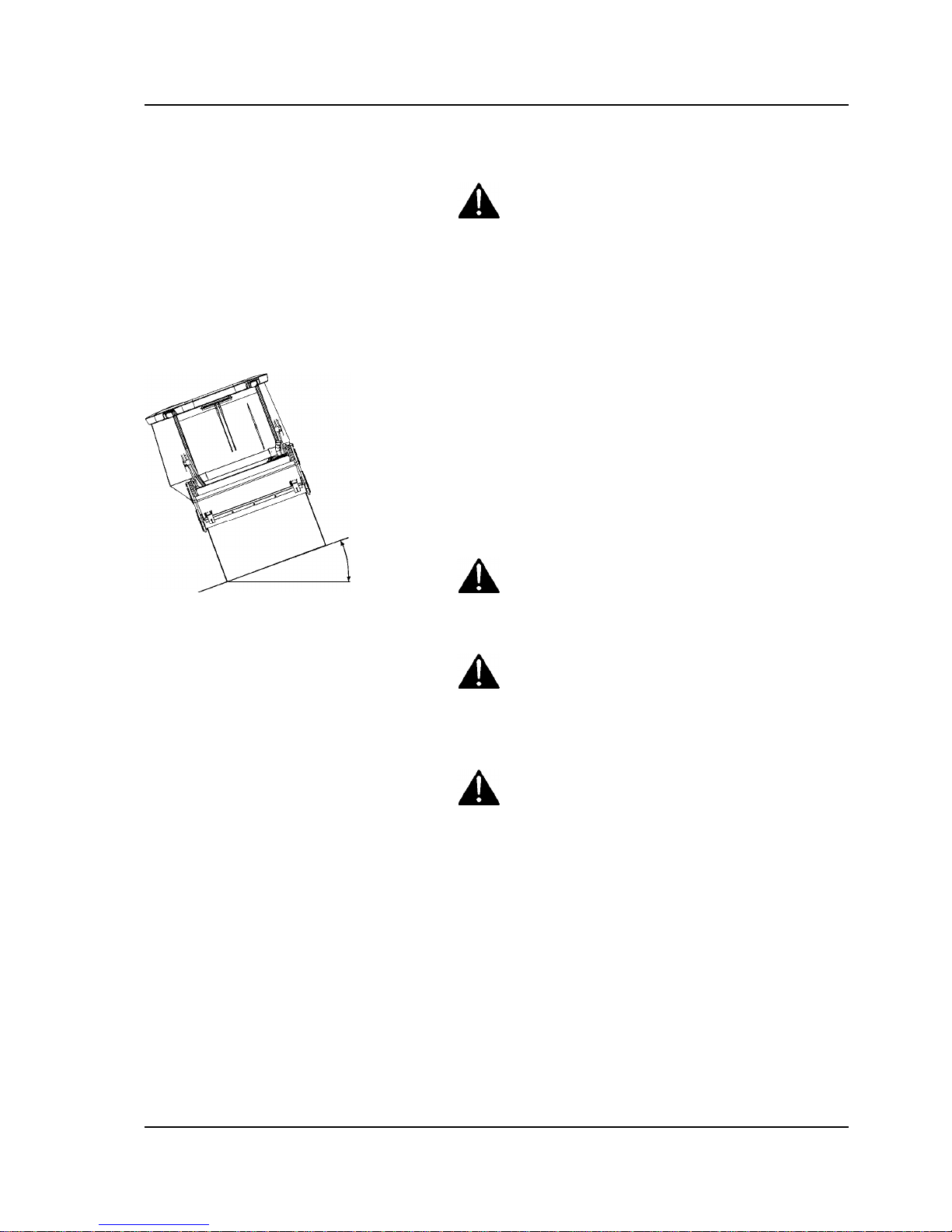
Slopes
Fig. Operating on slopes
Max 20° or 36%
This angle has been measured on a hard, flat surface
with the machine stationary.
The steering angle was zero, the vibration was
switched OFF and all tanks were full.
Always take into consideration that loose ground,
steering the machine, vibration on, machine speed
across the ground and raising the center of gravity can
all cause the machine to topple at smaller slope
angles than those specified here.
To exit the cab in an emergency, release the
hammer on the rear right post and break the right
opening side-windows.
To exit the cab in an emergency, release the
hammer on the rear right post and break the right
opening side-windows.
It is recommended that ROPS (Roll Over Protective
Structure) or a ROPS approved cab, is always
used when driving on slopes or unsafe ground.
It is recommended that ROPS (Roll Over Protective
Structure) or a ROPS approved cab, is always
used when driving on slopes or unsafe ground.
Where possible, avoid driving across slopes.
Drive instead straight up and down sloping
ground.
Where possible, avoid driving across slopes.
Drive instead straight up and down sloping
ground.
7
Safety - when operating
4812159801_A.pdf 2014-03-31
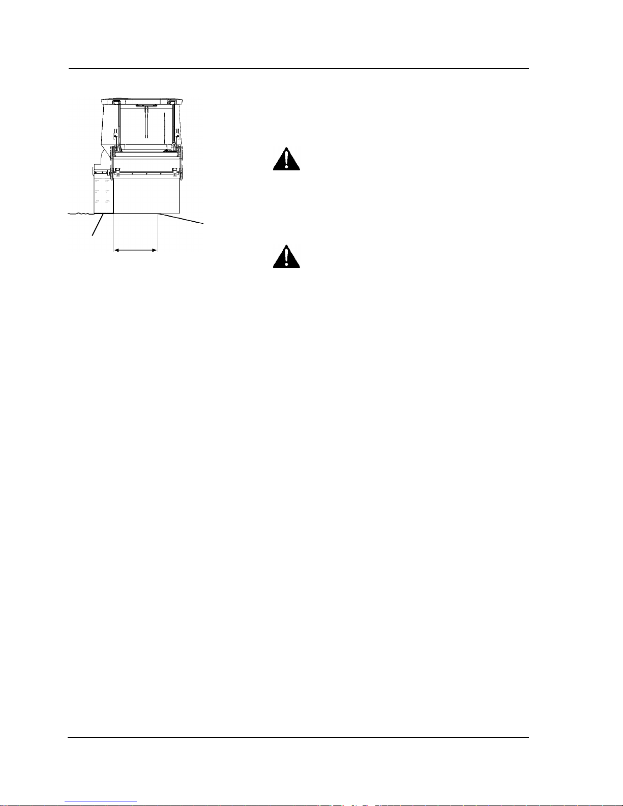
Driving near edges
Fig. Position of drums when driving
near an edge
1. Pivotal steering
1
≥ 2/3
When driving near an edge, minimum 2/3 of the drum
width must be on solid ground.
When using pivotal steering, only one drum
should be allowed to move into the position
shown in the picture. The other drum must be in
contact with the ground across its full width.
When using pivotal steering, only one drum
should be allowed to move into the position
shown in the picture. The other drum must be in
contact with the ground across its full width.
Keep in mind that the machine's center of
gravity moves outwards when steering. For
example, the center of gravity moves to the right
when you steer to the left.
Keep in mind that the machine's center of
gravity moves outwards when steering. For
example, the center of gravity moves to the right
when you steer to the left.
8
Safety (Optional)
4812159801_A.pdf2014-03-31
Safety (Optional)
Air conditioning
The system contains pressurized refrigerant. It is
forbidden to release refrigerants into the
atmosphere.
The system contains pressurized refrigerant. It is
forbidden to release refrigerants into the
atmosphere.
Fig. Air conditioning (ACC)
Work on the refrigerant circuit is only to be carried
out by authorized companies.
Work on the refrigerant circuit is only to be carried
out by authorized companies.
The cooling system is pressurized. Incorrect
handling can result in serious personal injury. Do
not disconnect or undo the hose couplings.
The cooling system is pressurized. Incorrect
handling can result in serious personal injury. Do
not disconnect or undo the hose couplings.
The system must be re-filled with an approved
refrigerant by authorized personnel when
necessary. See decal on or in the vicinity of the
installation.
The system must be re-filled with an approved
refrigerant by authorized personnel when
necessary. See decal on or in the vicinity of the
installation.
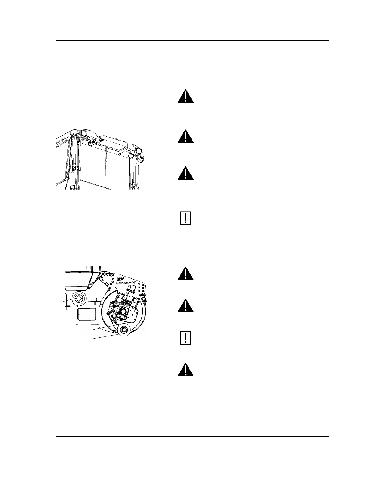
Edge cutter/compactor
Fig. Edge cutter/compactor
1. Transport position
2. Operating position
3. Holder for cutter/compactor wheel.
3
1
2
The operator must make sure that nobody is in the
area of operation while the machine is in use.
The operator must make sure that nobody is in the
area of operation while the machine is in use.
The edge cutter consists of rotating components
and there is a risk of being crushed.
The edge cutter consists of rotating components
and there is a risk of being crushed.
The tool must be returned to the transport
position (raised position) (1) every time it has
been used.
The tool must be returned to the transport
position (raised position) (1) every time it has
been used.
If the edge cutter and its parts are dismantled,
make sure that it is set in a relieved position and
resting on the ground.
If the edge cutter and its parts are dismantled,
make sure that it is set in a relieved position and
resting on the ground.
9
Safety (Optional)
4812159801_A.pdf 2014-03-31
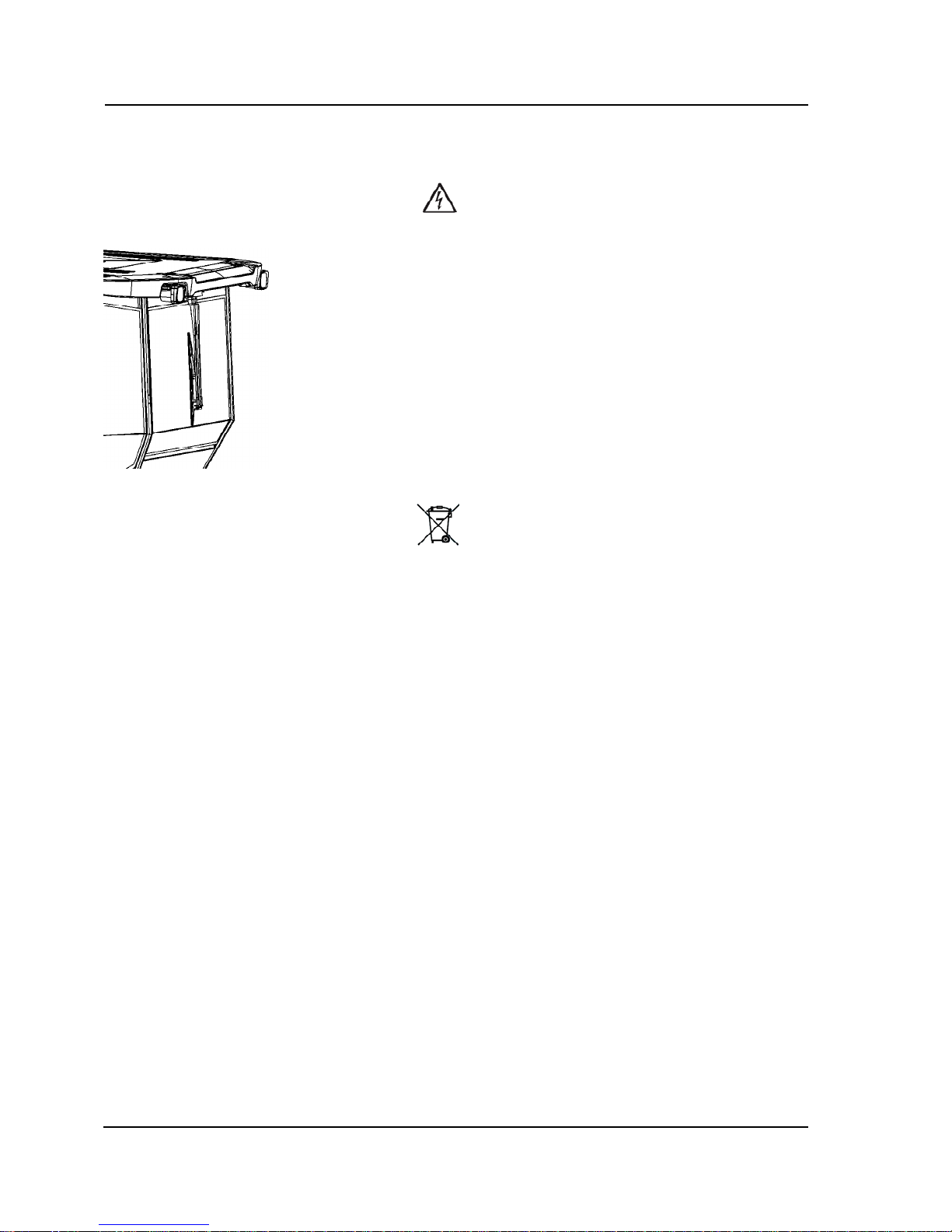
Working lights - Xenon
Warning, high voltage!Warning, high voltage!
Figure. Xenon lighting on cab
The working lights of the Xenon type have a
secondary high-voltage source.
Work on the lighting should only be conducted by an
authorized electrician and with the primary voltage
disconnected.
Contact a Dynapac dealer!
Warning, environmentally hazardous waste!Warning, environmentally hazardous waste!
Working lights of the Xenon type include a discharge
lamp that contains mercury (Hg).
A defective lamp is to be considered as hazardous
waste and shall be disposed off as per local directives.
10

Special instructions
4812159801_A.pdf2014-03-31
Special instructions
Standard lubricants and other recommended
oils and fluids
Before leaving the factory, the systems and
components are filled with the oils and fluids specified
in the lubricant specification. These are suitable for
ambient temperatures in the range -15°C to +40°C
(5°F - 105°F).
The maximum temperature for biological
hydraulic fluid is +35°C (95°F).
The maximum temperature for biological
hydraulic fluid is +35°C (95°F).
Higher ambient temperatures, above +40°C
(104°F)
For operation of the machine at higher ambient
temperatures, however maximum +50°C (122°F), the
following recommendations apply:
The diesel engine can be run at this temperature using
normal oil. However, the following fluids must be used
for other components:
Hydraulic system - mineral oil Shell Tellus S2V100 or
similar.
Lower ambient temperature - Freeze risk
Make sure that the watering system is empty/drained
of water (sprinkler, hoses, tank/s) or that anti-freeze
has been added, to prevent the system freezing.
The outlet hose from the central tank can be
disconnected and the end placed in a container with
antifreeze to run this through the pump/filter.
Temperatures
The temperature limits apply to standard versions of
rollers.
Rollers equipped with additional equipment, such as
noise suppression, may need to be more carefully
monitored in the higher temperature ranges.
11

Special instructions
4812159801_A.pdf 2014-03-31
High pressure cleaning
Do not spray directly onto electrical components.
Do not use high pressure cleaning for
dashboard/display.
Do not use high pressure cleaning for
dashboard/display.
The Electrical Drive Control and the computer
box may not be washed with high pressure
cleaning and not at all with water. Clean them
with a dry wiper.
The Electrical Drive Control and the computer
box may not be washed with high pressure
cleaning and not at all with water. Clean them
with a dry wiper.
Detergent that can destroy electrical parts, or
which is conductive, must not be used.
Detergent that can destroy electrical parts, or
which is conductive, must not be used.
Place a plastic bag over the fuel filler cap and secure
with a rubber band. This is to avoid high pressure
water entering the vent hole in the filler cap. This could
cause malfunctions, such as the blocking of filters.
Never aim the water jet directly at the fuel tank
cap. This is particularly important when using a
high-pressure cleaner.
Never aim the water jet directly at the fuel tank
cap. This is particularly important when using a
high-pressure cleaner.
Fire fighting
If the machine catches fire, use an ABC-class powder
fire extinguisher.
A BE-class carbon dioxide fire extinguisher can also
be used.
Roll Over Protective Structure (ROPS), ROPS
approved cab
If the machine is fitted with a Roll Over
Protective Structure (ROPS, or ROPS approved
cab) never carry out any welding or drilling in
the structure or cab.
If the machine is fitted with a Roll Over
Protective Structure (ROPS, or ROPS approved
cab) never carry out any welding or drilling in
the structure or cab.
Never attempt to repair a damaged ROPS
structure or cab. These must be replaced with
new ROPS structure or cabs.
Never attempt to repair a damaged ROPS
structure or cab. These must be replaced with
new ROPS structure or cabs.
Battery handling
When removing batteries, always disconnect the
negative cable first.
When removing batteries, always disconnect the
negative cable first.
12
Special instructions
4812159801_A.pdf2014-03-31
When fitting batteries, always connect the
positive cable first.
When fitting batteries, always connect the
positive cable first.
Dispose of old batteries in an environmentally
friendly way. Batteries contain toxic lead.
Dispose of old batteries in an environmentally
friendly way. Batteries contain toxic lead.
Do not use a quick-charger for charging the
battery. This may shorten battery life.
Do not use a quick-charger for charging the
battery. This may shorten battery life.
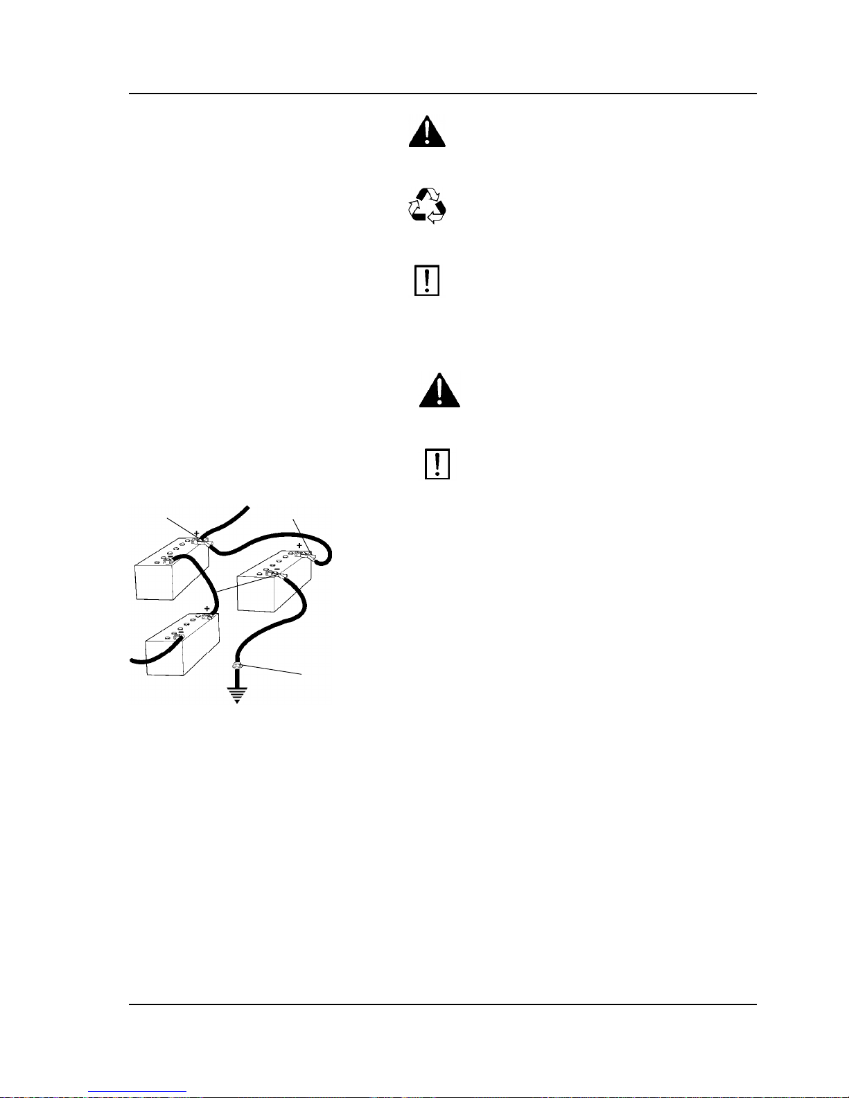
Jump starting (24V)
Do not connect the negative cable to the
negative terminal on the dead battery. A spark
can ignite the oxy-hydrogen gas formed
around the battery.
Do not connect the negative cable to the
negative terminal on the dead battery. A spark
can ignite the oxy-hydrogen gas formed
around the battery.
Check that the battery used for jump starting
has the same voltage as the dead battery.
Check that the battery used for jump starting
has the same voltage as the dead battery.
24V
12V
12V
Fig. Jump starting
1
2
3
4
Turn the ignition and all power consuming equipment
off. Switch off the engine on the machine which is
providing jump start power.
Jump leads must have 24V.
First connect the jump start battery's positive terminal
(1) to the flat battery's positive terminal (2).Then
connect the jump start battery's negative terminal (3)
to, for example, a bolt (4) or the lifjting eye on the
machine with the flat battery.
Start the engine on the power providing machine. Let it
run for a while. Now try to start the other machine.
Disconnect the cables in the reverse order.
13

Special instructions
4812159801_A.pdf 2014-03-31
14

Technical specifications
4812159801_A.pdf2014-03-31
Technical specifications
Vibrations - Operator station
(ISO 2631)
The vibration levels are measured in accordance with the operational cycle described in
EU directive 2000/14/EC on machines equipped for the EU market, with vibration switched
on, on soft polymer material and with the operator’s seat in the transport position.
The vibration levels are measured in accordance with the operational cycle described in
EU directive 2000/14/EC on machines equipped for the EU market, with vibration switched
on, on soft polymer material and with the operator’s seat in the transport position.
Measured whole-body vibrations are below the action value of 0.5 m/s² as specified in Directive
2002/44/EC. (Limit is 1.15 m/s²)
Measured whole-body vibrations are below the action value of 0.5 m/s² as specified in Directive
2002/44/EC. (Limit is 1.15 m/s²)
Measured hand/arm vibrations also were below the action level of 2.5 m/s² specified in the same
directive. (Limit is 5 m/s²)
Measured hand/arm vibrations also were below the action level of 2.5 m/s² specified in the same
directive. (Limit is 5 m/s²)
Noise level
The noise level is measured in accordance with the operational cycle described in
EU directive 2000/14/EC on machines equipped for the EU market, on soft polymer
material with vibration switched on and the operator's seat in the transport position.
The noise level is measured in accordance with the operational cycle described in
EU directive 2000/14/EC on machines equipped for the EU market, on soft polymer
material with vibration switched on and the operator's seat in the transport position.
Guaranteed sound power level, L
wA
60kW 106 dB (A)Guaranteed sound power level, L
wA
60kW 106 dB (A)
74/75kW 107 dB (A)74/75kW 107 dB (A)
Sound pressure level at the operator's ear (platform), L
pA
91 ±3 dB (A)Sound pressure level at the operator's ear (platform), L
pA
91 ±3 dB (A)
Sound pressure level at the operator's ear (cab), L
pA
85 ±3 dB (A)Sound pressure level at the operator's ear (cab), L
pA
85 ±3 dB (A)
During operation the above values may differ because of the actual operational
conditions.
During operation the above values may differ because of the actual operational
conditions.
Electrical system
Machines are EMC tested in accordance with EN
13309:2000 'Construction machinery'
15

Technical specifications
4812159801_A.pdf 2014-03-31
Dimensions, side view
Dimensions mm inDimensions mm in
A Wheel base 3340 131A Wheel base 3340 131
D Diameter, drum 1150 45D Diameter, drum 1150 45
H1 Height, with ROPS/cab 2990 118H1 Height, with ROPS/cab 2990 118
H2 Height, without ROPS/cab 2275 90H2 Height, without ROPS/cab 2275 90
K Ground clearance 310 12K Ground clearance 310 12
L Length, standard variant 4490 177L Length, standard variant 4490 177
S Thickness, drum amplitude, Nominal 18 0.7S Thickness, drum amplitude, Nominal 18 0.7
16

Technical specifications
4812159801_A.pdf2014-03-31
Dimensions, top view
Dimensions mm inDimensions mm in
M1 Machine width, standardM1 Machine width, standard
CC234HF, CC2300 1620 64CC234HF, CC2300 1620 64
CC334HF, CC3300 1870 74CC334HF, CC3300 1870 74
M2 Machine width, asymmetrical 2145 84.5M2 Machine width, asymmetrical 2145 84.5
R1 Turning radius, outerR1 Turning radius, outer
CC234HF, CC2300 6570 / 5190* 259 / 204*CC234HF, CC2300 6570 / 5190* 259 / 204*
CC334HF, CC3300 6685 / 5305* 263 / 209*CC334HF, CC3300 6685 / 5305* 263 / 209*
R2 Turning radius, innerR2 Turning radius, inner
CC234HF, CC2300 5570 / 3225* 219 / 127*CC234HF, CC2300 5570 / 3225* 219 / 127*
CC334HF, CC3300 - -CC334HF, CC3300 - -
W Drum widthW Drum width
CC234HF, CC2300 1500 59CC234HF, CC2300 1500 59
CC334HF, CC3300 1730 68CC334HF, CC3300 1730 68
*) with offset*) with offset
17

Technical specifications
4812159801_A.pdf 2014-03-31
Weights and volumes
WeightsWeights
Service weight without ROPS ROPS
(EN500)
CabService weight without ROPS ROPS
(EN500)
Cab
CC234HF, CC2300 STD (kg) 7 800 8 000 8 200CC234HF, CC2300 STD (kg) 7 800 8 000 8 200
(lbs) 17 200 17 640 18 080(lbs) 17 200 17 640 18 080
OFFSET (kg) 8 300 8 500 8 700OFFSET (kg) 8 300 8 500 8 700
(lbs) 18 300 18 740 19 180(lbs) 18 300 18 740 19 180
CC334HF, CC3300 STD (kg) 8 200 8 500 8 600CC334HF, CC3300 STD (kg) 8 200 8 500 8 600
(lbs) 18 080 18 740 18 960(lbs) 18 080 18 740 18 960
OFFSET (kg) 8 700 9 000 9 100OFFSET (kg) 8 700 9 000 9 100
(lbs) 19 180 19 850 20 070(lbs) 19 180 19 850 20 070
Fluid volumesFluid volumes
Fuel tank 130 liters 34 gal
Fuel tank 130 liters 34 gal
Water tank 750 liters 198 galWater tank 750 liters 198 gal
Working capacity
Compaction dataCompaction data
Static linear load (Front) (Rear)Static linear load (Front) (Rear)
CC234HF, CC2300 27,0 27,0 (kg/cm)CC234HF, CC2300 27,0 27,0 (kg/cm)
151 151 (pli)151 151 (pli)
CC334HF, CC3300 26,0 26,0 (kg/cm)CC334HF, CC3300 26,0 26,0 (kg/cm)
146 146 (pli)146 146 (pli)
Amplitude High Low Low
(CE-2006)
Amplitude High Low Low
(CE-2006)
0,7 0,3 0,2 (mm)0,7 0,3 0,2 (mm)
0.028 0.012 0.008 (in)0.028 0.012 0.008 (in)
Vibration frequency High
amplitude
High
amplitude
(CE-2006)
Low
amplitude
Low
amplitude
(CE-2006)
Vibration frequency High
amplitude
High
amplitude
(CE-2006)
Low
amplitude
Low
amplitude
(CE-2006)
48 48 67 61 (Hz)48 48 67 61 (Hz)
2 850 2 850 4 020 3 660 (vpm)2 850 2 850 4 020 3 660 (vpm)
18
 Loading...