

Atlas Copco CA300 Instruction Manual
Instruction manualInstruction manual
Operating & MaintenanceOperating & Maintenance
ICA300-IN2EN1.pdfICA300-IN2EN1.pdf
Vibratory rollerVibratory roller
CA300CA300
EngineEngine
Cummins 4BT 3.9 102CCummins 4BT 3.9 102C
Serial numberSerial number
10000115x0E001462 -10000115x0E001462 -
Translation of original instructionTranslation of original instruction
Reservation for changesReservation for changes
Printed in IndiaPrinted in India


ICA300-IN2EN1.pdf2013-12-16
Table of Contents
Introduction .............................................................................................................................. 1
The machine ............................................................................................... 1
Intended use ............................................................................................... 1
Warning symbols......................................................................................... 1
Safety information ....................................................................................... 1
General ....................................................................................................... 2
Safety - General instructions.................................................................................................... 3
Safety - when operating ........................................................................................................... 5
Driving near edges ...................................................................................... 5
Slopes ......................................................................................................... 5
Air conditioning............................................................................................ 6
Special instructions .................................................................................................................. 7
Standard lubricants and other recommended oils and fluids ...................... 7
Higher ambient temperatures, above +40°C (104°F).................................. 7
Temperatures.............................................................................................. 7
High pressure cleaning ............................................................................... 7
Fire fighting ................................................................................................. 7
Roll Over Protective Structure (ROPS), ROPS approved cab .................... 8
Battery handling .......................................................................................... 8
Jump starting............................................................................................... 9
Technical specifications ......................................................................................................... 11
Vibrations - Operator station ..................................................................... 11
Noise level................................................................................................. 11
Electrical system ....................................................................................... 11
Dimensions, side view............................................................................... 12
Dimensions, top view ................................................................................ 13
Weights and volumes................................................................................ 13
Working capacity....................................................................................... 14
General ..................................................................................................... 14
Hydraulic system....................................................................................... 15

ICA300-IN2EN1.pdf 2013-12-16
ROPS - bolts ............................................................................................. 15
Tightening torque ...................................................................................... 16
Machine description ............................................................................................................... 17
Identification ............................................................................................................ 17
Product identification number on the frame .............................................. 17
Machine plate............................................................................................ 17
Explanation of 17PIN serial number.......................................................... 18
Engine plates ............................................................................................ 18
Decals...................................................................................................................... 19
Location - decals ....................................................................................... 19
Safety decals............................................................................................. 20
Info decals................................................................................................. 22
Instrument/Controls ................................................................................................. 23
Locations - Instruments and controls ........................................................ 23
Locations - Control panel and controls...................................................... 24
Function description .................................................................................. 25
Controls in the cab .................................................................................... 27
Function description of instruments and controls in the cab ..................... 28
Electrical system...................................................................................................... 29
Main fuses................................................................................................. 29
Relays ....................................................................................................... 29
Fuses ........................................................................................................ 30
Fuses and relay in cab heater box (Optional) ........................................... 30
Fuses in heater box................................................................................... 31
Relay in heater box ................................................................................... 31
Fuses, battery disconnector/fuse box (Cab) ............................................. 32
Operation ............................................................................................................................... 33
Before starting ......................................................................................................... 33
Master switch - Switching on.................................................................... 33
Driver seat (Std.) - Adjustment.................................................................. 33

ICA300-IN2EN1.pdf2013-12-16
Driver seat (Option)- Adjustment............................................................... 34
Instruments and lamps - Checking............................................................ 34
Operator position....................................................................................... 35
View .......................................................................................................... 35
Interlock..................................................................................................... 36
Starting .................................................................................................................... 36
Start of diesel motor .................................................................................. 36
Operation................................................................................................................. 38
Operating the roller ................................................................................... 38
Vibration .................................................................................................................. 39
Vibration On/Off ........................................................................................ 39
Vibration - Activation ................................................................................. 39
Braking .................................................................................................................... 40
Normal braking.......................................................................................... 40
Emergency braking ................................................................................... 40
Switching off.............................................................................................. 41
Parking .................................................................................................................... 41
Master switch ............................................................................................ 41
Chocking the drums .................................................................................. 42
Long-term parking.................................................................................................................. 43
Engine ....................................................................................................... 43
Battery....................................................................................................... 43
Air cleaner, exhaust pipe........................................................................... 43
Fuel tank ................................................................................................... 43
Hydraulic reservoir .................................................................................... 43
Steering cylinder, hinges, etc. ................................................................... 44
Hoods, tarpaulin ........................................................................................ 44
Tires (All-weather)..................................................................................... 44
Miscellaneous ........................................................................................................................ 45
Lifting ....................................................................................................................... 45

ICA300-IN2EN1.pdf 2013-12-16
Locking the articulation ............................................................................. 45
Lifting the roller.......................................................................................... 45
Unlocking the articulation .......................................................................... 46
Towing/Recovering.................................................................................................. 46
Alternative 1 .............................................................................................. 46
Short distance towing with the engine running.......................................... 46
Alternative 2 .............................................................................................. 47
Towing short distances where the engine is inoperative........................... 47
Rear axle brake......................................................................................... 47
Drum gearbox brake ................................................................................. 47
Towing the roller........................................................................................ 48
Roller prepared for transport ..................................................................... 48
Operating instructions - Summary ......................................................................................... 49
Preventive maintenance ........................................................................................................ 51
Acceptance and delivery inspection.......................................................... 51
Warranty.................................................................................................... 51
Maintenance - Lubricants and symbols ................................................................................. 53
Maintenance symbols ............................................................................... 54
Maintenance - Maintenance schedule ................................................................................... 55
Service and maintenance points ............................................................... 55
General ..................................................................................................... 55
Every 10 hours of operation (Daily)........................................................... 56
After the FIRST 50 hours of operation ...................................................... 56
Every 50 hours of operation (Weekly)....................................................... 57
Every 250 hours of operation (Monthly) .................................................... 57
Every 500 hours of operation (Every three months) ................................. 58
Every 1000 hours of operation (Every six months) ................................... 58
Every 2000 hours of operation (Yearly) .................................................... 58
Maintenance, 10h .................................................................................................................. 59
Scrapers - Check, adjustment................................................................... 59

ICA300-IN2EN1.pdf2013-12-16
Steel scrapers (Optional) .......................................................................... 60
Scrapers, Pad-drum .................................................................................. 60
Soften scrapers (Optional) ........................................................................ 61
Air circulation - Check ............................................................................... 61
Coolant level - Check ................................................................................ 62
Diesel engine Check oil level ................................................................... 63
Fuel tank - Filling....................................................................................... 63
Hydraulic reservoir - Check fluid level....................................................... 64
Brakes - Check.......................................................................................... 64
Maintenance - 50h ................................................................................................................. 67
Air cleaner
Checking - Change the main air filter........................................................ 67
Backup filter - Change............................................................................... 68
Air cleaner
- Cleaning.................................................................................................. 68
Articulation - Lubrication............................................................................ 69
Steering joint - Lubrication ........................................................................ 69
Tires - Air pressure - Wheel nuts - Tightening .......................................... 70
Automatic Climate Control (Optional) - Inspection .................................... 70
Maintenance - 250h ............................................................................................................... 73
Rear axle differential - Check oil level....................................................... 73
Rear axle planetary gears - Check oil level............................................... 74
Drum gearbox - Checking the oil level ...................................................... 74
Drum cartridge - Checking the oil level ..................................................... 75
Drum cartridge - Cleaning the ventilation screw ....................................... 76
Radiator - Check/Cleaning ........................................................................ 76
Bolted joints - Checking tightening torque................................................. 76
Rubber elements and fastening screws - Check....................................... 77
Diesel engine - Oil and Filter change ........................................................ 77
Battery - Check electrolyte level................................................................ 78

ICA300-IN2EN1.pdf 2013-12-16
Battery cell ................................................................................................ 78
Air conditioning (Optional)
- Inspection................................................................................................ 79
Maintenance - 500h ............................................................................................................... 81
Replacing the fuel filter.............................................................................. 81
Fuel pre-filter - Cleaning............................................................................ 82
Bleeder filter - Inspection/Cleaning ........................................................... 82
Maintenance - 1000h ............................................................................................................. 83
Air filter - Change ...................................................................................... 83
Backup filter - Change............................................................................... 83
Hydraulic fluid filter - Replacement ........................................................... 84
Hydraulic fluid reservoir - Draining ............................................................ 85
Fuel tank - Drainage.................................................................................. 86
Air conditioning (Optional)
Fresh air filter - Change ............................................................................ 86
Rear axle differential - Oil change............................................................. 87
Rear axle's planetary gears - Draining the oil ........................................... 88
Rear axle's planetary gears - Oil change - Oil filling ................................. 89
Maintenance - 2000h ............................................................................................................. 91
Hydraulic reservoir - Changing the fluid .................................................... 91
Drum cartridge - Oil change ...................................................................... 92
Drum gearbox - Oil change ....................................................................... 93
Steering hitch - Check............................................................................... 93
Controls - Lubrication ................................................................................ 94
Automatic Climate Control (Optional)
- Overhaul ................................................................................................. 94
Drying filter - Check................................................................................... 95
Compressor - Check (Optional) ................................................................ 96

Introduction
ICA300-IN2EN1.pdf2013-12-16
Introduction
The machine
CA300 is one of Dynapac's medium-heavy soil
compaction rollers. It is available in STD and D
versions.
Intended use
All types of base courses and subbase courses can be
compacted deeper and the interchangeable drums, D
to PD, and vice versa, facilitate even greater variety in
the range of application.
The cab and safety-related accessories are described
in this manual. Other accessories, such as compaction
meter, tachograph and field computer, are described
in separate instructions.
Warning symbols
WARNING ! Marks a danger or a hazardous
procedure that can result in life threatening or
serious injury if the warning is ignored.
WARNING ! Marks a danger or a hazardous
procedure that can result in life threatening or
serious injury if the warning is ignored.
CAUTION ! Marks a danger or hazardous
procedure that can result in damage to the
machine or property if the warning is ignored.
CAUTION ! Marks a danger or hazardous
procedure that can result in damage to the
machine or property if the warning is ignored.
Safety information
The safety manual supplied with the machine
must be read by all roller operators. Always
follow the safety instructions. Do not remove
the manual from the machine.
The safety manual supplied with the machine
must be read by all roller operators. Always
follow the safety instructions. Do not remove
the manual from the machine.
We recommend that the operator reads the
safety instructions in this manual carefully.
Always follow the safety instructions. Ensure
that this manual is always easily accessible.
We recommend that the operator reads the
safety instructions in this manual carefully.
Always follow the safety instructions. Ensure
that this manual is always easily accessible.
Read the entire manual before starting the
machine and before carrying out any
maintenance.
Read the entire manual before starting the
machine and before carrying out any
maintenance.
1

Introduction
ICA300-IN2EN1.pdf 2013-12-16
Ensure good ventilation (extraction of air by fan)
where the engine is run indoors.
Ensure good ventilation (extraction of air by fan)
where the engine is run indoors.
General
This manual contains instructions for machine
operation and maintenance.
The machine must be correctly maintained for
maximal performance.
The machine should be kept clean so that any
leakages, loose bolts and loose connections are
discovered at as early a point in time as possible.
Inspect the machine every day, before starting.
Inspect the entire machine so that any leakages or
other faults are detected.
Check the ground under the machine. Leakages are
more easily detected on the ground than on the
machine itself.
THINK ENVIRONMENT ! Do not release oil,
fuel and other environmentally hazardous
substances into the environment. Always send
used filters, drain oil and fuel remnants to
environmentally correct disposal.
THINK ENVIRONMENT ! Do not release oil,
fuel and other environmentally hazardous
substances into the environment. Always send
used filters, drain oil and fuel remnants to
environmentally correct disposal.
This manual contains instructions for periodic
maintenance normally carried out by the operator.
Additional instructions for the engine can be
found in the manufactuer's engine manual.
Additional instructions for the engine can be
found in the manufactuer's engine manual.
2

Safety - General instructions
ICA300-IN2EN1.pdf2013-12-16
Safety - General instructions
(Also read the safety manual)
1. The operator must be familiar with the contents of the OPERATION section
before starting the roller.
1. The operator must be familiar with the contents of the OPERATION section
before starting the roller.
2. Ensure that all instructions in the MAINTENANCE section are followed.2. Ensure that all instructions in the MAINTENANCE section are followed.
3. Only trained and/or experienced operators are to operate the roller.
Passengers are not permitted on the roller. Remain seated at all times when
operating the roller.
3. Only trained and/or experienced operators are to operate the roller.
Passengers are not permitted on the roller. Remain seated at all times when
operating the roller.
4. Never use the roller if it is in need of adjustment or repair.4. Never use the roller if it is in need of adjustment or repair.
5. Only mount and dismount the roller when it is stationary. Use the intended
grips and rails. Always use the three-point grip (both feet and one hand, or
one foot and both hands) when mounting or dismounting the machine.
Never jump down from the machine.
5. Only mount and dismount the roller when it is stationary. Use the intended
grips and rails. Always use the three-point grip (both feet and one hand, or
one foot and both hands) when mounting or dismounting the machine.
Never jump down from the machine.
6. The ROPS (Roll Over Protective Structure) should always be used when the
machine is operated on unsafe ground.
6. The ROPS (Roll Over Protective Structure) should always be used when the
machine is operated on unsafe ground.
7. Drive slowly in sharp bends.7. Drive slowly in sharp bends.
8. Avoid driving across slopes. Drive straight up or straight down the slope.8. Avoid driving across slopes. Drive straight up or straight down the slope.
9. When driving close to edges, ditches or holes, make sure that at least 2/3 of
the drum width is on previously compacted material (solid surface).
9. When driving close to edges, ditches or holes, make sure that at least 2/3 of
the drum width is on previously compacted material (solid surface).
10. Make sure that there are no obstacles in the direction of travel, on the
ground, in front of or behind the roller, or overhead.
10. Make sure that there are no obstacles in the direction of travel, on the
ground, in front of or behind the roller, or overhead.
11. Drive particularly carefully on uneven ground.11. Drive particularly carefully on uneven ground.
12. Use the safety equipment provided. The seat belt must be worn on machines
fitted with ROPS/ROPS-cab.
12. Use the safety equipment provided. The seat belt must be worn on machines
fitted with ROPS/ROPS-cab.
13. Keep the roller clean. Clean any dirt or grease that accumulates on the
operator platform immediately. Keep all signs and decals clean and legible.
13. Keep the roller clean. Clean any dirt or grease that accumulates on the
operator platform immediately. Keep all signs and decals clean and legible.
14. Safety measures before refueling:
- Stop the engine
- Do not smoke.
- No naked flames in the vicinity of the roller.
- Earth the filling equipment nozzle to the tank opening to avoid sparks.
14. Safety measures before refueling:
- Stop the engine
- Do not smoke.
- No naked flames in the vicinity of the roller.
- Earth the filling equipment nozzle to the tank opening to avoid sparks.
15. Before repairs or service:
- Chock the drums/wheels and under the strike-off blade.
- Lock the articulation if necessary
15. Before repairs or service:
- Chock the drums/wheels and under the strike-off blade.
- Lock the articulation if necessary
3

Safety - General instructions
ICA300-IN2EN1.pdf 2013-12-16
16. Hearing protection is recommended if the noise level exceeds 85 dB(A). The
noise level can vary depending on the equipment on the machine and the
surface the machine is being used on.
16. Hearing protection is recommended if the noise level exceeds 85 dB(A). The
noise level can vary depending on the equipment on the machine and the
surface the machine is being used on.
17. Do not make any changes or modifications to the roller that could affect
safety. Changes are only to be made after written approval has been given
by Dynapac.
17. Do not make any changes or modifications to the roller that could affect
safety. Changes are only to be made after written approval has been given
by Dynapac.
18. Avoid using the roller before the hydraulic fluid has reached its normal
working temperature. Braking distances can be longer than normal when the
fluid is cold. See instructions in the STOP section.
18. Avoid using the roller before the hydraulic fluid has reached its normal
working temperature. Braking distances can be longer than normal when the
fluid is cold. See instructions in the STOP section.
19. For your own protection always wear:
- helmet
- working boots with steel toecaps
- ear protectors
- reflecting clothing/high visibility jacket
- working gloves
19. For your own protection always wear:
- helmet
- working boots with steel toecaps
- ear protectors
- reflecting clothing/high visibility jacket
- working gloves
4
Safety - when operating
ICA300-IN2EN1.pdf2013-12-16
Safety - when operating
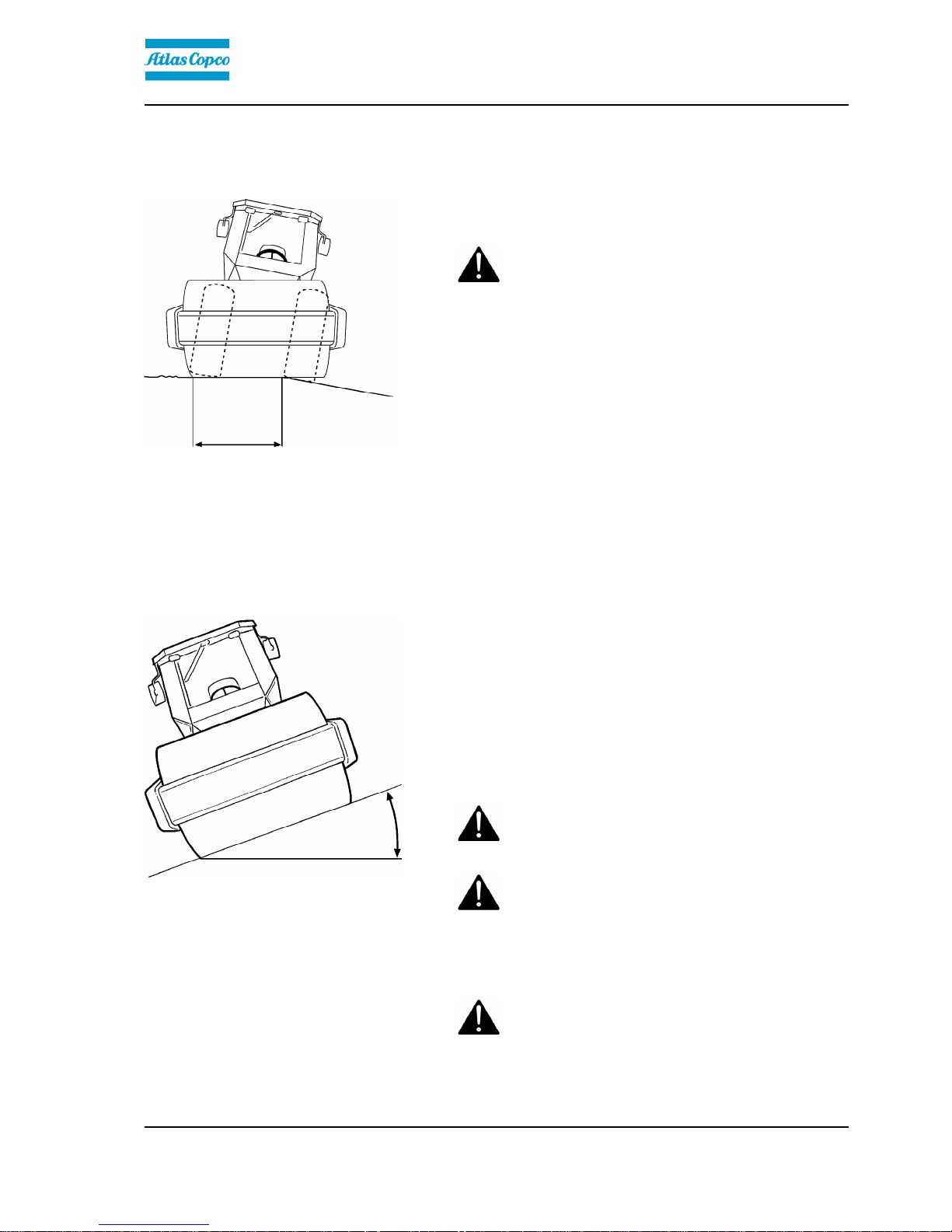
Driving near edges
Fig. Position of drum when driving near
an edge
Minimum
2/3
When driving near an edge, minimum 2/3 of the drum
width must be on solid ground.
Keep in mind that the machine's center of gravity
moves outwards when steering. For example, the
center of gravity moves to the right when you
steer to the left.
Keep in mind that the machine's center of gravity
moves outwards when steering. For example, the
center of gravity moves to the right when you
steer to the left.
Slopes
Fig. Operating on slopes
Max 20° or 36%
This angle has been measured on a hard, flat surface
with the machine stationary.
The steering angle was zero, the vibration was
switched OFF and all tanks were full.
Always take into consideration that loose ground,
steering the machine, vibration on, machine speed
across the ground and raising the center of gravity can
all cause the machine to topple at smaller slope
angles than those specified here.
To exit the cab in an emergency, release the
hammer on the rear right post and break the rear
window.
To exit the cab in an emergency, release the
hammer on the rear right post and break the rear
window.
It is recommended that ROPS (Roll Over Protective
Structure) or a ROPS-approved cab is always used
when driving on slopes or unsafe ground. Always
wear a seat belt.
It is recommended that ROPS (Roll Over Protective
Structure) or a ROPS-approved cab is always used
when driving on slopes or unsafe ground. Always
wear a seat belt.
Where possible, avoid driving across slopes.
Drive instead straight up and down sloping
ground.
Where possible, avoid driving across slopes.
Drive instead straight up and down sloping
ground.
5

Safety - when operating
ICA300-IN2EN1.pdf 2013-12-16
Air conditioning
The system described in this manual is type ACC
(Automatic Climate Control)
Fig. Cab
The system contains pressurized refrigerant. It
is forbidden to release refrigerants into the
atmosphere.
The system contains pressurized refrigerant. It
is forbidden to release refrigerants into the
atmosphere.
The cooling system is pressurized. Incorrect
handling can result in serious personal injury.
Do not disconnect or undo the hose couplings.
The cooling system is pressurized. Incorrect
handling can result in serious personal injury.
Do not disconnect or undo the hose couplings.
The system must be refilled with an approved
refrigerant by authorized personnel when
necessary.
The system must be refilled with an approved
refrigerant by authorized personnel when
necessary.
Fig. Air conditioning
6

Special instructions
ICA300-IN2EN1.pdf2013-12-16
Special instructions
Standard lubricants and other recommended
oils and fluids
Before leaving the factory, the systems and
components are filled with the oils and fluids specified
in the lubricant specification. These are suitable for
ambient temperatures in the range -15°C to +40°C
(5°F - 105°F).
Higher ambient temperatures, above +40°C
(104°F)
For operation of the machine at higher ambient
temperatures, however maximum +50°C (122°F), the
following recommendations apply:
The diesel engine can be run at this temperature using
normal oil. However, the following fluids must be used
for other components:
Hydraulic system - mineral oil Shell Tellus S2V100 or
similar.
Temperatures
The temperature limits apply to standard versions of
rollers.
Rollers equipped with additional equipment, such as
noise suppression, may need to be more carefully
monitored in the higher temperature ranges.
High pressure cleaning
Do not spray water directly onto electrical components
or the instrument panels.
Place a plastic bag over the fuel filler cap and secure
with a rubber band. This is to avoid high pressure
water entering the vent hole in the filler cap. This could
cause malfunctions, such as the blocking of filters.
Never aim the water jet directly at the fuel tank
cap. This is particularly important when using a
high-pressure cleaner.
Never aim the water jet directly at the fuel tank
cap. This is particularly important when using a
high-pressure cleaner.
Fire fighting
If the machine catches fire, use an ABC-class powder
fire extinguisher.
A BE-class carbon dioxide fire extinguisher can also
be used.
7

Special instructions
ICA300-IN2EN1.pdf 2013-12-16
Roll Over Protective Structure (ROPS), ROPS
approved cab
If the machine is fitted with a Roll Over
Protective Structure (ROPS, or ROPS approved
cab) never carry out any welding or drilling in
the structure or cab.
If the machine is fitted with a Roll Over
Protective Structure (ROPS, or ROPS approved
cab) never carry out any welding or drilling in
the structure or cab.
Never attempt to repair a damaged ROPS
structure or cab. These must be replaced with
new ROPS structure or cabs.
Never attempt to repair a damaged ROPS
structure or cab. These must be replaced with
new ROPS structure or cabs.
Battery handling
When removing batteries, always disconnect the
negative cable first.
When removing batteries, always disconnect the
negative cable first.
When fitting batteries, always connect the
positive cable first.
When fitting batteries, always connect the
positive cable first.
Dispose of old batteries in an environmentally
friendly way. Batteries contain toxic lead.
Dispose of old batteries in an environmentally
friendly way. Batteries contain toxic lead.
Do not use a quick-charger for charging the
battery. This may shorten battery life.
Do not use a quick-charger for charging the
battery. This may shorten battery life.
8
Special instructions
ICA300-IN2EN1.pdf2013-12-16
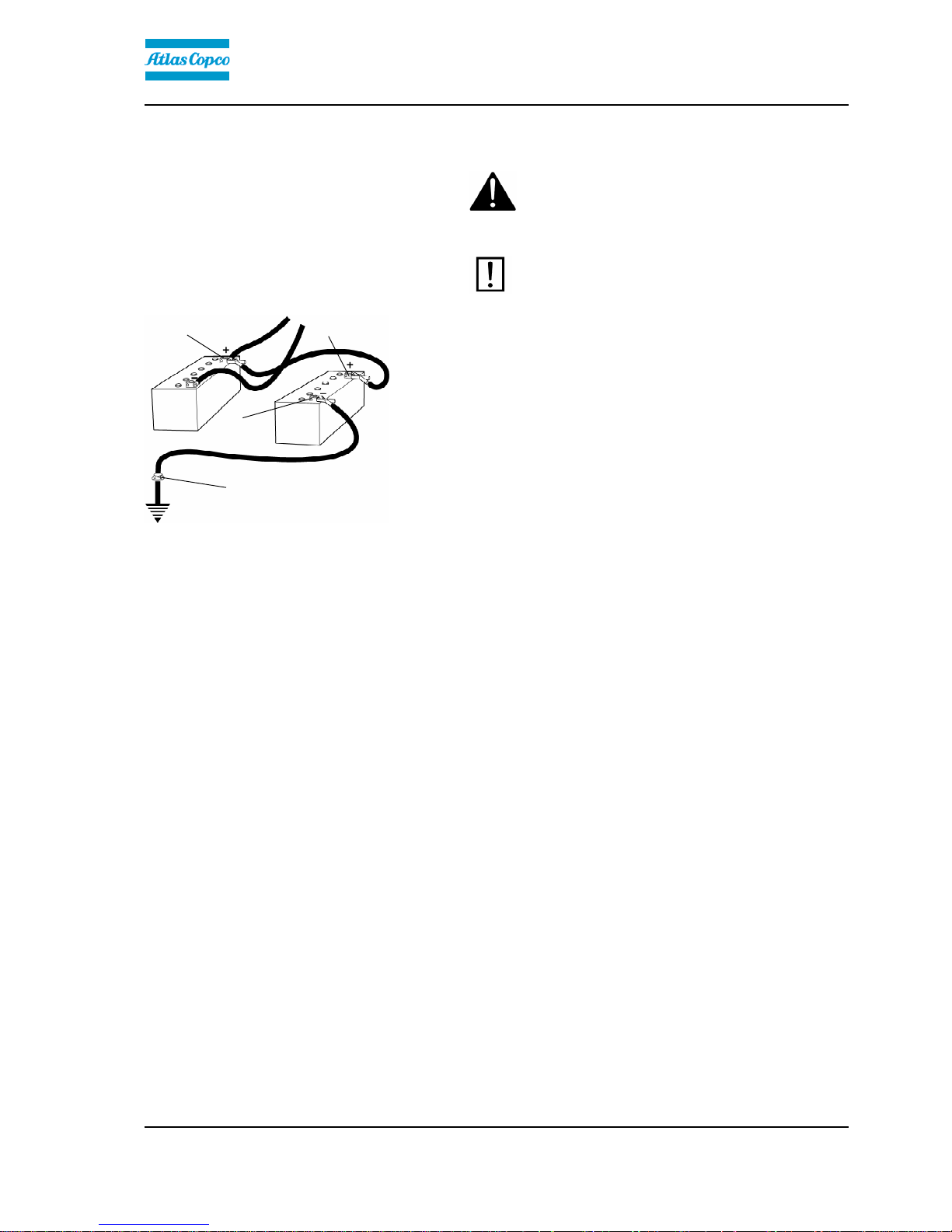
Jump starting
Do not connect the negative cable to the
negative terminal on the dead battery. A spark
can ignite the oxy-hydrogen gas formed
around the battery.
Do not connect the negative cable to the
negative terminal on the dead battery. A spark
can ignite the oxy-hydrogen gas formed
around the battery.
Check that the battery used for jump starting
has the same voltage as the dead battery.
Check that the battery used for jump starting
has the same voltage as the dead battery.
Fig. Jump starting
1
2
3
4
Turn the ignition and all power consuming equipment
off. Switch off the engine on the machine which is
providing jump start power.
First connect the jump start battery's positive terminal
(1) to the flat battery's positive terminal (2).Then
connect the jump start battery's negative terminal (3)
to, for example, a bolt (4) or the lifting eye on the
machine with the flat battery.
Start the engine on the power providing machine. Let it
run for a while. Now try to start the other machine.
Disconnect the cables in the reverse order.
9

Special instructions
ICA300-IN2EN1.pdf 2013-12-16
10

Technical specifications
ICA300-IN2EN1.pdf2013-12-16
Technical specifications
Vibrations - Operator station
(ISO 2631)
The vibration levels are measured in accordance with the operational cycle described in
EU directive 2000/14/EC on machines equipped for the EU market, with vibration switched
on, on soft polymer material and with the operator’s seat in the transport position.
The vibration levels are measured in accordance with the operational cycle described in
EU directive 2000/14/EC on machines equipped for the EU market, with vibration switched
on, on soft polymer material and with the operator’s seat in the transport position.
Measured whole-body vibrations are below the action value of 0.5 m/s² as specified in Directive
2002/44/EC. (Limit is 1.15 m/s²)
Measured whole-body vibrations are below the action value of 0.5 m/s² as specified in Directive
2002/44/EC. (Limit is 1.15 m/s²)
Measured hand/arm vibrations also were below the action level of 2.5 m/s² specified in the same
directive. (Limit is 5 m/s²)
Measured hand/arm vibrations also were below the action level of 2.5 m/s² specified in the same
directive. (Limit is 5 m/s²)
Noise level
The noise level is measured in accordance with the operational cycle described in EU
directive 2000/14/EC on machines equipped for the EU market, on soft polymer material
with vibration switched on and the operator's seat in the transport position.
The noise level is measured in accordance with the operational cycle described in EU
directive 2000/14/EC on machines equipped for the EU market, on soft polymer material
with vibration switched on and the operator's seat in the transport position.
Guaranteed sound power level, L
wA
107 dB (A)Guaranteed sound power level, L
wA
107 dB (A)
Sound pressure level at the operator's ear (platform), L
pA
90 ±3 dB (A)Sound pressure level at the operator's ear (platform), L
pA
90 ±3 dB (A)
Sound pressure level at the operator's ear (cab), L
pA
85 ±3 dB (A)Sound pressure level at the operator's ear (cab), L
pA
85 ±3 dB (A)
During operation the above values may differ because of the actual operational
conditions.
During operation the above values may differ because of the actual operational
conditions.
Electrical system
Machines are EMC tested in accordance with EN
13309:2000 'Construction machinery'
11
Technical specifications
ICA300-IN2EN1.pdf 2013-12-16
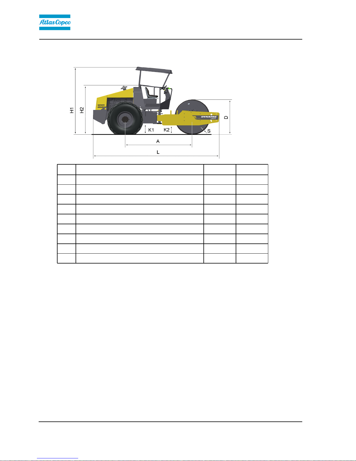
Dimensions, side view
Dimensions mm inDimensions mm in
A Wheelbase, drum and wheel 2879 113,3A Wheelbase, drum and wheel 2879 113,3
L Length, standard equipped roller 5550 218,5L Length, standard equipped roller 5550 218,5
H1 Height, with ROPS (STD, D) 2952 116,2H1 Height, with ROPS (STD, D) 2952 116,2
H1 Height, with cab (STD, D) 2952 116,2H1 Height, with cab (STD, D) 2952 116,2
H2 Height, without ROPS/cab (STD, D) 2190 86,2H2 Height, without ROPS/cab (STD, D) 2190 86,2
D Diameter, drum 1523 60D Diameter, drum 1523 60
S Thickness, drum sweep, nominal 25 0,98S Thickness, drum sweep, nominal 25 0,98
K1 Clearance, tractor frame 453 17,8K1 Clearance, tractor frame 453 17,8
K2 Clearance, drum frame (STD, D) 400 15,7K2 Clearance, drum frame (STD, D) 400 15,7
12
Technical specifications
ICA300-IN2EN1.pdf2013-12-16
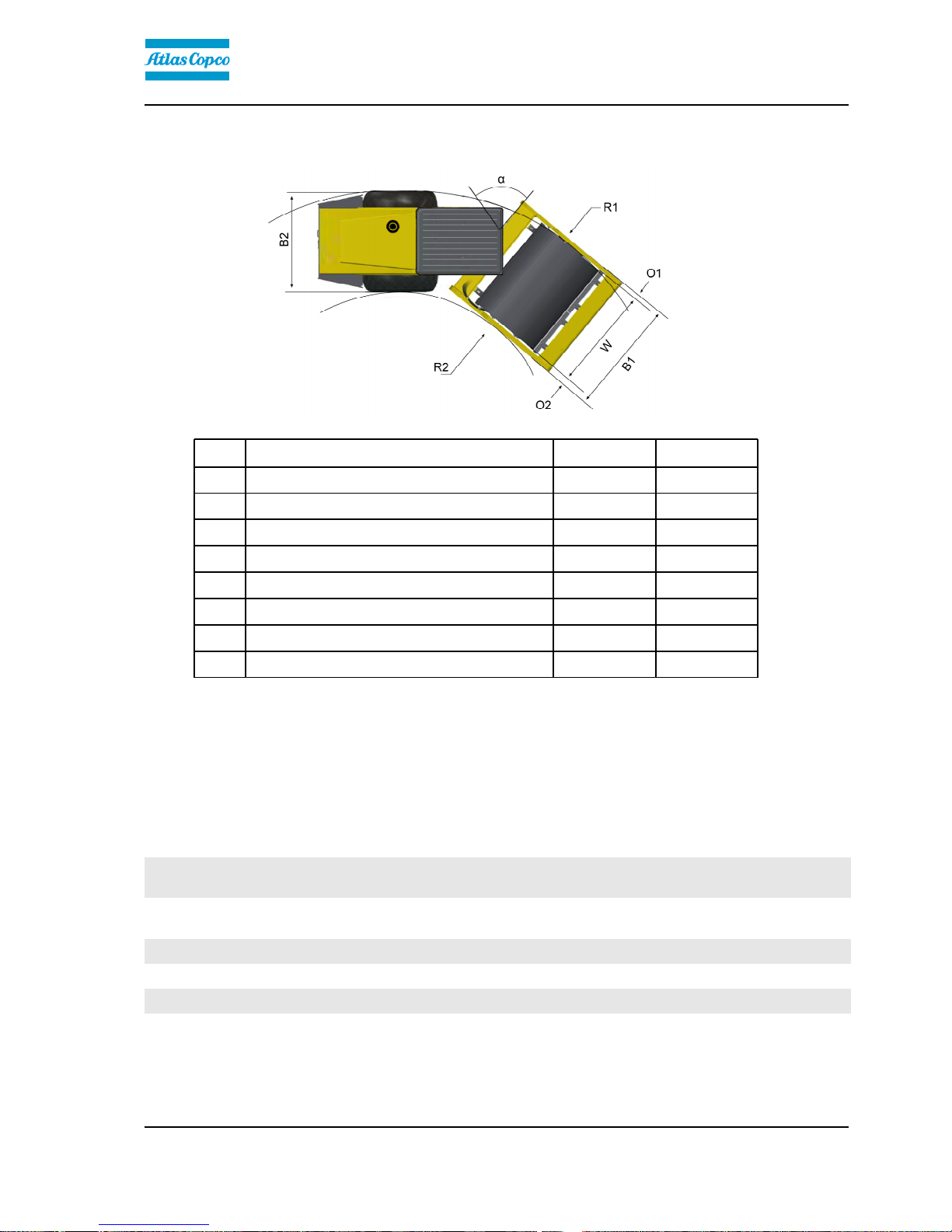
Dimensions, top view
Dimensions mm inDimensions mm in
B Width, standard equipped roller 2324 91,5B Width, standard equipped roller 2324 91,5
O 1 Overhang, left frame side 127 5,0O 1 Overhang, left frame side 127 5,0
O 2 Overhang, right frame side 127 5,0O 2 Overhang, right frame side 127 5,0
R 1 Turn radius, external 5400 212,6R 1 Turn radius, external 5400 212,6
R 2 Turn radius, internal 3100 122R 2 Turn radius, internal 3100 122
W 1 Width, tractor section 2130 83,9W 1 Width, tractor section 2130 83,9
W 2 Width, drum 2130 83.9W 2 Width, drum 2130 83.9
α Steering angle ± 38°α Steering angle ± 38°
Weights and volumes
WeightsWeights
Service weight with ROPS (EN500)
(STD)
12300 kg 27117 lbsService weight with ROPS (EN500)
(STD)
12300 kg 27117 lbs
Service weight with ROPS (EN500)
(D)
12550 kg 27670 lbsService weight with ROPS (EN500)
(D)
12550 kg 27670 lbs
Service weight without ROPS (STD) 11950 kg 26345 lbsService weight without ROPS (STD) 11950 kg 26345 lbs
Service weight without ROPS (D) 12200 kg 26900 lbsService weight without ROPS (D) 12200 kg 26900 lbs
Service weight, with cab (STD) 12500 kg 27558 lbsService weight, with cab (STD) 12500 kg 27558 lbs
Service weight with cab (D) 12750 kg 28110 lbsService weight with cab (D) 12750 kg 28110 lbs
13

Technical specifications
ICA300-IN2EN1.pdf 2013-12-16
Fluid volumesFluid volumes
Fuel tank 250 liters 66 galFuel tank 250 liters 66 gal
Working capacity
Compaction dataCompaction data
Static linear load (STD) 36,8 kg/cm 206,1 pliStatic linear load (STD) 36,8 kg/cm 206,1 pli
Static linear load (D) 38 kg/cm 212,8 pliStatic linear load (D) 38 kg/cm 212,8 pli
Static linear load, with ROPS (STD) 37,3 kg/cm 208,9 pliStatic linear load, with ROPS (STD) 37,3 kg/cm 208,9 pli
Static linear load with ROPS (D) 38,5 kg/cm 215,6 pliStatic linear load with ROPS (D) 38,5 kg/cm 215,6 pli
Static linear load, with cab(STD) 37,8 kg/cm 211,7 pliStatic linear load, with cab(STD) 37,8 kg/cm 211,7 pli
Static linear load with cab (D) 39 kg/cm 218,4 pliStatic linear load with cab (D) 39 kg/cm 218,4 pli
Amplitude, high (STD/D) 1.7 mm 0.066 inAmplitude, high (STD/D) 1.7 mm 0.066 in
Amplitude, low (STD/D) 0.8 mm 0.031 inAmplitude, low (STD/D) 0.8 mm 0.031 in
Vibration frequency, high amplitude 33 Hz 1980 vpmVibration frequency, high amplitude 33 Hz 1980 vpm
Vibration frequency, low amplitude 33 Hz 1980 vpmVibration frequency, low amplitude 33 Hz 1980 vpm
Centrifugal force, high amplitude (STD/D) 300 kN 67500 lbCentrifugal force, high amplitude (STD/D) 300 kN 67500 lb
Centrifugal force, low amplitude (STD/D) 146 kN 32850 lbCentrifugal force, low amplitude (STD/D) 146 kN 32850 lb
General
EngineEngine
Manufacturer/Model Cummins 4BTA 3.9C Water cooled turbo diesel with after
cooler
Manufacturer/Model Cummins 4BTA 3.9C Water cooled turbo diesel with after
cooler
Power (SAE J1995) 82 kW 110 hpPower (SAE J1995) 82 kW 110 hp
Engine speed 2200 rpmEngine speed 2200 rpm
Electrical systemElectrical system
Battery 12V 170AhBattery 12V 170Ah
Alternator 12V 95AAlternator 12V 95A
Fuses See the Electrical system section - fusesFuses See the Electrical system section - fuses
14

Technical specifications
ICA300-IN2EN1.pdf2013-12-16
Tire Tire dimensions Tire pressureTire Tire dimensions Tire pressure
Std-type 23.1 x 26.0 8 ply 110 kPa (1.1 kp/cm) (16 psi)Std-type 23.1 x 26.0 8 ply 110 kPa (1.1 kp/cm) (16 psi)
Tractor type 23.1 x 26.0 12 ply 110 kPa (1.1 kp/cm) (16 psi)Tractor type 23.1 x 26.0 12 ply 110 kPa (1.1 kp/cm) (16 psi)
The tires can be optionally filled with fluid, (extra
weight up to 500 kg/tire) (1102 lbs/tire). When
servicing, bear this extra weight in mind.
The tires can be optionally filled with fluid, (extra
weight up to 500 kg/tire) (1102 lbs/tire). When
servicing, bear this extra weight in mind.
Hydraulic system
Opening pressure MPaOpening pressure MPa
Drive system 38,0Drive system 38,0
Supply system 2.0Supply system 2.0
Vibration system * 42,5Vibration system * 42,5
Vibration system ** 30Vibration system ** 30
Control systems 17,5Control systems 17,5
Brake release 1,4Brake release 1,4
* Rexroth* Rexroth
**Sauer**Sauer
ROPS - bolts
Bolt dimensions : M24 (PN 4700904562)Bolt dimensions : M24 (PN 4700904562)
Strength class : 10.9Strength class : 10.9
Tightening torque : 800 Nm (Dacromet
treated)
Tightening torque : 800 Nm (Dacromet
treated)
ROPS-bolts which are to be torque tightened
must be dry.
ROPS-bolts which are to be torque tightened
must be dry.
15

Technical specifications
ICA300-IN2EN1.pdf 2013-12-16
Tightening torque
Tightening torque in Nm for oiled or dry bolts tightened
with a torque wrench.
M thread
8.8, Oiled 8.8, Dry 10.9, Oiled 10.9, Dry 12.9, Oiled 12.9, DryM -
thread
8.8, Oiled 8.8, Dry 10.9, Oiled 10.9, Dry 12.9, Oiled 12.9, Dry
M6 8,4 9,4 12 13,4 14,6 16,3M6 8,4 9,4 12 13,4 14,6 16,3
M8 21 23 28 32 34 38M8 21 23 28 32 34 38
M10 40 45 56 62 68 76M10 40 45 56 62 68 76
M12 70 78 98 110 117 131M12 70 78 98 110 117 131
M14 110 123 156 174 187 208M14 110 123 156 174 187 208
M16 169 190 240 270 290 320M16 169 190 240 270 290 320
M20 330 370 470 520 560 620M20 330 370 470 520 560 620
M22 446 497 626 699 752 839M22 446 497 626 699 752 839
M24 570 640 800 900 960 1080M24 570 640 800 900 960 1080
M30 1130 1260 1580 1770 1900 2100M30 1130 1260 1580 1770 1900 2100
STRENGTH CLASS:
Metric coarse screw thread, bright galvanized (fzb):
Metric coarse thread, zinc-treated
(Dacromet/GEOMET):
STRENGTH CLASS:
M - thread 10.9, Oiled 10.9, Dry 12.9, Oiled 12.9, Dry M - thread 10.9, Oiled 10.9, Dry 12.9, Oiled 12.9, Dry
M6 12,0 15,0 14,6 18,3M6 12,0 15,0 14,6 18,3
M8 28 36 34 43M8 28 36 34 43
M10 56 70 68 86M10 56 70 68 86
M12 98 124 117 147M12 98 124 117 147
M14 156 196 187 234M14 156 196 187 234
M16 240 304 290 360M16 240 304 290 360
M20 470 585 560 698M20 470 585 560 698
M22 626 786 752 944M22 626 786 752 944
M24 800 1010 960 1215M24 800 1010 960 1215
M30 1580 1990 1900 2360M30 1580 1990 1900 2360
16

Machine description
ICA300-IN2EN1.pdf2013-12-16
Machine description
Identification
1
1
Fig. Front frame
1. PIN
Product identification number on the frame
The machine PIN (product identification number) (1) is
punched on the right edge of the front frame or the
upper edge of the right frameside.
1
Fig. Operator platform
1. Machine plate
Machine plate
The machine type plate (1) is attached to the front left
side of the frame, beside the steering joint.
The plate specifies the manufacturers name and
address, the type of machine, the PIN product
identification number (serial number), operating
weight, engine power and year of manufacture. (If the
machine is supplied to outside the EU, there are no
CE markings and in some cases no year of
manufacture.)
Fig. Machine plate
Please state the machine's PIN when ordering
spares.
17
Machine description
ICA300-IN2EN1.pdf 2013-12-16
Explanation of 17PIN serial number
100 00123 V 0 A 123456100 00123 V 0 A 123456
A B C D E FA B C D E F
A= Manufacturer
B= Family/Model
C= Check letter
D= No coding
E= Production unit
F= Serial number
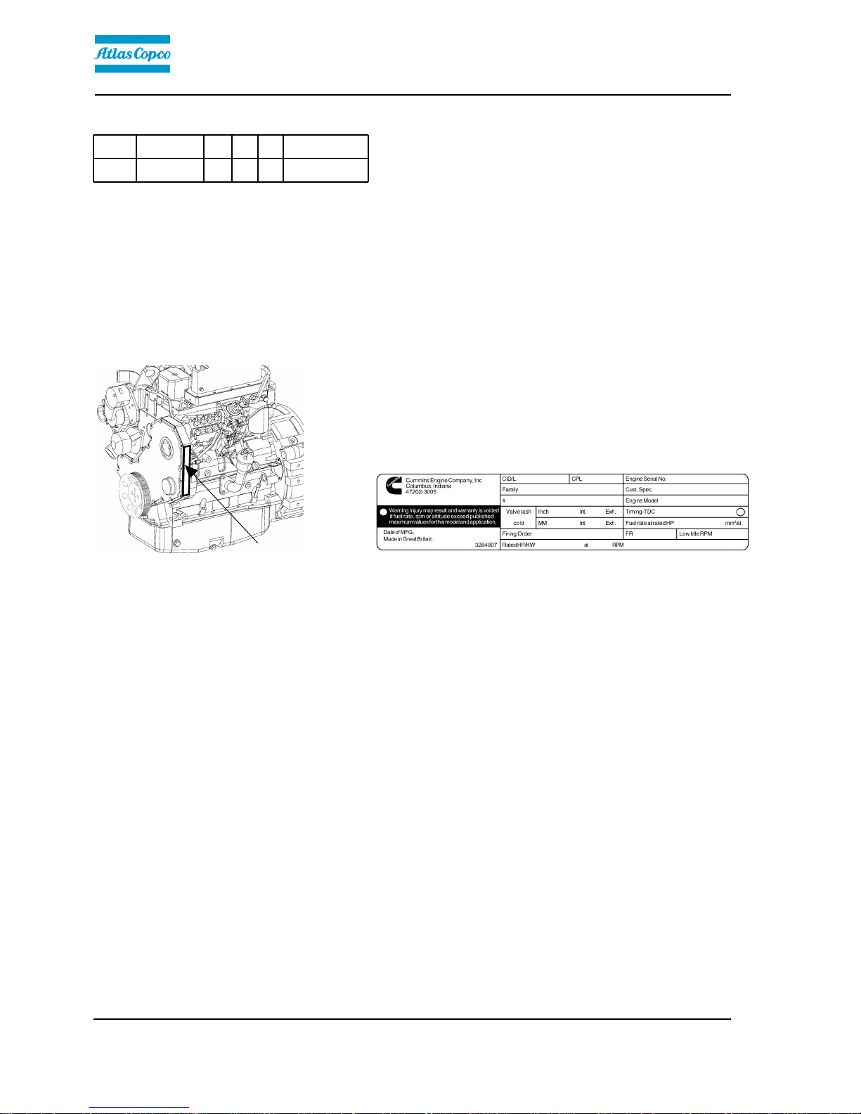
Engine plates
1
Fig. Engine
1. Type plate
The engine plate (1) is affixed to the right side of the
engine.
The plate specifies the type of engine, its serial
number and the engine specification.
Fig. Type plate
Please specify the engine serial number when
ordering spares. Refer also to the engine manual.
18
Machine description
ICA300-IN2EN1.pdf2013-12-16
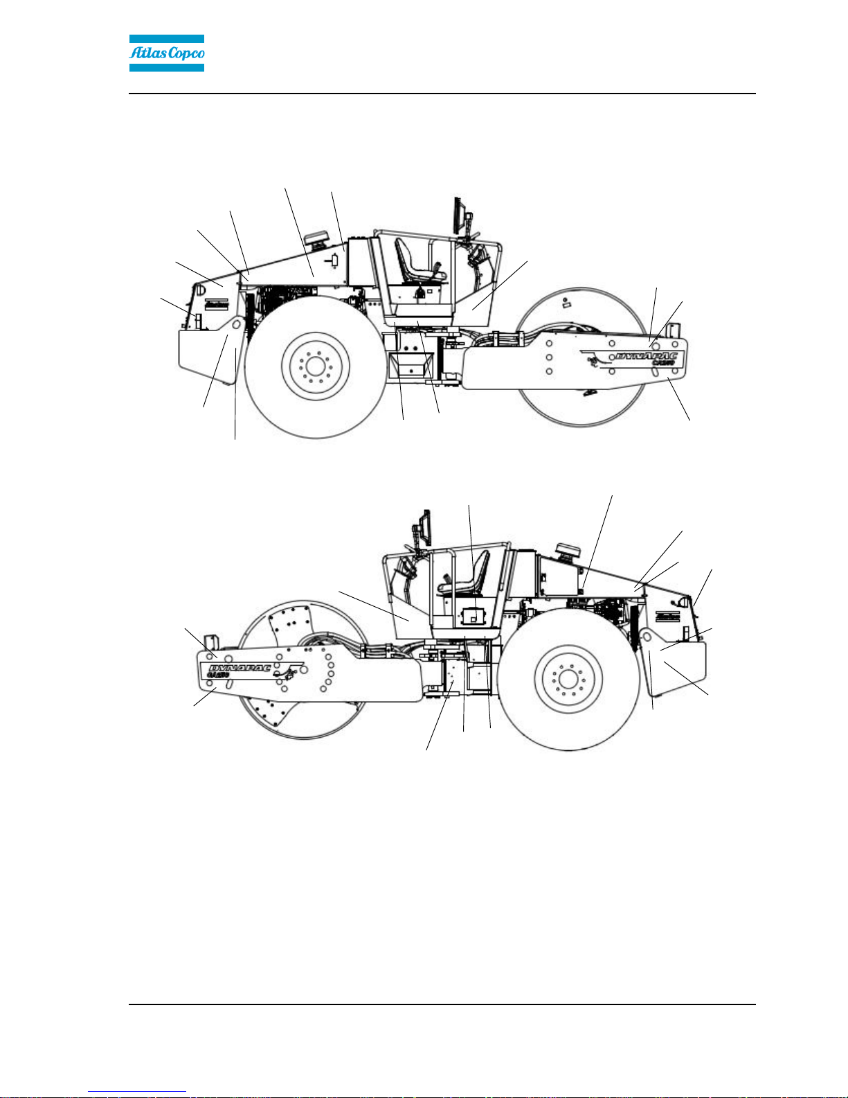
Decals
Location - decals
3
10
13
2
16
8
1
11
11
14
123
6
1
15
7
9
15
11
10
11
2
445
6
14
5
1. Warning, Crush
zone
4700903422 7. Product sign 13. Handbook
compartment
47009034251. Warning, Crush
zone
4700903422 7. Product sign 13. Handbook
compartment
4700903425
2. Warning, Rotating
engine components
4700903423 8. Diesel fuel 4700991658 14. Tire pressure 4700991990
4700390900
2. Warning, Rotating
engine components
4700903423 8. Diesel fuel 4700991658 14. Tire pressure 4700991990
4700390900
3. Warning, Hot
surfaces
4700903424 9. Hydraulic fluid 4700272372 15. Hoisting plate 47009048703. Warning, Hot
surfaces
4700903424 9. Hydraulic fluid 4700272372 15. Hoisting plate 4700904870
4. Reflector, yellow 4700377744 10. Lifting point 4700588176 16. Hydraulic fluid 47002723734. Reflector, yellow 4700377744 10. Lifting point 4700588176 16. Hydraulic fluid 4700272373
5. Warning,
Instruction manual
4700903459 11. Fixing point 47003827515. Warning,
Instruction manual
4700903459 11. Fixing point 4700382751
6. Warning, locking 470098229 12. Master switch 47009048356. Warning, locking 470098229 12. Master switch 4700904835
19
Machine description
ICA300-IN2EN1.pdf 2013-12-16
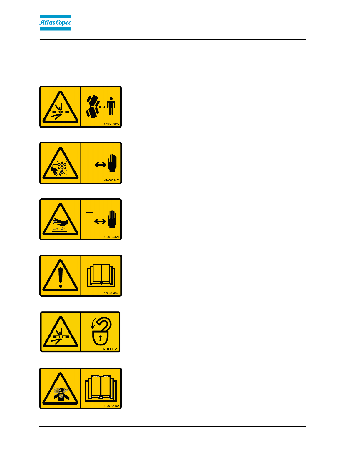
Safety decals
Always make sure that all safety decals are completely
legible, and remove dirt or order new decals if they
have become illegible. Use the part number specified
on each decal.
4700903422
Warning - Crush zone, articulation/drum.
Maintain a safe distance from the crush zone.
(Two crush zones on machines fitted with pivotal steering)
4700903423
Warning - Rotating engine components.
Keep your hands at a safe distance from the
danger zone.
4700903424
Warning - Hot surfaces in the engine compartment.
Keep your hands at a safe distance from the
danger zone.
4700903459
Warning - Instruction manual
The operator must read the safety, operation and
maintenance instructions before operating the
machine.
4700908229
Warning - Risk of crushing
The articulation must be locked when lifting.
Read the instruction manual.
4700904165
Warning - Toxic gas (option, ACC)
Read the instruction manual.
20

Machine description
ICA300-IN2EN1.pdf2013-12-16
4700903590
-Emergency exit
4700903985
Warning - Ballasted tire.
Read the instruction manual.
21
Machine description
ICA300-IN2EN1.pdf 2013-12-16
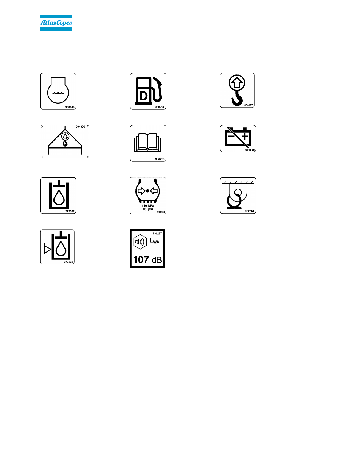
Info decals
Coolant Diesel fuel Lifting pointCoolant Diesel fuel Lifting point
Hoisting plate Handbook compartment Master switchHoisting plate Handbook compartment Master switch
Hydraulic fluid Tire pressure Securing pointHydraulic fluid Tire pressure Securing point
Hydraulic fluid level Noise power levelHydraulic fluid level Noise power level
22
 Loading...