

Atlas Copco BBS1100, BBSE1100 Repair Instructions
Repair Instructions No.521.09/00
BBS(E)1100
BBS(E)1100
Atlas Copco
Electric Power Tools Ltd.
4939 5240 01
(10/00)
1
PAGE
Repair Instructions No.521.09/00
BBS(E)1100
Special Tools
Require
■
Forcing discs 4931 5990 18
Important!
■
Before beginning the maintenance work, perform an initial check with a high voltage test according
to VDE (see chapter Electrical and Mechanical Test Instructions).
■
Before all repair work, pull the power plug from the socket!
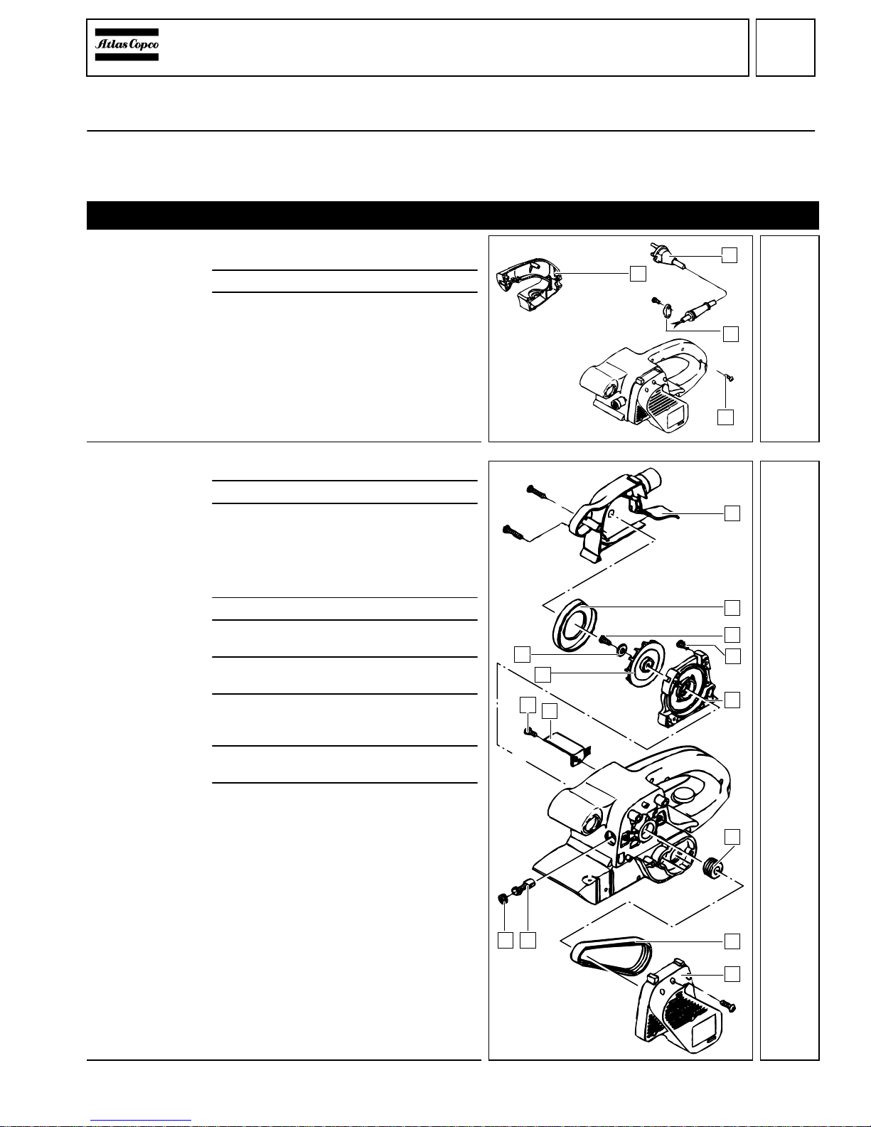
Disassembly
Detaching the
handle cover
1
Loosen all five screws (4) and remove the
handle cover (1).
2
Unscrew the strain relief (3).
3
Remove the connection cable (2) from the
handle shell.
Detaching the
toothed belt,
Removing the
carbon brushes
1
Unscrew the blower cover (1).
2
Remove the air deflector ring (2).
3
Unscrew the centric screw (3) of the
fan (A) and remove the sealing washer (9).
☞
At the same time, steady the fan (A) for
support.
4
Remove the fan (A).
5
Loosen four screws (4) and remove the
bearing end plate (5).
6
Remove the belt guard (8) and lever off/
twist off the toothed belt (7).
7
Unscrew the two brush holder caps (B)
and remove the carbon brushes (C) on
both sides.
8
Loosen the screw (D)and remove the triac (E).
9
Unscrew the pulley (6) with aid of a pipe
wrench (put a piece of cloth in between).
At the same time, carefully steady the armature, or remove the armature from the
machine.
☞
The pulley has a left-handed thread!
4
1
2
3
1
1
8
3
5
A
2
9
7
6
CB
4
D
E
2
2
PAGE
Repair Instructions No.521.09/00
BBS(E)1100
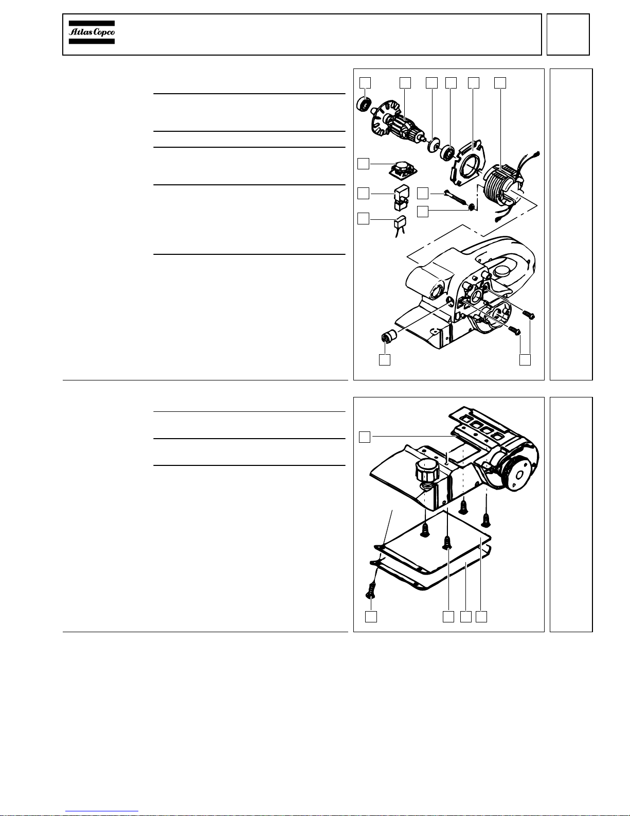
Removing the
field and the
armature
1
Pull out the armature (2) and remove the
air deflector ring (5).
2
Press off two ball bearings (1) and (4) from
the armature (2) with aid of the forcing
discs (service tool).
3
Remove the seal ring (3).
4
Loosen both field screws (A) and remove
the spring washers (B). Branch off the
field (6) and remove it.
5
The switch (8) and the capacitor (9) can
now be removed from the housing shell.
Only applicable for BBSE 1100:
Remove the electronic element with
torque setting wheel (7) from the housing
shell.
6
Loosen both screws (D) and remove the
carbon brush holders (C) on both sides.
Detaching the
spring steel
sheet
1
Loosen two screws (1).
2
Remove the spring steel sheet (3) and the
support for the sand belt (4).
3
Unscrew the four screws (2) through the
openings in the absolute unit.
4
Remove the absolute unit (5) from the motor housing.
2 3 4 5 6
7
8
9
C
A
B
1
D
3
21 3 4
5
4
 Loading...