

Atlas Copco BBD 12, BBD 15 Safety And Operating Instructions Manual
BBD
Safety and operating instructions
Rock drills
Prescriptions de sécurité et instructions pour
l’opérateur
Perforateur
Sicherheits- und Betriebsanleitung
Bohrhämmer
Instrucciones de seguridad y de funcionamiento
Perforadoras
Instruções de segurança e operação
Perfuradores de rocha
Istruzioni per la sicurezza e per l'uso
12, 15
Perforatrici
Veiligheidsvoorschriften en bedieningshandleiding
Steenboren
Οδηγίες ασφάλειας και χειρισμού
Γεωτρύπανα
Turvallisuusohjeet ja käyttöohje
Kallioporat
Sikkerhedsinstruktioner og betjeningsvejledning
Bjergborehamre
Sikkerhetsinstrukser og bruksanvisning
Bergboremaskiner
Säkerhetsinstruktion och instruktionsbok
Bergborrmaskiner
© 2010 Atlas Copco Construction Tools AB | No. 9800 0937 90 | 2010-01-01
Original instructions


ContentsBBD 12, 15
Contents
ENGLISH. . . . . . . . . . . . . . . . . . . . . . . . . . . . . . . . . . . . . . . . . . . . . . . . . . . . . . . . . . . . . . . . . . . . . . . . . . . 4
FRANÇAIS. . . . . . . . . . . . . . . . . . . . . . . . . . . . . . . . . . . . . . . . . . . . . . . . . . . . . . . . . . . . . . . . . . . . . . . . 26
DEUTSCH. . . . . . . . . . . . . . . . . . . . . . . . . . . . . . . . . . . . . . . . . . . . . . . . . . . . . . . . . . . . . . . . . . . . . . . . . 50
ESPAÑOL. . . . . . . . . . . . . . . . . . . . . . . . . . . . . . . . . . . . . . . . . . . . . . . . . . . . . . . . . . . . . . . . . . . . . . . . . 74
PORTUGUÊS. . . . . . . . . . . . . . . . . . . . . . . . . . . . . . . . . . . . . . . . . . . . . . . . . . . . . . . . . . . . . . . . . . . . . . 98
ITALIANO. . . . . . . . . . . . . . . . . . . . . . . . . . . . . . . . . . . . . . . . . . . . . . . . . . . . . . . . . . . . . . . . . . . . . . . . 122
NEDERLANDS. . . . . . . . . . . . . . . . . . . . . . . . . . . . . . . . . . . . . . . . . . . . . . . . . . . . . . . . . . . . . . . . . . . 144
ΕΛΛΗΝΙΚΑ. . . . . . . . . . . . . . . . . . . . . . . . . . . . . . . . . . . . . . . . . . . . . . . . . . . . . . . . . . . . . . . . . . . . . . . 168
SUOMI. . . . . . . . . . . . . . . . . . . . . . . . . . . . . . . . . . . . . . . . . . . . . . . . . . . . . . . . . . . . . . . . . . . . . . . . . . . 192
DANSK. . . . . . . . . . . . . . . . . . . . . . . . . . . . . . . . . . . . . . . . . . . . . . . . . . . . . . . . . . . . . . . . . . . . . . . . . . 214
NORSK. . . . . . . . . . . . . . . . . . . . . . . . . . . . . . . . . . . . . . . . . . . . . . . . . . . . . . . . . . . . . . . . . . . . . . . . . . 236
SVENSKA. . . . . . . . . . . . . . . . . . . . . . . . . . . . . . . . . . . . . . . . . . . . . . . . . . . . . . . . . . . . . . . . . . . . . . . . 258
Original instructions
3© 2010 Atlas Copco Construction Tools AB | No. 9800 0937 90 | 2010-01-01

BBD 12, 15Contents
ENGLISH
Contents
Introduction. . . . . . . . . . . . . . . . . . . . . . . . . . . . . . . . . . . . . . . . . . . . . . . . . . . . . . . . . . . . . . . . . . . . . . . . 7
About the Safety and operating instructions. . . . . . . . . . . . . . . . . . . . . . . . . . . . . . . . . . . . . . . . . . 7
Safety instructions. . . . . . . . . . . . . . . . . . . . . . . . . . . . . . . . . . . . . . . . . . . . . . . . . . . . . . . . . . . . . . . . . 8
Safety signal words. . . . . . . . . . . . . . . . . . . . . . . . . . . . . . . . . . . . . . . . . . . . . . . . . . . . . . . . . . . . . . 8
Personal precautions and qualifications. . . . . . . . . . . . . . . . . . . . . . . . . . . . . . . . . . . . . . . . . . . 8
Personal protective equipment. . . . . . . . . . . . . . . . . . . . . . . . . . . . . . . . . . . . . . . . . . . . . . . . . . . 8
Drugs, alcohol or medication. . . . . . . . . . . . . . . . . . . . . . . . . . . . . . . . . . . . . . . . . . . . . . . . . . . . 8
Installation, precautions. . . . . . . . . . . . . . . . . . . . . . . . . . . . . . . . . . . . . . . . . . . . . . . . . . . . . . . . . . 8
Operation, precautions. . . . . . . . . . . . . . . . . . . . . . . . . . . . . . . . . . . . . . . . . . . . . . . . . . . . . . . . . . . 9
Maintenance, precautions. . . . . . . . . . . . . . . . . . . . . . . . . . . . . . . . . . . . . . . . . . . . . . . . . . . . . . . 12
Storage, precautions. . . . . . . . . . . . . . . . . . . . . . . . . . . . . . . . . . . . . . . . . . . . . . . . . . . . . . . . . . . . 12
Overview. . . . . . . . . . . . . . . . . . . . . . . . . . . . . . . . . . . . . . . . . . . . . . . . . . . . . . . . . . . . . . . . . . . . . . . . . 13
Design and function. . . . . . . . . . . . . . . . . . . . . . . . . . . . . . . . . . . . . . . . . . . . . . . . . . . . . . . . . . . . 13
Working principle of a rock drill. . . . . . . . . . . . . . . . . . . . . . . . . . . . . . . . . . . . . . . . . . . . . . . . . 13
Control valve mechanism. . . . . . . . . . . . . . . . . . . . . . . . . . . . . . . . . . . . . . . . . . . . . . . . . . . . . . 13
Rotation mechanism. . . . . . . . . . . . . . . . . . . . . . . . . . . . . . . . . . . . . . . . . . . . . . . . . . . . . . . . . . 13
Flushing. . . . . . . . . . . . . . . . . . . . . . . . . . . . . . . . . . . . . . . . . . . . . . . . . . . . . . . . . . . . . . . . . . . . . 13
Main parts. . . . . . . . . . . . . . . . . . . . . . . . . . . . . . . . . . . . . . . . . . . . . . . . . . . . . . . . . . . . . . . . . . . . . 13
Labels. . . . . . . . . . . . . . . . . . . . . . . . . . . . . . . . . . . . . . . . . . . . . . . . . . . . . . . . . . . . . . . . . . . . . . . . . 14
Data plate. . . . . . . . . . . . . . . . . . . . . . . . . . . . . . . . . . . . . . . . . . . . . . . . . . . . . . . . . . . . . . . . . . . . 14
Safety label. . . . . . . . . . . . . . . . . . . . . . . . . . . . . . . . . . . . . . . . . . . . . . . . . . . . . . . . . . . . . . . . . . 14
Installation. . . . . . . . . . . . . . . . . . . . . . . . . . . . . . . . . . . . . . . . . . . . . . . . . . . . . . . . . . . . . . . . . . . . . . . . 14
Unpacking the rock drill. . . . . . . . . . . . . . . . . . . . . . . . . . . . . . . . . . . . . . . . . . . . . . . . . . . . . . . . . 14
Plastic guards. . . . . . . . . . . . . . . . . . . . . . . . . . . . . . . . . . . . . . . . . . . . . . . . . . . . . . . . . . . . . . . . 14
Assembly. . . . . . . . . . . . . . . . . . . . . . . . . . . . . . . . . . . . . . . . . . . . . . . . . . . . . . . . . . . . . . . . . . . . 15
Lubricate. . . . . . . . . . . . . . . . . . . . . . . . . . . . . . . . . . . . . . . . . . . . . . . . . . . . . . . . . . . . . . . . . . . . 15
Hoses and connections. . . . . . . . . . . . . . . . . . . . . . . . . . . . . . . . . . . . . . . . . . . . . . . . . . . . . . . . . 15
Methods to prevent freezing. . . . . . . . . . . . . . . . . . . . . . . . . . . . . . . . . . . . . . . . . . . . . . . . . . . . . 15
Connecting a water separator. . . . . . . . . . . . . . . . . . . . . . . . . . . . . . . . . . . . . . . . . . . . . . . . . . . 15
Lubrication. . . . . . . . . . . . . . . . . . . . . . . . . . . . . . . . . . . . . . . . . . . . . . . . . . . . . . . . . . . . . . . . . . . . . 15
Pressure adjustment. . . . . . . . . . . . . . . . . . . . . . . . . . . . . . . . . . . . . . . . . . . . . . . . . . . . . . . . . . . . 16
Air pressure. . . . . . . . . . . . . . . . . . . . . . . . . . . . . . . . . . . . . . . . . . . . . . . . . . . . . . . . . . . . . . . . . . 16
Calibrate the correct air pressure. . . . . . . . . . . . . . . . . . . . . . . . . . . . . . . . . . . . . . . . . . . . . . . . 16
Drill steel. . . . . . . . . . . . . . . . . . . . . . . . . . . . . . . . . . . . . . . . . . . . . . . . . . . . . . . . . . . . . . . . . . . . . . 16
Before fitting the drill steel. . . . . . . . . . . . . . . . . . . . . . . . . . . . . . . . . . . . . . . . . . . . . . . . . . . . . . 16
Fitting the drill steel. . . . . . . . . . . . . . . . . . . . . . . . . . . . . . . . . . . . . . . . . . . . . . . . . . . . . . . . . . . 16
Removing the drill steel. . . . . . . . . . . . . . . . . . . . . . . . . . . . . . . . . . . . . . . . . . . . . . . . . . . . . . . . 17
Operation. . . . . . . . . . . . . . . . . . . . . . . . . . . . . . . . . . . . . . . . . . . . . . . . . . . . . . . . . . . . . . . . . . . . . . . . . 17
Preparations before starting. . . . . . . . . . . . . . . . . . . . . . . . . . . . . . . . . . . . . . . . . . . . . . . . . . . . . 18
Check the drilling equipment. . . . . . . . . . . . . . . . . . . . . . . . . . . . . . . . . . . . . . . . . . . . . . . . . . . 18
Blow out the air hose. . . . . . . . . . . . . . . . . . . . . . . . . . . . . . . . . . . . . . . . . . . . . . . . . . . . . . . . . . 18
Fill the lubricator with oil. . . . . . . . . . . . . . . . . . . . . . . . . . . . . . . . . . . . . . . . . . . . . . . . . . . . . . . 18
Controls. . . . . . . . . . . . . . . . . . . . . . . . . . . . . . . . . . . . . . . . . . . . . . . . . . . . . . . . . . . . . . . . . . . . . . . 18
Throttle lever. . . . . . . . . . . . . . . . . . . . . . . . . . . . . . . . . . . . . . . . . . . . . . . . . . . . . . . . . . . . . . . . . 18
Start and stop. . . . . . . . . . . . . . . . . . . . . . . . . . . . . . . . . . . . . . . . . . . . . . . . . . . . . . . . . . . . . . . . . . 19
Starting the rock drill. . . . . . . . . . . . . . . . . . . . . . . . . . . . . . . . . . . . . . . . . . . . . . . . . . . . . . . . . . 19
Stopping the rock drill. . . . . . . . . . . . . . . . . . . . . . . . . . . . . . . . . . . . . . . . . . . . . . . . . . . . . . . . . 19
Operating. . . . . . . . . . . . . . . . . . . . . . . . . . . . . . . . . . . . . . . . . . . . . . . . . . . . . . . . . . . . . . . . . . . . . . 19
Drilling. . . . . . . . . . . . . . . . . . . . . . . . . . . . . . . . . . . . . . . . . . . . . . . . . . . . . . . . . . . . . . . . . . . . . . . 19
When taking a break. . . . . . . . . . . . . . . . . . . . . . . . . . . . . . . . . . . . . . . . . . . . . . . . . . . . . . . . . . . . 19
4
© 2010 Atlas Copco Construction Tools AB | No. 9800 0937 90 | 2010-01-01
Original instructions

ContentsBBD 12, 15
Maintenance. . . . . . . . . . . . . . . . . . . . . . . . . . . . . . . . . . . . . . . . . . . . . . . . . . . . . . . . . . . . . . . . . . . . . . 19
Differences between original parts and pattern parts. . . . . . . . . . . . . . . . . . . . . . . . . . . . . . 19
Every day. . . . . . . . . . . . . . . . . . . . . . . . . . . . . . . . . . . . . . . . . . . . . . . . . . . . . . . . . . . . . . . . . . . . . . 20
Checking for wear. . . . . . . . . . . . . . . . . . . . . . . . . . . . . . . . . . . . . . . . . . . . . . . . . . . . . . . . . . . . . . 20
Periodic maintenance. . . . . . . . . . . . . . . . . . . . . . . . . . . . . . . . . . . . . . . . . . . . . . . . . . . . . . . . . . . 20
Tightening torque. . . . . . . . . . . . . . . . . . . . . . . . . . . . . . . . . . . . . . . . . . . . . . . . . . . . . . . . . . . . . . . 21
Damage patterns. . . . . . . . . . . . . . . . . . . . . . . . . . . . . . . . . . . . . . . . . . . . . . . . . . . . . . . . . . . . . . . 21
Storage. . . . . . . . . . . . . . . . . . . . . . . . . . . . . . . . . . . . . . . . . . . . . . . . . . . . . . . . . . . . . . . . . . . . . . . . . . . 21
Disposal. . . . . . . . . . . . . . . . . . . . . . . . . . . . . . . . . . . . . . . . . . . . . . . . . . . . . . . . . . . . . . . . . . . . . . . . . . 21
Technical data. . . . . . . . . . . . . . . . . . . . . . . . . . . . . . . . . . . . . . . . . . . . . . . . . . . . . . . . . . . . . . . . . . . . . 22
Machine data. . . . . . . . . . . . . . . . . . . . . . . . . . . . . . . . . . . . . . . . . . . . . . . . . . . . . . . . . . . . . . . . . . . 22
Noise and vibration declaration statement. . . . . . . . . . . . . . . . . . . . . . . . . . . . . . . . . . . . . . . . 22
Noise and vibration data. . . . . . . . . . . . . . . . . . . . . . . . . . . . . . . . . . . . . . . . . . . . . . . . . . . . . . . . 23
Accessories. . . . . . . . . . . . . . . . . . . . . . . . . . . . . . . . . . . . . . . . . . . . . . . . . . . . . . . . . . . . . . . . . . . . 23
EC Declaration of Conformity. . . . . . . . . . . . . . . . . . . . . . . . . . . . . . . . . . . . . . . . . . . . . . . . . . . . . . 24
EC Declaration of Conformity (EC Directive 2006/42/EC). . . . . . . . . . . . . . . . . . . . . . . . . . . 24
Original instructions
5© 2010 Atlas Copco Construction Tools AB | No. 9800 0937 90 | 2010-01-01


Safety and operating instructionsBBD 12, 15
Introduction
Thank you for choosing a product from Atlas Copco. Since 1873, we have been
committed to finding new and better ways of fulfilling our customers' needs.
Through the years, we have developed innovative and ergonomic product
designs that have helped customers improve and rationalize their daily work.
Atlas Copco has a strong global sales and service network, consisting of
customer centers and distributors worldwide. Our experts are highly trained
professionals with extensive product knowledge and application experience.
In all corners of the world, we can offer product support and expertise to ensure
that our customers can work at maximum efficiency at all times.
For more information please visit: www.atlascopco.com
Atlas Copco Construction Tools AB
105 23 Stockholm
Sweden
About the Safety and operating
instructions
The aim of the instructions is to provide you with knowledge of how to use the
rock drill in an efficient, safe way. The instructions also give you advice and
tell you how to perform regular maintenance on the rock drill.
Before using the rock drill for the first time you must read these instructions
carefully and understand all of them.
Original instructions
7© 2010 Atlas Copco Construction Tools AB | No. 9800 0937 90 | 2010-01-01

BBD 12, 15Safety and operating instructions
Safety instructions
To reduce the risk of serious injury or death to
yourself or others, read and understand the Safety
and operating instruction before installing, operating,
repairing, maintaining, or changing accessories on
the machine.
Post this Safety and operating instruction at work
locations, provide copies to employees, and make
sure that everyone reads the Safety and operating
instruction before operating or servicing the machine.
In addition, the operator or the operator's employer
must assess the specific risks that may be present
as a result of each use of the machine.
Safety signal words
The safety signal words Danger, Warning and
Caution have the following meanings:
DANGER
WARNING
CAUTION
Personal precautions and
qualifications
Only qualified and trained persons may operate or
maintain the machine. They must be physically able
to handle the bulk, weight, and power of the tool.
Always use your common sense and good
judgement.
Personal protective equipment
Always use approved protective equipment.
Operators and all other persons in the working area
must wear protective equipment, including at a
minimum:
● Protective helmet
Indicates a hazardous situation
which, if not avoided, will result
in death or serious injury.
Indicates a hazardous situation
which, if not avoided, could
result in death or serious injury.
Indicates a hazardous situation
which, if not avoided, could
result in minor or moderate
injury.
Drugs, alcohol or medication
WARNING Drugs, alcohol or medication
Drugs, alcohol or medication may impair your
judgment and powers of concentration. Poor
reactions and incorrect assessments can lead to
severe accidents or death.
► Never use the machine when you are tired or
under the influence of drugs, alcohol or
medication.
► No person who is under the influence of drugs,
alcohol or medication may operate the machine.
Installation, precautions
DANGER Whipping air hose
A compressed air hose that comes loose can lash
around and cause personal injury or death. To reduce
this risk:
► Check that the compressed air hose and the
connections are not damaged, replace if
necessary.
► Check that all compressed air connections are
properly attached.
► Never carry a pneumatic machine by the air hose.
► Never attempt to disconnect a compressed air
hose that is pressurized. First switch off the
compressed air at the compressor and then bleed
the machine by activating the start and stop
device.
► Never point a compressed air hose at yourself or
anyone else. To avoid the risk of getting injured,
never use compressed air to blow for example
dust, dirt etc. from your clothes.
► Do not use quick disconnect couplings at tool inlet.
Use hardened steel (or material with comparable
shock resistance) threaded hose fittings.
► Whenever universal twist couplings (claw
couplings) are used, we recommend that lock pins
are installed and whipcheck safety cables are used
to safeguard against possible hose to tool and
hose to hose connection failure.
● Hearing protection
● Impact resistant eye protection with side protection
● Respiratory protection when appropriate
● Protective gloves
● Proper protective boots
● Appropriate work overall or similar clothing (not
loose-fitting) that covers your arms and legs.
8
© 2010 Atlas Copco Construction Tools AB | No. 9800 0937 90 | 2010-01-01
Original instructions

Safety and operating instructionsBBD 12, 15
WARNING Ejected insertion tool
If the tool retainer on the machine is not in a locked
position, the inserted tool can be ejected with force,
which can cause personal injury.
► Never start the machine while changing the
insertion tool.
► Before changing the insertion tool or accessories,
stop the machine, switch off the power supply and
bleed the machine by activating the start and stop
device.
► Never point the inserted tool at yourself or anyone
else.
► Make sure that the insertion tool is fully inserted
and the tool retainer is in a locked position before
the machine is started.
► Check the locking function by pulling the inserted
tool outwards forcefully.
WARNING Moving or slipping insertion tool
An incorrect dimension of the inserted tool’s shank
can result in that the inserted tool is lost or is slipping
out during operation. Risk of severe injury or crushed
hands and fingers.
► Check that the insertion tool has the shank length
and dimensions that the machine is intended for.
WARNING Unexpected movements
The inserted tool is exposed to heavy strains when
the machine is used. The inserted tool may break
due to fatigue after a certain amount of use. If the
inserted tool breaks or gets stuck, there may be
sudden and unexpected movement that can cause
injuries. Furthermore, losing your balance or slipping
may cause injury.
► Make sure that you always keep a stable position
with your feet as far apart as your shoulder width,
and keeping a balanced body weight.
► Always inspect the equipment prior to use. Never
use the equipment if you suspect that it is
damaged.
► Make sure that the handles are clean and free of
grease and oil.
► Keep your feet away from the inserted tool.
► Stand firmly and always hold on to the machine
with both hands.
► Never drill in an old hole.
► Never start the machine when it is lying on the
ground.
► Never ‘ride’ on the machine with one leg over the
handle.
► Never use an insertion tool without a collar.
Operation, precautions
DANGER Explosion hazard
If a warm insertion tool comes into contact with
explosives, an explosion could occur. During
operation with certain materials as well as use of
certain materials in machine parts, sparks and
ignition can occur. Explosions will lead to severe
injuries or death.
► Never operate the machine in any explosive
environment.
► Never use the machine near flammable materials,
fumes or dust.
► Make sure that there are no undetected sources
of gas or explosives.
► Never drill in an old hole.
► Never strike or abuse the equipment.
► Check regularly for wear on the insertion tool, and
check whether there are any signs of damage or
visible cracks.
► Pay attention an look at what you are doing.
WARNING Stalling hazard
If the insertion tool gets caught during operation, the
whole machine will start to rotate if you lose your grip
on it. This unexpected rotation of the entire machine
may cause serious injury or death.
► Stand firmly and always hold onto the machine
with both hands.
► Make sure that the handle or handles are clean
and free from grease and oil.
► Never drill in an old hole.
WARNING Trapping hazard
There is risk of neck ware, hair, gloves and clothes
getting dragged into or caught by a rotating insertion
tool or accessories. This may cause choking,
scalping, lacerations or death. To reduce the risk:
► Never grab or touch a rotating drill steel.
Original instructions
► Avoid wearing clothing, neck ware or gloves that
may get caught.
► Cover long hair with a hair net.
9© 2010 Atlas Copco Construction Tools AB | No. 9800 0937 90 | 2010-01-01

BBD 12, 15Safety and operating instructions
WARNING Dust and fume hazard
Dusts and/or fumes generated or dispersed when
using the machine may cause serious and permanent
respiratory disease, illness, or other bodily injury (for
example, silicosis or other irreversible lung disease
that can be fatal, cancer, birth defects, and/or skin
inflammation).
Some dusts and fumes created by drilling, breaking,
hammering, sawing, grinding and other construction
activities contain substances known to the State of
California and other authorities to cause respiratory
disease, cancer, birth defects, or other reproductive
harm. Some examples of such substances are:
● Crystalline silica, cement, and other masonry
products.
● Arsenic and chromium from chemically-treated
rubber.
● Lead from lead-based paints.
Dust and fumes in the air can be invisible to the
naked eye, so do not rely on eye sight to determine
if there is dust or fumes in the air.
To reduce the risk of exposure to dust and fumes,
do all of the following:
► Perform site-specific risk assessment. The risk
assessment should include dust and fumes
created by the use of the machine and the
potential for disturbing existing dust.
► Use proper engineering controls to minimize the
amount of dust and fumes in the air and to
minimize build-up on equipment, surfaces,
clothing, and body parts. Examples of controls
include: exhaust ventilation and dust collection
systems, water sprays, and wet drilling. Control
dusts and fumes at the source where possible.
Make sure that controls are properly installed,
maintained and correctly used.
► Wear, maintain and correctly use respiratory
protection as instructed by your employer and as
required by occupational health and safety
regulations. The respiratory protection must be
effective for the type of substance at issue (and if
applicable, approved by relevant governmental
authority).
► Work in a well ventilated area.
► If the machine has an exhaust, direct the exhaust
so as to reduce disturbance of dust in a dust filled
environment.
► Operate and maintain the machine as
recommended in the operating and safety
instructions
► Select, maintain and replace consumables/
inserted tools/ other accessory as recommended
in the operating and safety instructions. Incorrect
selection or lack of maintenance of consumables/
inserted tools/ other accessories may cause an
unnecessary increase in dust or fumes.
► Wear washable or disposable protective clothes
at the worksite, and shower and change into clean
clothes before leaving the worksite to reduce
exposure of dust and fumes to yourself, other
persons, cars, homes, and other areas.
► Avoid eating, drinking, and using tobacco products
in areas where there is dust or fumes.
► Wash your hands and face thoroughly as soon as
possible upon leaving the exposure area, and
always before eating, drinking, using tobacco
products, or making contact with other persons.
► Comply with all applicable laws and regulations,
including occupational health and safety
regulations.
► Participate in air monitoring, medical examination
programs, and health and safety training programs
provided by your employer or trade organizations
and in accordance with occupational health and
safety regulations and recommendations. Consult
with physicians experienced with relevant
occupational medicine.
► Work with your employer and trade organization
to reduce dust and fume exposure at the worksite
and to reduce the risks. Effective health and safety
programs, policies and procedures for protecting
workers and others against harmful exposure to
dust and fumes should be established and
implemented based on advice from health and
safety experts. Consult with experts.
WARNING Projectiles
Failure of the work piece, of accessories, or even of
the machine itself may generate high velocity
projectiles. During operating, splinters or other
particles from the working material may become
projectiles and cause personal injury by striking the
operator or other persons. To reduce these risk:
► Use approved personal protective equipment and
safety helmet, including impact resistant eye
protection with side protection.
► Make sure that no unauthorised persons trespass
into the working zone.
► Keep the workplace free from foreign objects.
► Ensure that the work piece is securely fixed.
10
© 2010 Atlas Copco Construction Tools AB | No. 9800 0937 90 | 2010-01-01
Original instructions

Safety and operating instructionsBBD 12, 15
WARNING Splinters hazard
Using the insertion tool as a hand struck tool can
result in splinters hitting the operator and can cause
personal injury.
► Never use a insertion tool as a hand struck tool.
They are specifically designed and heat-treated
to be used only in a machine.
WARNING Slipping, tripping and falling
hazards
There is a risk of slipping or tripping or falling, for
example tripping on the hoses or on other objects.
Slipping or tripping or falling can cause injury. To
reduce this risk:
► Always make sure that no hose or other object is
in your way or in any other person's way.
► Always make sure you are in a stable position with
your feet as far apart as your shoulders width and
keeping a balanced body weight.
WARNING Motion hazards
When using the machine to perform work-related
activities, you may experience discomfort in the
hands, arms, shoulders, neck, or other parts of the
body.
► Adopt a comfortable posture whilst maintaining
secure footing and avoiding awkward off-balanced
postures.
► Changing posture during extended tasks may help
avoid discomfort and fatigue.
► In case of persistent or recurring symptoms,
consult a qualified health professional.
WARNING Vibration hazards
Normal and proper use of the machine exposes the
operator to vibration. Regular and frequent exposure
to vibration may cause, contribute to, or aggravate
injury or disorders to the operator’s fingers, hands,
wrists, arms, shoulders and/or nerves and blood
supply or other body parts, including debilitating
and/or permanent injuries or disorders that may
develop gradually over periods of weeks, months, or
years. Such injuries or disorders may include damage
to the blood circulatory system, damage to the
nervous system, damage to joints, and possibly
damage to other body structures.
If numbness, persistent recurring discomfort, burning
sensation, stiffness, throbbing, tingling, pain,
clumsiness, weakened grip, whitening of the skin, or
other symptoms occur at any time, when operating
the machine or when not operating the machine, stop
operating the machine, tell your employer and seek
medical attention. Continued use of the machine after
the occurrence of any such symptom may increase
the risk of symptoms becoming more severe and/or
permanent.
Operate and maintain the machine as recommended
in these instructions, to prevent an unnecessary
increase in vibration.
The following may help to reduce exposure to
vibration for the operator:
► Let the tool do the job. Use a minimum hand grip
consistent with proper control and safe operation.
► If the machine has vibration absorbing handles,
keep them in a central position, avoid pressing the
handles into the end stops.
► When the percussion mechanism is activated, the
only body contact with the machine you should
have are your hands on the handle or handles.
Avoid any other contact, for example supporting
any part of the body against the machine or
leaning onto the machine trying to increase the
feed force. It is also important not to keep the start
and stop device engaged while extracting the tool
from the broken work surface.
Original instructions
► Make sure that the inserted tool is well-maintained
(including sharpness, if a cutting tool), not worn
out, and of the proper size. Insertion tools that are
not well-maintained, or that are worn out, or that
are not of the proper size result in longer time to
complete a task (and a longer period of exposure
to vibration) and may result in or contribute to
higher levels of vibration exposure.
► Immediately stop working if the machine suddenly
starts to vibrate strongly. Before resuming the
work, find and remove the cause of the increased
vibrations.
► Never grab, hold or touch the inserted tool when
using the machine.
11© 2010 Atlas Copco Construction Tools AB | No. 9800 0937 90 | 2010-01-01

BBD 12, 15Safety and operating instructions
► Participate in health surveillance or monitoring,
medical exams and training programs offered by
your employer and when required by law.
► When working in cold conditions wear warm
clothing and keep hands warm and dry.
See the ”Noise and vibration declaration statement”
for the machine, including the declared vibration
values. This information can be found at the end of
these Safety and operating instructions.
♦
Comply with the recommended air-pressure when
operating the machine. Either higher or lower
air-pressure has the potential of resulting in higher
levels of vibration.
DANGER Electrical hazard
The machine is not electrically insulated. If the
machine comes into contact with electricity, serious
injuries or death may result.
► Never operate the machine near any electric wire
or other source of electricity.
► Make sure that there are no concealed wires or
other sources of electricity in the working area.
WARNING Concealed object hazard
During operating, concealed wires and pipes
constitute a danger that can result in serious injury.
► Check the composition of the material before
operating.
► Watch out for concealed cables and pipes for
example electricity, telephone, water, gas and
sewage lines etc.
► If the inserted tool seems to have hit a concealed
object, switch off the machine immediately.
► Make sure that there is no danger before
continuing.
WARNING Involuntary start
Involuntary start of the machine may cause injury.
► Keep your hands away from the start and stop
device until you are ready to start the machine.
WARNING Noise hazard
High noise levels can cause permanent and disabling
hearing loss and other problems such as tinnitus
(ringing, buzzing, whistling, or humming in the ears).
To reduce risks and prevent an unnecessary increase
in noise levels:
► Risk assessment of these hazards and
implementation of appropriate controls is essential.
► Operate and maintain the machine as
recommended in these instructions.
► Select, maintain and replace the insertion tool as
recommended in these instructions.
► If the machine has a silencer, check that it is in
place and in good working condition.
► Always use hearing protection.
► Use damping material to prevent work pieces from
'ringing'.
Maintenance, precautions
WARNING Machine modification
Any machine modification may result in bodily injuries
to yourself or others.
► Never modify the machine. Modified machines are
not covered by warranty or product liability.
► Always use original parts, insertion tools and
accessories approved by Atlas Copco.
► Change damaged parts immediately.
► Replace worn components in good time.
CAUTION Hot insertion tool
The tip of the insertion tool can become hot and
sharp when used. Touching it can lead to burns and
cuts.
► Never touch a hot or sharp insertion tool.
► Wait until the insertion tool has cooled down before
carrying out maintenance work.
► Learn how the machine is switched off in the event
of an emergency.
► Release the start and stop device immediately in
all cases of power supply interruption.
► Whenever fitting or removing the insertion tool,
switch off the air supply, bleed the machine by
pressing the start and stop device and disconnect
the machine from the power source.
12
© 2010 Atlas Copco Construction Tools AB | No. 9800 0937 90 | 2010-01-01
WARNING Insertion tool hazards
Accidental engagement of the start and stop device
during maintenance or installation can cause serious
injuries, when the power source is connected.
► Never inspect, clean, install, or remove the
insertion tool while the power source is connected.
Storage, precautions
♦
Keep the machine and tools in a safe place, out
of the reach of children and locked up.
Original instructions
Safety and operating instructionsBBD 12, 15
Overview
To reduce the risk of serious injury or death to
yourself or others, read the Safety instructions
section found on the previous pages of this
manual before operating the machine.
Design and function
BBD 12 and BBD 15 are pneumatic rock drills
designed for vertical drilling, plug hole drilling and
drilling in concrete for construction and mining
applications. No other uses are permitted.
To choose correct insertion tools, contact your local
Atlas Copco dealer.
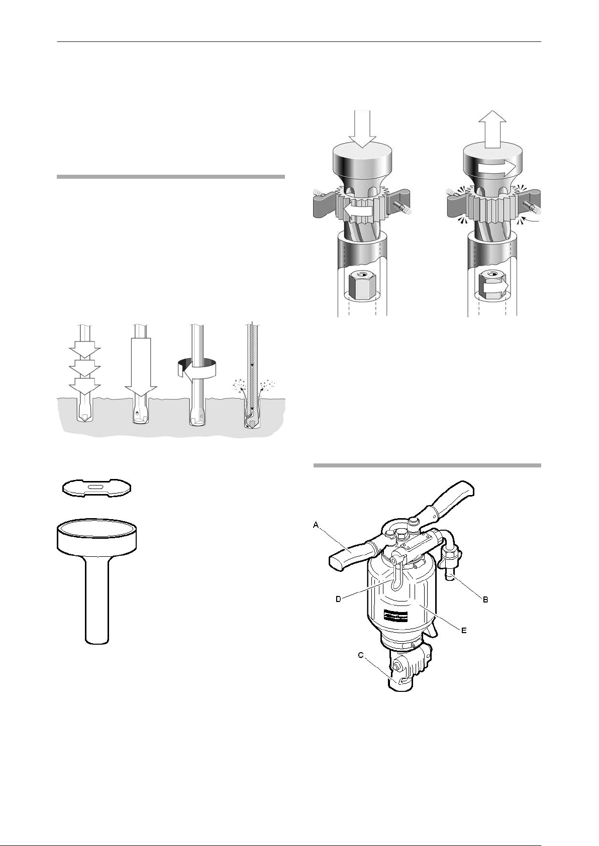
Working principle of a rock drill
FlushingRotationFeed forceImpact
Rotation mechanism
Return strokeImpact stroke
The drill steel is turned slightly with each blow by the
ratchet wheel rotation. The rotation is anti-clockwise
and is applied on the return stroke of the piston.
Control valve mechanism
The valve directs the air alternately from one side to
the other of the piston so that it moves up and down.
The piston transmits the energy through the drill steel
to the bottom of the hole.
Flushing
Flushing is ducted through a hole in the piston. This
means that flushing air is provided as soon as the
compressed air is switched on.
Main parts
BBD 12T/TS
Original instructions
13© 2010 Atlas Copco Construction Tools AB | No. 9800 0937 90 | 2010-01-01
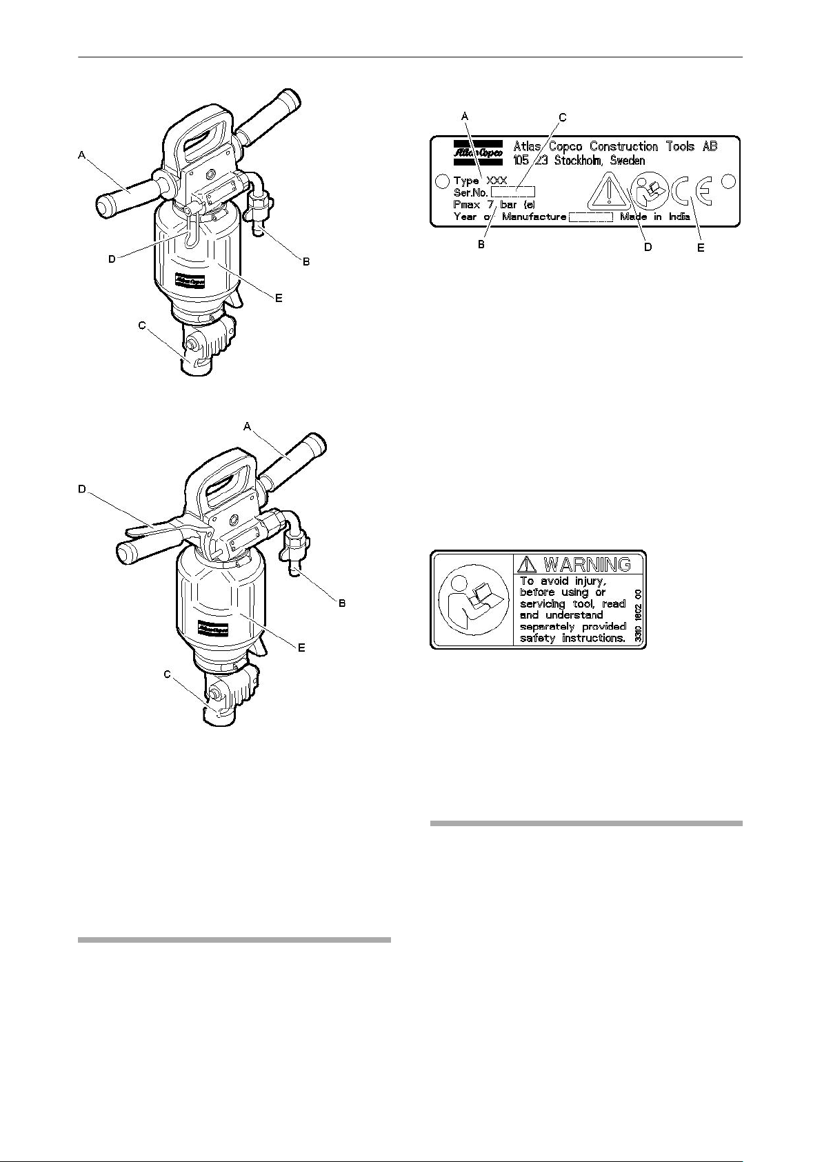
BBD 15E
BBD 12, 15Safety and operating instructions
Data plate
A. Machine type
B. Maximum permitted compressed air pressure
C. Serial number
D. The warning symbol together with the book
symbol means that the user must read the
safety and operating instructions before the
machine is used for the first time.
E. The CE symbol means that the machine is
EC-approved. See the EC declaration which
is delivered with the machine for more
information. If the CE symbol is missing, it
means that the machine is not EC-approved.
BBD 15ET
A. Handle
B. Air inlet nipple
C. Drill steel retainer
D. Throttle lever
E. Silencer (optional)
Labels
Safety label
To avoid injury, before using or servicing tool, read
and understand separately provided safety
instructions.
Installation
Unpacking the rock drill
Plastic guards
Before the rock drill is first used remove all the plastic
guards in the hose nipples, venting holes and rotation
chuck.
The machine is fitted with labels containing important
information about personal safety and machine
maintenance. The labels shall be in such condition
that they are easy to read. New labels can be ordered
from the spare parts list.
14
© 2010 Atlas Copco Construction Tools AB | No. 9800 0937 90 | 2010-01-01
Original instructions

Safety and operating instructionsBBD 12, 15
Assembly
BBD 12T/TS
1) Press the bushings and handles (A) onto each
side of the back head.
2) Secure the handles by tapping the spring pins
(B) into the back head.
Lubricate
After unpacking and installing the tool, pour a liberal
amount of lubrication oil in the air connection.
Hoses and connections
Methods to prevent freezing
Ice formation in the silencer can occur when the
ambient air temperature is 0–10°C (32-50 °F) and
the relative humidity is high.
The machine is designed to avoid the formation of
ice in the silencer. Despite this, under extreme
conditions ice can form in the silencer.
Take the following actions to further counteract the
risk of ice formation:
♦
Use Atlas Copco Rock Drill AIR-OIL as a lubricant.
♦
Use VAM 5A water separator.
If the rock drill freeze, never heat it to melt the ice.
Always let the ice thaw at room temperature.
Never pour methylated spirits or similar substances
into the rock drill, as they will interfere with the
lubrication and lead to increased wear.
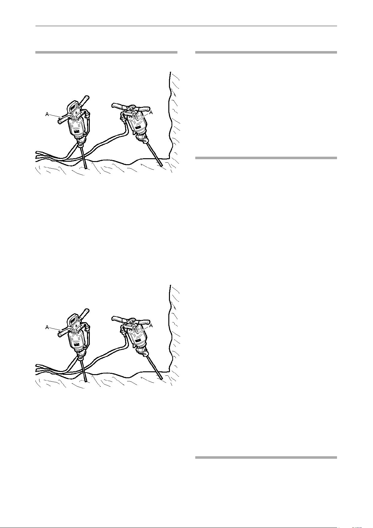
Connecting a water separator
The length of the air hose between the compressor
and the water separator must be such that the water
vapor is cooled and condenses in the hose before
reaching the water separator.
If the ambient temperature is below 0 °C (32 °F) the
hose must be short enough to prevent the water from
freezing before reaching the water separator.
A. Compressed air source
B. Water separator (optional)
C. Lubricator (optional)
D. Max. 3 meter compressed air hose between
the lubricator and the machine.
♦
Check that you are using the correct
recommended operating pressure, 6 bar (e).
♦
The maximum permissible air pressure, 7 bar (e),
must not be exceeded.
♦
Blow any impurities out of the compressed air hose
before connecting it to the machine.
♦
Select the correct dimension and length for the
compressed air hose. For hose lengths up to 30
meters, a hose with a minimum internal diameter
of 19 mm (3/4”) should be used. If the hose length
is between 30 and 100 meters, a hose with a
minimum internal diameter of 25 mm (1”) should
be used.
Lubrication
The rock drill is lubricated with oil mixed with
compressed air, which is taken to the parts that need
continuous lubrication. Oil is metered into the
compressed air using an Atlas Copco CLG 30
lubricator connected to the air line.
Use Atlas Copco Rock Drill AIR-OIL which is
specially developed for BBC, BBD and RH pneumatic
Rock drills. Rock Drill AIR-OIL is readily
biodegradable according to OECD 301 and has high
film strength that can withstand heavy loads. If Rock
Drill AIR-OIL is not available use a mineral-based air
tool oil with the properties recommended in the table
below.
Viscosity grade (ISO
3448)Temperature range (°C)
ISO VG 32-68-30 to 0
ISO VG 68-100-10 to +20
ISO VG 100-150+10 to +50
Original instructions
15© 2010 Atlas Copco Construction Tools AB | No. 9800 0937 90 | 2010-01-01

BBD 12, 15Safety and operating instructions
Pressure adjustment
Air pressure
Ensure that the compressor can deliver the required
air pressure of 4–6 bar to the tool.
1. High pressure causes rough operation and
excessive wear.
2. Low pressure results in a slow drilling speed.
Calibrate the correct air pressure
Use the Atlas Copco (9090 0550 80) pressure gauge
to check the air pressure when the rock drill is
running. The pressure should be measured close to
the inlet nipple. Maximum allowed working pressure
is 6 bar.
A dull drill steel will slow down the drilling speed and
overstrain the drill mechanism. When changing drill
steel make sure that the new one is the correct size
to follow your previous bore.
Before drilling, check that the flushing hole in the drill
steel is not blocked.
CAUTION Hot insertion tool
The tip of the insertion tool can become hot and
sharp when used. Touching it can lead to burns and
cuts.
► Never touch a hot or sharp insertion tool.
► Wait until the insertion tool has cooled down before
carrying out maintenance work.
NOTICE Never cool a hot insertion tool in water, it
can result in brittleness and early failure.
Fitting the drill steel
Whenever fitting the drill steel the following
instructions must be observed:
The pressure gauge is equipped with a needle which
is pressed into the hose to measure the pressure
inside.
Drill steel
WARNING Ejected insertion tool
If the tool retainer on the machine is not in a locked
position, the inserted tool can be ejected with force,
which can cause personal injury.
► Before changing the insertion tool, stop the
machine, switch off the compressed air supply
and bleed the machine by activating the start and
stop device.
Before fitting the drill steel
Check that the tool shank is of the correct size and
length for the chuck used. The shank must be clean
and the tool must be in good condition. Shanks which
are chipped, rounded, out of square or too hard on
the striking end will operate inefficiently and cause
premature piston failure.
Inspect the drill steel:
16
© 2010 Atlas Copco Construction Tools AB | No. 9800 0937 90 | 2010-01-01
Original instructions
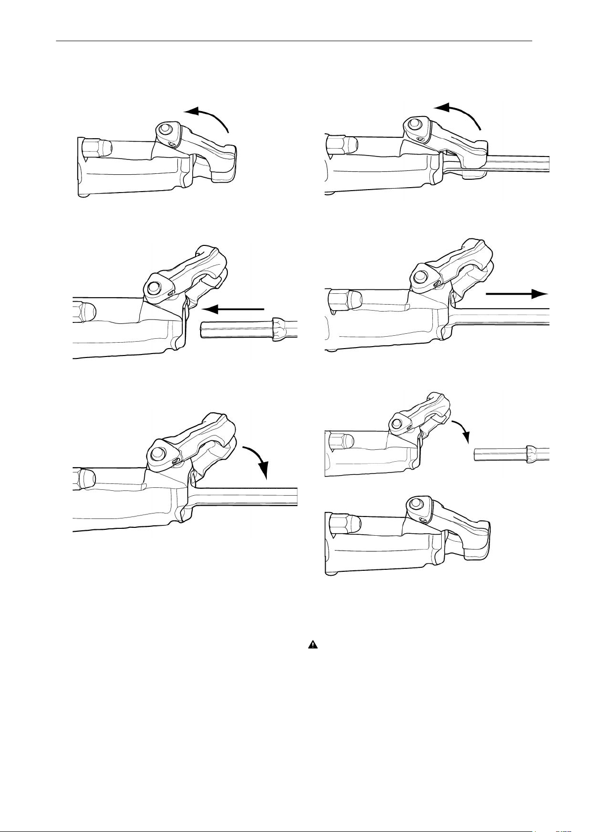
Safety and operating instructionsBBD 12, 15
1. Push the retainer outwards in the direction of the
arrow, until the front portion of the retainer is able
to accommodate the drill steel collar.
2. Insert the drill steel in the chuck.
1. Push the retainer outwards in the direction of the
arrow until the drill steel collar disengages from
the front of the retainer.
2. Pull the drill steel out.
3. When the drill bottoms, push back the retainer
to lock it.
Removing the drill steel
Whenever removing the drill steel the following
instructions must be observed:
3. Push back the retainer.
Operation
WARNING Involuntary start
Involuntary start of the machine may cause injury.
► Keep your hands away from the start and stop
device until you are ready to start the machine.
Original instructions
► Learn how the machine is switched off in the event
of an emergency.
► Stop the machine immediately in all cases of
power supply interruption.
17© 2010 Atlas Copco Construction Tools AB | No. 9800 0937 90 | 2010-01-01
Preparations before starting
Check the drilling equipment
♦
Check that all of the drilling equipment is in good
condition.
♦
Check that the impact surface of the drill steel
shank is flat, with no signs of wear.
♦
Make sure that the air inlet and exhaust ports are
free from obstructions.
♦
Check that the flushing holes in the drill steel and
drill bit are not blocked, and that the flushing air
and water flows through without obstruction.
♦
Make sure that the air filter (located in the air
nipple) is clean and not torn or distorted.
♦
Ensure that the fittings are tight and leak-proof.
DANGER Whipping air hose
A compressed air hose that comes loose can lash
around and cause personal injury or death
► Check that the compressed air hose and the
connections are not damaged.
BBD 12, 15Safety and operating instructions
BBD 15E
► Check that all compressed air connections are
properly attached.
Blow out the air hose
♦
Every day before using the drill, blow out the air
hose to clear it of accumulated dirt and moisture.
Fill the lubricator with oil
♦
Check that the chuck and drill steel shank are
always covered with a film of oil.
Controls
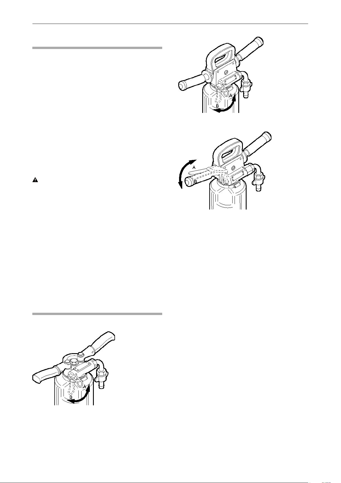
Throttle lever
BBD 15ET
The rock drill is equipped with a throttle lever for
regulating compressed air to the percussion
mechanism.
A. Throttle valve closed (stop position)
B. Throttle lever fully open
BBD 12T/TS
18
© 2010 Atlas Copco Construction Tools AB | No. 9800 0937 90 | 2010-01-01
Original instructions
Safety and operating instructionsBBD 12, 15
Start and stop
Starting the rock drill
1. Open the main valve for compressed air.
2. Align the rock drill so that the drill steel touches
the required collaring point.
3. Move the throttle lever (A) forward a little, which
will start the percussion and rotation.
Operating
Drilling
♦
Use protective shoes, gloves, helmet, ear
protectors and impact resistant eye protection with
side protection.
♦
Stand firmly and always hold the machine with
both hands.
♦
Hold the inserted tool firmly against the work
surface before starting the machine.
When taking a break
♦
During all breaks you must place the machine in
such a way that there is no risk for it to be
unintentionally started. Make sure to place the
machine on the ground, so that it can not fall.
♦
In the event of a longer break or when leaving the
workplace: Switch off the power supply and then
bleed the machine by activating the start and stop
device.
4. Collar the hole with reduced feed force.
5. Move the throttle lever (A) fully forward once the
drill steel has gained a secure footing in the rock.
Stopping the rock drill
1. Pull the throttle lever (A) backwards to the closed
position, this will stop the percussion and rotation.
Maintenance
Regular maintenance is a basic requirement for the
continued safe and efficient use of the machine.
Follow the maintenance instructions carefully.
♦
Before starting maintenance on the machine, clean
it in order to avoid exposure to hazard substances.
See “Dust and fume hazards”
♦
Use only authorised parts. Any damage or
malfunction caused by the use of unauthorised
parts is not covered by warranty or product liability.
♦
When cleaning mechanical parts with solvent,
comply with appropriate health and safety
regulations and ensure there is satisfactory
ventilation.
♦
For major service to the machine, contact your
nearest authorised workshop.
♦
After each service, check that the machine's
vibration level is normal. If not, contact your
nearest authorised workshop.
Original instructions
Differences between original
parts and pattern parts
When buying a part, the first thing to do is to verify
that the part is an Atlas Copco part. Most parts can
be identified.
19© 2010 Atlas Copco Construction Tools AB | No. 9800 0937 90 | 2010-01-01
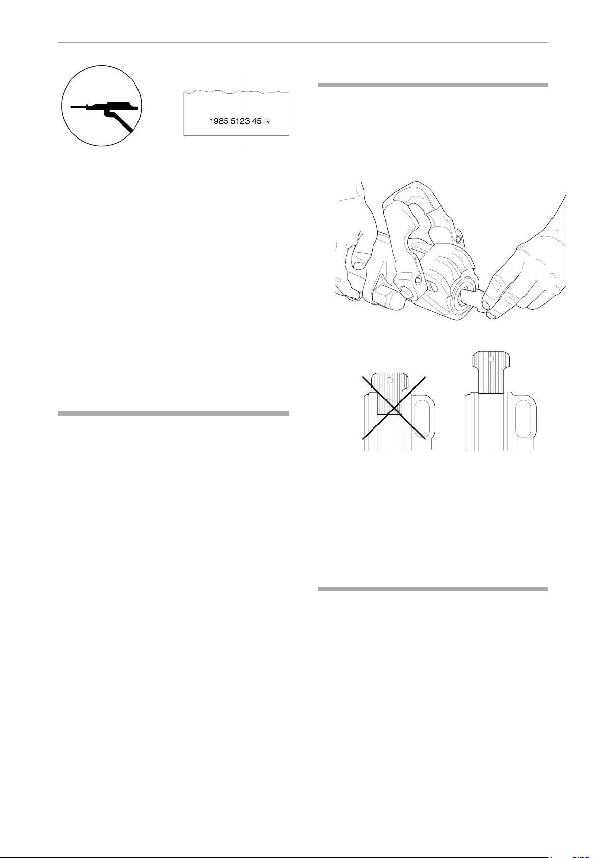
Rock drill parts are normally marked with a part
number and the Atlas Copco identity mark which is
a circle with a rock drill. In a few cases the part is
marked either with the circle only or the part number
only.
Rubber and plastic parts are not normally marked.
Competitors that copy our parts often mark major,
expensive parts. Some parts have only the part
number, but some of them also have an identity mark
in the form of the initials of the manufacturer's name.
Part numbers on the pattern parts are mostly
stamped by hand which results in irregularities. The
part numbers stamped by Atlas Copco are regular
and the individual figures are the same size. In
addition the depth of the figures and the spacing
between the figures in each group are the same.
BBD 12, 15Safety and operating instructions
Checking for wear
1. Check the wear in the chuck bushing using the
Atlas Copco (3091 0038 00) gauge (22 mm).
If the wear limit has been exceeded, the drill steel
shank will wear more quickly, or become
deformed. This will lead to stoppages and
increased drill-steel consumption.
Every day
Before undertaking any maintenance or changing
the insertion tool on pneumatic machines, always
switch off the air supply and bleed the machine by
depressing the start and stop device then disconnect
the air hose from the machine.
♦
Clean and inspect the machine and its functions
each day before the work commences.
♦
Conduct a general inspection for leaks and
damage.
♦
Check that the air inlet nipple is tightened and that
the claw coupling is free from damage.
♦
Check the function of the throttle handle. Make
sure that it moves freely up and down.
♦
Check the function of the retainer. Make sure that
it locks the drill steel.
♦
Change damaged parts immediately.
♦
Replace worn components in good time.
2. Check the hoses, couplings and controls for
leakage and damage.
3. Check that the rock drill is receiving enough
lubrication. Fill the lubricator if necessary.
4. Drain the water separator.
Periodic maintenance
After each operating period of approximately 100
working hours or three times a year the machine
must be dismantled and all parts be cleaned and
checked. This work must be performed by authorized
staff, trained for this task.
♦
Check the through bolts of the machine. Make
sure that they are tightened.
♦
If the machine is equipped with a silencer, check
for damage.
20
© 2010 Atlas Copco Construction Tools AB | No. 9800 0937 90 | 2010-01-01
Original instructions

Safety and operating instructionsBBD 12, 15
Tightening torque
BBD 12/15
A. Side bolt nut, 70 Nm (52 ft.lbf )
Damage patterns
Worn or broken parts must always be studied
carefully before they are replaced. They can give
important information about the condition of the drill
and about the way it is used and maintained.
CauseProblem
Steel parts are a bluish colour
microscopic fissures on the
wear surfaces
of bronze parts
The parts have been subjected
to excessive heat. This can be
caused by insufficient
lubrication or idling
See aboveSteel parts have small almost
See aboveIrregular cavities on the surface
Secondary damageCutting marks
Dirt inside the drill
Interior misalignment due to
uneven tension of the side
bolts
Disposal
A used machine must be treated and disposed of in
such a way that the greatest possible portion of the
material can be recycled and any negative influence
on the environment is kept as low as possible, and
in respect to local restrictions.
Storage
● Always oil the rock drill well, before you put it into
storage.
● Always store the machine in a clean and dry place.
● Make sure that no foreign matter enters the
machine.
● Protect the chuck using the plastic plug provided
with the machine. Alternatively, use a wooden plug
or a clean piece of cotton waste.
● In the case of long-term storage, pour a quantity
of oil directly into the rock-drill's air intake and then
turn on the air briefly. This will protect the machine
from corrosion.
Original instructions
21© 2010 Atlas Copco Construction Tools AB | No. 9800 0937 90 | 2010-01-01

Technical data
Machine data
BBD 12, 15Safety and operating instructions
Model
BBD 12T-01
BBD 12TS-01
BBD 15E
BBD 15ET
Piston bore
mm
(in.)Part numberModel
8311 0102 95BBD 12T-01
8311 0102 98BBD 12TS-01
8311 0104 02BBD 15E
8311 0104 10BBD 15E
8311 0104 12BBD 15ET
8311 0104 13BBD 15ET
45
(1.77)
45
(1.77)
45
(1.77)
45
(1.77)
45
(1.77)
45
(1.77)
Stroke length
mm
(in.)
40
(1.57)
40
(1.57)
40
(1.57)
40
(1.57)
40
(1.57)
40
(1.57)
Overall length
mm
(in.)
505
19.9
505
19.9
575
22.6
575
22.6
575
22.6
575
22.6
Weight
(lb)
11.1
(24.5)
12.1
(26.7)
15.5
(34.2)
15.5
(34.2)
15.6
(34.4)
15.6
(34.4)
Air consumption (6 bar)
l/s
(foot3/min )
(51)
(47)
(47)
(47)
Impact rate (6 bar)
Hz
4324
4222
4222
4222
Shank dimension
kg
Hole diameter
(0.94-1.34)
(0.94-1.34)
(0.67-1.14)
(0.67-1.14)
mm
(in.)
22 X 108
(⅞ x 4¼)
22 X 108
(⅞ x 4¼)
19 X 108
(3⁄4x 41⁄4)
22 X 108
(⅞ x 4¼)
19 X 108
(3⁄4x 41⁄4)
22 X 108
(⅞ x 4¼)
mm
(in.)
24-34
24-34
17-29
17-29
Noise and vibration declaration statement
Guaranteed sound power level Lw according to ISO 3744 in accordance with directive 2000/14/EC.
Sound pressure level Lp according to ISO 11203.
Vibration value A and uncertainty B determined according to ISO 20643. See table ”Noise and vibration data”
for the values of A, B, etc.
These declared values were obtained by laboratory type testing in accordance with the stated directive or
standards and are suitable for comparison with the declared values of other tools tested in accordance with
the same directive or standards. These declared values are not suitable for use in risk assessments and values
measured in individual work places may be higher. The actual exposure values and risk of harm experienced
by an individual user are unique and depend upon the way the user works, in what material the machine is
used, as well as upon the exposure time and the physical condition of the user, and the condition of the machine.
We, Atlas Copco Construction Tools AB, cannot be held liable for the consequences of using the declared
values, instead of values reflecting the actual exposure, in an individual risk assessment in a work place situation
over which we have no control.
This tool may cause hand-arm vibration syndrome if its use is not adequately managed. An EU guide to managing
hand-arm vibration can be found at http://www.humanvibration.com/EU/VIBGUIDE.htm
We recommend a programme of health surveillance to detect early symptoms which may relate to vibration
exposure, so that management procedures can be modified to help prevent future impairment.
22
© 2010 Atlas Copco Construction Tools AB | No. 9800 0937 90 | 2010-01-01
Original instructions

Noise and vibration data
Safety and operating instructionsBBD 12, 15
VibrationNoise
Declared valuesDeclared values
Three axes valuesSound powerSound pressure
EN ISO 206432000/14/ECISO 11203
Accessories
Lp
r=1m dB(A) rel
20µPaModel
Lw
guaranteed dB(A) rel
1pW
A
m/s2value
B
m/s2spreads
2.116.0116103BBD 12T-01
2.116.011198BBD 12TS-01
1.27.011097BBD 15E
1.27.011097BBD 15ET
Part numberQuantityRemarkDescription
8202 5102 391For both mineral and synthetic oilCLG 30, European type
8202 5102 051For mineral oilBLG 30, European type
8092 0110 581Airflow <50 l/s (106 ft3/min)VAM 01, European type
8092 0110 821Airflow <120 l/s (254 ft3/min)VAM 5A, European type
9030 2047 00120 mm (3⁄4")Rubber hose, pre-mounted
9030 2115 00120 mm (3⁄4")X-LITE flat hose, universal
8099 0201 0414 lRock Drill AIR-OIL
8099 0201 10110 lRock Drill AIR-OIL
Original instructions
23© 2010 Atlas Copco Construction Tools AB | No. 9800 0937 90 | 2010-01-01

BBD 12, 15Safety and operating instructions
EC Declaration of Conformity
EC Declaration of Conformity (EC Directive 2006/42/EC)
We, Atlas Copco Construction Tools AB, hereby declare that the machines listed below conform to the provisions
of EC Directive 2006/42/EC (Machinery Directive), and the harmonised standards mentioned below.
Pmax (bar)Part numberRock drills
78311 0102 95BBD 12T-01
78311 0102 98BBD 12TS-01
78311 0104 02BBD 15E
78311 0104 10BBD 15E
78311 0104 12BBD 15ET
78311 0104 13BBD 15ET
Technical Documentation authorised representative:
Erik Sigfridsson
Atlas Copco Construction Tools AB
Dragonvägen 2
Kalmar
General Manager:
Erik Sigfridsson
Manufacturer:
Atlas Copco Construction Tools AB
105 23 Stockholm
Sweden
Place and date:
Kalmar, 2010-01-01
24
© 2010 Atlas Copco Construction Tools AB | No. 9800 0937 90 | 2010-01-01
Original instructions


BBD 12, 15Sommaire
FRANÇAIS
Sommaire
Introduction. . . . . . . . . . . . . . . . . . . . . . . . . . . . . . . . . . . . . . . . . . . . . . . . . . . . . . . . . . . . . . . . . . . . . . . 29
À propos des prescriptions de sécurité et des instructions pour l'opérateur. . . . . . . . . . . 29
Consignes de sécurité. . . . . . . . . . . . . . . . . . . . . . . . . . . . . . . . . . . . . . . . . . . . . . . . . . . . . . . . . . . . . 30
Indications de sécurité. . . . . . . . . . . . . . . . . . . . . . . . . . . . . . . . . . . . . . . . . . . . . . . . . . . . . . . . . . 30
Précautions et qualifications du personnel. . . . . . . . . . . . . . . . . . . . . . . . . . . . . . . . . . . . . . . 30
Équipement de protection du personnel. . . . . . . . . . . . . . . . . . . . . . . . . . . . . . . . . . . . . . . . . . 30
Drogues, alcool ou médicaments. . . . . . . . . . . . . . . . . . . . . . . . . . . . . . . . . . . . . . . . . . . . . . . . 30
Installation, précautions. . . . . . . . . . . . . . . . . . . . . . . . . . . . . . . . . . . . . . . . . . . . . . . . . . . . . . . . . 30
Fonctionnement, précautions. . . . . . . . . . . . . . . . . . . . . . . . . . . . . . . . . . . . . . . . . . . . . . . . . . . . 31
Maintenance, précautions. . . . . . . . . . . . . . . . . . . . . . . . . . . . . . . . . . . . . . . . . . . . . . . . . . . . . . . 36
Stockage, précautions. . . . . . . . . . . . . . . . . . . . . . . . . . . . . . . . . . . . . . . . . . . . . . . . . . . . . . . . . . 36
Vue d'ensemble. . . . . . . . . . . . . . . . . . . . . . . . . . . . . . . . . . . . . . . . . . . . . . . . . . . . . . . . . . . . . . . . . . . 37
Conception et fonctionnement. . . . . . . . . . . . . . . . . . . . . . . . . . . . . . . . . . . . . . . . . . . . . . . . . . . 37
Principe de fonctionnement d'un marteau perforateur. . . . . . . . . . . . . . . . . . . . . . . . . . . . . . 37
Mécanisme de la vanne de commande. . . . . . . . . . . . . . . . . . . . . . . . . . . . . . . . . . . . . . . . . . 37
Mécanisme de rotation. . . . . . . . . . . . . . . . . . . . . . . . . . . . . . . . . . . . . . . . . . . . . . . . . . . . . . . . 37
Rincage. . . . . . . . . . . . . . . . . . . . . . . . . . . . . . . . . . . . . . . . . . . . . . . . . . . . . . . . . . . . . . . . . . . . . 37
Principales pièces. . . . . . . . . . . . . . . . . . . . . . . . . . . . . . . . . . . . . . . . . . . . . . . . . . . . . . . . . . . . . . 37
Étiquettes. . . . . . . . . . . . . . . . . . . . . . . . . . . . . . . . . . . . . . . . . . . . . . . . . . . . . . . . . . . . . . . . . . . . . . 38
Plaque signalétique. . . . . . . . . . . . . . . . . . . . . . . . . . . . . . . . . . . . . . . . . . . . . . . . . . . . . . . . . . . 38
Étiquette de sécurité. . . . . . . . . . . . . . . . . . . . . . . . . . . . . . . . . . . . . . . . . . . . . . . . . . . . . . . . . . 38
Pose. . . . . . . . . . . . . . . . . . . . . . . . . . . . . . . . . . . . . . . . . . . . . . . . . . . . . . . . . . . . . . . . . . . . . . . . . . . . . . 38
Réception et déballage du marteau perforateur. . . . . . . . . . . . . . . . . . . . . . . . . . . . . . . . . . . 38
Protections en plastique. . . . . . . . . . . . . . . . . . . . . . . . . . . . . . . . . . . . . . . . . . . . . . . . . . . . . . . 38
Assemblage. . . . . . . . . . . . . . . . . . . . . . . . . . . . . . . . . . . . . . . . . . . . . . . . . . . . . . . . . . . . . . . . . . 39
Lubrification. . . . . . . . . . . . . . . . . . . . . . . . . . . . . . . . . . . . . . . . . . . . . . . . . . . . . . . . . . . . . . . . . . 39
Flexibles et connexions. . . . . . . . . . . . . . . . . . . . . . . . . . . . . . . . . . . . . . . . . . . . . . . . . . . . . . . . . 39
Mesures de prévention du gel. . . . . . . . . . . . . . . . . . . . . . . . . . . . . . . . . . . . . . . . . . . . . . . . . . . 39
Branchement d'un séparateur d'eau. . . . . . . . . . . . . . . . . . . . . . . . . . . . . . . . . . . . . . . . . . . . . . 39
Graissage. . . . . . . . . . . . . . . . . . . . . . . . . . . . . . . . . . . . . . . . . . . . . . . . . . . . . . . . . . . . . . . . . . . . . . 39
Réglage de pression. . . . . . . . . . . . . . . . . . . . . . . . . . . . . . . . . . . . . . . . . . . . . . . . . . . . . . . . . . . . 40
Pression d'air. . . . . . . . . . . . . . . . . . . . . . . . . . . . . . . . . . . . . . . . . . . . . . . . . . . . . . . . . . . . . . . . . 40
Étalonner la pression d'air correcte. . . . . . . . . . . . . . . . . . . . . . . . . . . . . . . . . . . . . . . . . . . . . . 40
Fleuret. . . . . . . . . . . . . . . . . . . . . . . . . . . . . . . . . . . . . . . . . . . . . . . . . . . . . . . . . . . . . . . . . . . . . . . . . 40
Avant de fixer le fleuret. . . . . . . . . . . . . . . . . . . . . . . . . . . . . . . . . . . . . . . . . . . . . . . . . . . . . . . . 40
Fixation du fleuret. . . . . . . . . . . . . . . . . . . . . . . . . . . . . . . . . . . . . . . . . . . . . . . . . . . . . . . . . . . . . 40
Retrait du fleuret. . . . . . . . . . . . . . . . . . . . . . . . . . . . . . . . . . . . . . . . . . . . . . . . . . . . . . . . . . . . . . 41
Utilisation. . . . . . . . . . . . . . . . . . . . . . . . . . . . . . . . . . . . . . . . . . . . . . . . . . . . . . . . . . . . . . . . . . . . . . . . . 41
Opérations à effectuer avant la mise en service. . . . . . . . . . . . . . . . . . . . . . . . . . . . . . . . . . . 42
Contrôler l'équipement de forage. . . . . . . . . . . . . . . . . . . . . . . . . . . . . . . . . . . . . . . . . . . . . . . . 42
Purger le flexible à air. . . . . . . . . . . . . . . . . . . . . . . . . . . . . . . . . . . . . . . . . . . . . . . . . . . . . . . . . 42
Remplissez le lubrificateur d'huile. . . . . . . . . . . . . . . . . . . . . . . . . . . . . . . . . . . . . . . . . . . . . . . 42
Commandes. . . . . . . . . . . . . . . . . . . . . . . . . . . . . . . . . . . . . . . . . . . . . . . . . . . . . . . . . . . . . . . . . . . 42
Levier de commande. . . . . . . . . . . . . . . . . . . . . . . . . . . . . . . . . . . . . . . . . . . . . . . . . . . . . . . . . . 42
Marche/arrêt. . . . . . . . . . . . . . . . . . . . . . . . . . . . . . . . . . . . . . . . . . . . . . . . . . . . . . . . . . . . . . . . . . . 43
Démarrage du marteau perforateur. . . . . . . . . . . . . . . . . . . . . . . . . . . . . . . . . . . . . . . . . . . . . . 43
Arrêt du marteau perforateur. . . . . . . . . . . . . . . . . . . . . . . . . . . . . . . . . . . . . . . . . . . . . . . . . . . 43
Utilisation. . . . . . . . . . . . . . . . . . . . . . . . . . . . . . . . . . . . . . . . . . . . . . . . . . . . . . . . . . . . . . . . . . . . . . 43
Forage. . . . . . . . . . . . . . . . . . . . . . . . . . . . . . . . . . . . . . . . . . . . . . . . . . . . . . . . . . . . . . . . . . . . . . 43
Lors des pauses. . . . . . . . . . . . . . . . . . . . . . . . . . . . . . . . . . . . . . . . . . . . . . . . . . . . . . . . . . . . . . . . 43
26
© 2010 Atlas Copco Construction Tools AB | No. 9800 0937 90 | 2010-01-01
Instructions d’origine

SommaireBBD 12, 15
Maintenance. . . . . . . . . . . . . . . . . . . . . . . . . . . . . . . . . . . . . . . . . . . . . . . . . . . . . . . . . . . . . . . . . . . . . . 43
Différences entre les pièces d'origine et les pièces copiées. . . . . . . . . . . . . . . . . . . . . . . . 44
Chaque jour. . . . . . . . . . . . . . . . . . . . . . . . . . . . . . . . . . . . . . . . . . . . . . . . . . . . . . . . . . . . . . . . . . . . 44
Contrôle de l'usure. . . . . . . . . . . . . . . . . . . . . . . . . . . . . . . . . . . . . . . . . . . . . . . . . . . . . . . . . . . . . 44
Maintenance périodique. . . . . . . . . . . . . . . . . . . . . . . . . . . . . . . . . . . . . . . . . . . . . . . . . . . . . . . . . 45
Couple de serrage. . . . . . . . . . . . . . . . . . . . . . . . . . . . . . . . . . . . . . . . . . . . . . . . . . . . . . . . . . . . . . 45
Types de dégâts. . . . . . . . . . . . . . . . . . . . . . . . . . . . . . . . . . . . . . . . . . . . . . . . . . . . . . . . . . . . . . . . 45
Stockage. . . . . . . . . . . . . . . . . . . . . . . . . . . . . . . . . . . . . . . . . . . . . . . . . . . . . . . . . . . . . . . . . . . . . . . . . 45
Destruction d'une machine usagée. . . . . . . . . . . . . . . . . . . . . . . . . . . . . . . . . . . . . . . . . . . . . . . . . 45
Caractéristiques techniques. . . . . . . . . . . . . . . . . . . . . . . . . . . . . . . . . . . . . . . . . . . . . . . . . . . . . . . . 46
Caractéristiques de la machine. . . . . . . . . . . . . . . . . . . . . . . . . . . . . . . . . . . . . . . . . . . . . . . . . . 46
Énoncé déclaratif sur les vibrations et le bruit. . . . . . . . . . . . . . . . . . . . . . . . . . . . . . . . . . . . 46
Données relatives au bruit et aux vibrations. . . . . . . . . . . . . . . . . . . . . . . . . . . . . . . . . . . . . . 47
Accessoires. . . . . . . . . . . . . . . . . . . . . . . . . . . . . . . . . . . . . . . . . . . . . . . . . . . . . . . . . . . . . . . . . . . . 47
Déclaration CE de conformité. . . . . . . . . . . . . . . . . . . . . . . . . . . . . . . . . . . . . . . . . . . . . . . . . . . . . . 48
Déclaration CE de conformité (Directive 2006/42/CE). . . . . . . . . . . . . . . . . . . . . . . . . . . . . . 48
Instructions d’origine
27© 2010 Atlas Copco Construction Tools AB | No. 9800 0937 90 | 2010-01-01


BBD 12, 15
Prescriptions de sécurité et instructions pour
l’opérateur
Introduction
Nous vous remercions d'avoir choisi un produit Atlas Copco. Depuis 1873,
nous nous efforçons de trouver des solutions pertinentes et adaptées aux
besoins de nos clients. Au fil des ans, nous avons développé des produits
innovants et ergonomiques qui contribuent à l'amélioration et à la rationalisation
du travail quotidien de nos clients.
Atlas Copco dispose d'un solide réseau de distribution et de service
après-vente, constitué de centres de clientèle et de distributeurs, partout dans
le monde. Nos experts sont des professionnels formés, bénéficiant d'un
savoir-faire global en termes de produits et d'applications. Aux quatre coins
du monde, nous sommes en mesure d'offrir le soutien et l'expérience requis
pour garantir à nos clients une efficacité optimale et continue de leur activité.
Pour plus d’informations, veuillez consulter le site Web suivant :
www.atlascopco.com
Atlas Copco Construction Tools AB
105 23 Stockholm
Sweden
À propos des prescriptions de sécurité
et des instructions pour l'opérateur
Le but des instructions est de vous apprendre à utiliser le marteau perforateur
d’une manière efficace et en toute sécurité. Les instructions vous donnent
également des conseils et vous indiquent comment effectuer la maintenance
de routine du marteau perforateur.
Vous devez lire ces instructions attentivement et les comprendre avant d'utiliser
le marteau perforateur pour la première fois.
Instructions d’origine
29© 2010 Atlas Copco Construction Tools AB | No. 9800 0937 90 | 2010-01-01

l’opérateur
BBD 12, 15Prescriptions de sécurité et instructions pour
Consignes de sécurité
Il convient de lire et d'assimiler les Prescriptions de
sécurité et des instructions pour l'opérateur avant
toute installation, utilisation, réparation, entretien ou
remplacement d'accessoire sur la machine, afin de
minimiser le risque de blessures graves ou de
dommages pouvant entraîner la mort.
Affichez les Prescriptions de sécurité et instructions
pour l'opérateur sur les différents sites de travail ;
faites en des copies pour les employés et
assurez-vous que chaque personne concernée a
bien lu les Prescriptions de sécurité et instructions
pour l'opérateur, avant d'utiliser ou d'intervenir sur
la machine.
En outre, l'opérateur ou l'employeur doit évaluer les
risques spécifiques pouvant survenir à la suite de
chaque utilisation de la machine.
Indications de sécurité
Les indications de sécurité Danger, Attention et
Prudence ont les sens suivants :
DANGER
ATTENTION
PRUDENCE
Indique une situation
dangereuse qui, si elle n'est
pas évitée, terminera par
provoquer la mort ou des
blessures graves.
Indique une situation
dangereuse qui, si elle n'est
pas évitée, est de susceptible
de provoquer la mort ou des
blessures graves.
Indique une situation
dangereuse qui, si elle n'est
pas évitée, est de susceptible
de provoquer des blessures
mineures à modérées.
Équipement de protection du personnel
Utilisez toujours un équipement de protection
individuelle homologué. Les opérateurs et toutes
autres personnes séjournant sur la zone de travail
doivent porter un équipement de protection
individuelle, incluant au minimum :
● Casque de protection
● Protections auditives
● Protecteurs des yeux résistants aux chocs avec
protection latérale
● Appareil de protection respiratoire, le cas échéant
● Gants de protection
● Bottes de protection adaptées
● Salopette de travail appropriée ou vêtement
similaire (serré) qui recouvre les bras et les
jambes.
Drogues, alcool ou médicaments
AVERTISSEMENT Drogues, alcool ou
médicaments
Les drogues, l'alcool ou les médicaments risquent
d'avoir un effet négatif sur votre jugement et votre
capacité de concentration. De mauvaises réactions
et des évaluations incorrectes peuvent entraîner des
accidents graves, voire la mort.
► N'utilisez jamais la machine lorsque vous êtes
fatigué(e) ou sous l'influence de drogues, de
l'alcool ou de médicaments.
► L'utilisation de la machine par une personne sous
l'influence de drogues, de l'alcool ou de
médicaments est strictement interdite.
Installation, précautions
Précautions et qualifications
du personnel
Seules des personnes qualifiées ou formées peuvent
utiliser ou procéder à l'entretien de la machine. Elles
doivent être physiquement aptes à manipuler le
volume, le poids et la puissance de l'outil. Utilisez
toujours votre jugement et votre bon sens.
30
© 2010 Atlas Copco Construction Tools AB | No. 9800 0937 90 | 2010-01-01
DANGER Coup de fouet d'un flexible
pneumatique
Un flexible d'air comprimé qui se détache risque de
fouetter dans tous les sens et de provoquer des
dommages corporels ou la mort. Pour réduire ce
risque :
► Vérifiez que le flexible d'air comprimé et les
raccords ne sont pas endommagés. Les remplacer
si nécessaire.
► Vérifiez que les raccords d'air comprimé sont
correctement fixés.
► Ne jamais porter une machine pneumatique par
le flexible d'air.
Instructions d’origine
 Loading...