

Atlas Copco Air Contact Hardware Manual
1
ELEKTRONIKON® MKIV
AIR CONTACT GSM-GPRS modem
EU Part.Nr. 1900 0711 XX (65-70)
US Part.Nr. 1900 0711 XX (75-80)
Hardware Manual
Version 1.4
The version of the entire document is increased on the occasion of each modification.
Modifications are listed in the chapter “Version History“.
Air Contact Hardware Manual
2
All rights reserved. This document remains the intellectual property of ATLAS COPCO. No part of this
document may be reproduced, transmitted, transcribed, stored in a retrieval system, in any form or by any
means, electronic, mechanical, optical, manual or otherwise, without permission in writing of ATLAS
COPCO. Transmission on to third parties is only allowed if the explicit permission of ATLAS COPCO is
obtained beforehand.
ATLAS COPCO declines all claims for damages which arises from the application of information that may
be wrong or inadequate or missing in this document.
ATLAS COPCO reserves the right to change this document complete or partially .
All brand names and product names are trade marks or registered trade marks of the proprietors of the
respective titles.
IMPORTANT REMARKS
Changes or modifications not expressly approved by the party responsible for compliance could void the user’s
authority to operate the equipment.
Symbols for attention notes
Warning for general dangers.
Warning for dangerous electrical voltage.
ESD endangered devices. Housings and connections are only to be opened from
trained persons!
Remarks.

Air Contact Hardware Manual
3
Table of contents Page
1
Introduction 4
1.1 Preface 4
1.2 Product Description 4
1.3 FCC 4
2 Glossary 5
3 Features 6
4 Function Description 7
4.1 General 7
4.2 Digital Input 7
4.3 HMI 7
4.4 Nonvolatile RAM functionality 8
4.5 CAN-Bus 8
4.6 RS232 9
4.7 GSM Modem 9
5 Microcontroller 10
5.1 Block diagram 11
5.2 Memory-Layout 12
6 GSM components 14
6.1 EU GSM modem module 14
6.2 US GSM/GPRS modem module 15
6.3 Antenna 15
7 Technical Data 16
8 Pin Assignment 19
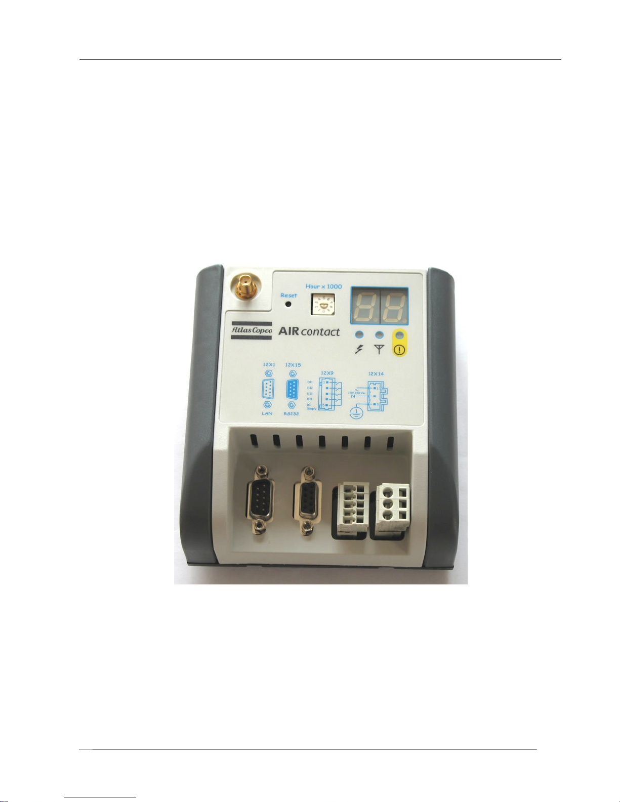
9 Housing 21
9.1 Front View 21
9.2 Views 22
9.3 The GSM module location 23
9.4 The antenna placement 23
10 Battery Replacement 24
11 IMEI code 25
12 General Operation 26
13 Versions history 27

Air Contact Hardware Manual
4
1 Introduction
1.1 Preface
This manual gives all the main information relevant the Air Contact module for Atlas Copco compressors.
It provides also preliminary hardware information for the system programmer. The manual contains
interconnections, technical data and mounting requirements.
1.2 Product Description
This manual describes the main part of the AIR CONTACT modem GSM/GPRS module.
The main features of the product are the following:
1. send some diagnostic SMS message to GSM telephone network on digital input events.
2. establish a data modem connection over the GSM network.
3. send a special diagnostic SMS message in case of loss of main power.
4. send a special diagnostic SMS message in case of backup battery replacement service
1.3 FCC
This device complies with Part 15 of the FCC Rules. Operation is subject to the following two
conditions (1) this device may not cause harmful interference and (2) this device must accept any
interference received, including interference that may cause undesired operation.
IMPORTANT NOTE:
FCC Radiation Exposure Statement:
This equipment complies with FCC radiation exposure limits set forth for an uncontrolled
environment. This equipment should be installed and operated with minimum distance of 20cm
between the radiator and your body.
This transmitter must not be co-located or operating in conjunction with any other antenna or
transmitter.

Air Contact Hardware Manual
5
2 Glossary
ELEKTRONIKON® MkIV Compressor control electronic of the fourth generation.
CPU Control Process Unit.
PCB Printed Circuit Board
HMI Human Machine Interface
Main Controller Main control part of each compressor. Contains MMI, I/O’s
IC Integrated circuit.
EMC Electromagnetic Compatibility
LED Light Emitting Diode
Flash EPROM Erasable Programmable Read Only Memory. Flash types allows an
electronic erase.
SRAM Static Random Access Memory

Air Contact Hardware Manual
6
3 Features
Main Parts
• HMI
o 2 x 7-segment LED display
o 1 push button
o 1 Service hours rotary switch with 10 positions
o status LEDs
o 1 x CAN address dip switch
• 512 kByte Flash EPROM
• 128 kByte SRAM
• 1 kbytes E2PROM emulated in a 8Kbytes Flash sector
• 1 RS232 serial Line
• 1 CAN BUS serial line (not optocoupled)
• Digital Inputs to be connected to a free contact
• Antenna with magnetic base, 5m coaxial cable, SMA right angle connector
• 1 GSM dual band AT modem with rechargeable LI-ION battery.
Optionally a GSM/GPRS dual band AT modem could be mounted
Power Supply: wide range voltage (100 ÷ 240 VAC)

Air Contact Hardware Manual
7
4 Function Description
4.1 General
The Main Controller is supplied with nominal 115/230 VAC.
The device has not a fuse in the power supply line. A fuse T1AH, 250V (slow-blow) CSA
certified and UL recognized has to be provided externally as described in paragraph 10.1.
Warning, dangerous electrical voltage can be at the connector. Never touch connections,
when the device is running.
Protective earth PE has to be connected.
The Main Controller contain electrostatically sensitive components:
Prior to assembly and service operations, the personnel must be free of electrostatic charge,
e.g. by touching the PE fixing screw or other grounded metal surfaces in the control cabinet.
4.2 Digital Input
The controller supplies a ground, which could be returned to a digital input over an external voltage free contact..
• Note, that the digital inputs are not isolated.
• When relay contacts are used, they generate typical 20ms bounces. The filtering of these
signals has been done in software.
4.3 HMI
The HMI (Human Machine Interface) consist of:
• 2 x 7-segment LED display
• 1 push button
• 3 LEDs
• 1 x selector rotary dip switch
• accessible SIM card holder
• Customer specific adhesive lexan front foil
4.3.1 LED-Display
The LED-display provided for the Air Contact is a simple 2 digit 7-segment LED. It is used mainly to show
the time left in service hours. One digit is for the thousands of hours and the other one for the hundreds
of hours. Some other diagnostic numeric codes could be also showed.
Parameter Value
dimensions 16 x 26 mm
Digits 2 x 7segment
Color Red Led Segments

Air Contact Hardware Manual
8
4.3.2 Push button
The module has 1 push button. It is mechanically protected from accidental pushing. It is used to reset the
service hours counter.
4.3.3 Leds
Three LEDs are mounted on the PCB, visible to the operator through dedicated holes in the front panel
and have the function to indicate machine status. One LED is controlled by microcontroller, one LED is
directly controlled by modem AT interface and one LED is used to indicate power on.
4.3.4 Switches
One rotary selector switch with 10 positions is provided in the design to adjust the service time hours.
The switch is accessible from outside and can be turned with a screw driver. Service Time hours from
1000 up to 9000 are possible. The switch is used to select the thousands of hours.
4.3.5 Sim Card Holder
A SIM card holder is provided in the design to insert and change the SIM card. The SIM card holder is
accessible from outside the front panel under a plastic cap removable by service personnel.
4.3.6 Lexan adhesive front foil
A coulored custom specific adhesive front foil in Lexan material is provided on the front panel to show
connectors code and labels indication.
4.4 Nonvolatile RAM functionality
Like the Main MkIV Controllers the Air Contact GSM module has an Nonvolatile RAM feature to save data
before a power off occurs. The concept behind is the same. If the power supply falls below the specified
minimum voltage an interrupt occurs. From now on the CPU saves the specific data in the Flash EPROM.
4.5 CAN-Bus
The C164CI has an integrated On-Chip CAN unit according the CAN specification V2.0 part B. This
module handles the completely autonomous transmission and reception of CAN telegrams. That means,
once the transmit buffer has written or the receive buffer is empty no CPU time is required. The CAN unit
can receive and transmit standard frames with 11-bit identifier as well as extended frames with 29-bit
identifier. Which kind of configuration will be used depends on the software protocol. The baudrate is
programmable in a wide range, but only standards will be implemented.
Switches:
One 8 dip switch selector is provided in the design to set the CAN-Bus node number.
The switches are accessible from outside. Node numbers from 1 up to 31 are possible.
Air Contact Hardware Manual
9
8 x Dip Switch CANbus Node Address
Note: the address dip switch is read only at power on of the supply
Example of address selection:
CANbus Node Address = 1, the Dip switch configuration is:
4.6 RS232
This interface is useful for point to point communication at low speed. The signals are referred to ground.
In Air Contact configuration the externally accessible RS232C serial is used to connect directly to Modem
serial interface.
• The pin assignment is compatible with a DCE connection
• RS232C is not suitable for high speed and long distance.
• hardware handshake is provided.
An internal electronic switch is used to connect alternalively the Modem serial connection to
microcontroller serial port (referenced as PORT1) or to the DB9 connector serial port (referenced as
PORT2).
4.7 GSM Modem
A mountable on PCB commercial modem module is used to integrate a GSM telephone connection to the
electronic stand alone controller. The antenna is external. Optionally a compatible GSM/GPRS
commercial modem module could be soldered on the same PCB place as alternative to the standard
GSM modem.
Dip Swich Number Function
1,2,3 Reserved to Modem functionality
4,5,6,7,8 LAN address selector (Binary Code, valid = 1 to 31)
Dip Sw
number
1 2 3 4 5 6 7 8
ON
x
OFF
x x x x x x x
 Loading...