

Atlas Copco ACTA 4000, ACTA 3000 User Manual
User Guide
ACTA 4000
Also valid for ACTA 3000
Atlas Copco Tools and Assembly Systems
9836 4171 01
2008-12

Copyright Atlas Copco Tools and Assembly Systems
Note! This manual can be altered without further notice.
For further information log in to Atlas Copco www.atlascopco.com

ACTA 4000 User Guide Contents
9836 4171 01 2008-12 3 (136)
Contents
Contents.........................................................................................................................3
1 System overview ...................................................................................................7
1.1 ACTA functionality ....................................................................................................................7
1.1.1 ACTA Basic............................................................................................................................ 8
1.1.2 ACTA Quality Control............................................................................................................. 8
1.1.3 ACTA Advanced Analysis ...................................................................................................... 8
1.2 ToolsTalk QAT ..........................................................................................................................8
1.3 How to use this guide................................................................................................................9
1.3.1 Revision History ................................................................................................................... 10
2 Interface ............................................................................................................... 11
2.1 Front panel..............................................................................................................................11
2.1.1 Display ................................................................................................................................. 12
2.1.2 Menu Blocks......................................................................................................................... 13
2.1.3 Pull-up menus ...................................................................................................................... 13
2.1.4 Input dialog boxes ................................................................................................................ 14
3 Getting started.....................................................................................................17
3.1 Out of the Box .........................................................................................................................17
3.2 Installation ...............................................................................................................................17
3.2.1 Installing software ................................................................................................................ 18
3.3 Startup.....................................................................................................................................19
3.4 Using Quick programming ......................................................................................................19
3.4.1 Measuring tools.................................................................................................................... 20
3.4.2 Measuring controlled tools with synchronization .................................................................. 20
3.5 Connecting ToolsTalk QAT.....................................................................................................22
4 Programming ACTA............................................................................................23
4.1 View ........................................................................................................................................25
4.2 Print menu...............................................................................................................................26
4.3 Quick Programming (Q.Prog.) ................................................................................................29
4.3.1 Quick programming tools ..................................................................................................... 30
4.3.2 Synchronize ......................................................................................................................... 30
4.3.3 ISO 5393.............................................................................................................................. 31
4.3.4 Measuring tools according to ISO 5393 ............................................................................... 31
4.4 Statistics (Stat.) .......................................................................................................................34
4.4.1 All tightening......................................................................................................................... 35
4.4.2 Statistics torque, Statistics angle and Statistics pulse.......................................................... 36
4.4.3 History.................................................................................................................................. 37
4.4.4 Manual Input ........................................................................................................................ 39
4.5 Configuration (Conf.)...............................................................................................................40
4.5.1 Interface ............................................................................................................................... 41
4.5.2 Calibration ............................................................................................................................ 47
4.5.3 Diagnostics........................................................................................................................... 47
4.5.4 Transducer memory ............................................................................................................. 51
4.5.5 Communication .................................................................................................................... 52
4.5.6 Product information .............................................................................................................. 53
4.5.7 Options................................................................................................................................. 53
4.6 Database (Datab)....................................................................................................................54
4.6.1 New tool ............................................................................................................................... 54

Contents ACTA 4000 User Guide
4 (136) 2008-12 9836 4171 01
4.6.2 Select Tool............................................................................................................................54
4.6.3 Delete Tool ...........................................................................................................................55
4.6.4 Clear all measurements ........................................................................................................55
4.6.5 Backup tool ...........................................................................................................................55
4.6.6 Information............................................................................................................................56
4.7 Program (Prog.) ..................................................................................................................... 57
4.7.1 Application Data Setup .........................................................................................................57
4.7.2 Tooltype setup ......................................................................................................................58
4.7.3 Measurement setup ..............................................................................................................59
4.7.4 Ext. Measurement Setup ......................................................................................................60
4.7.5 Statistical setup.....................................................................................................................61
4.7.6 Display setup ........................................................................................................................65
4.8 Analyse (A.lyse) ..................................................................................................................... 67
4.8.1 Zoom in and zoom out ..........................................................................................................68
4.8.2 Adjust position.......................................................................................................................68
4.8.3 Save trace.............................................................................................................................68
4.8.4 Parameter .............................................................................................................................69
5 Measuring strategies ..........................................................................................71
5.1 Measure strategy parameters ................................................................................................ 71
5.2 Available measuring strategies .............................................................................................. 72
5.2.1 Peak(DD) ..............................................................................................................................73
5.2.2 Static installed torque............................................................................................................75
5.2.3 Multistage .............................................................................................................................76
5.2.4 Break away ...........................................................................................................................77
5.2.5 Peak (Pulse) .........................................................................................................................78
6 Measurement results ..........................................................................................79
6.1 Common parameters ............................................................................................................. 79
6.2 The Measurement dialog boxes............................................................................................. 80
6.2.1 Basic Measurement dialog box .............................................................................................81
6.2.2 Custom Measurement dialog box .........................................................................................82
6.2.3 Trace Measurement dialog box.............................................................................................83
6.3 Batch Result window.............................................................................................................. 84
6.4 Zone result window ................................................................................................................ 86
7 Calibrating tools and equipment .......................................................................87
7.1 Tool calibration....................................................................................................................... 87
7.1.1 Setting up ACTA ...................................................................................................................87
7.1.2 Evaluating and adjusting.......................................................................................................88
7.1.3 Automatic tool calibration......................................................................................................88
7.1.4 Calibration dialog boxes........................................................................................................89
7.2 Calibrating Transducers with ACTA....................................................................................... 94
7.2.1 Calibration.............................................................................................................................95
7.2.2 Linearity check ......................................................................................................................96
7.2.3 Saving and printing the new calibration value.......................................................................97
7.3 Calibrating ACTA ................................................................................................................... 98
8 Printouts from ACTA...........................................................................................99
8.1 Continuous report................................................................................................................. 100
8.2 Rundown report.................................................................................................................... 101
8.3 Transducer Memory Report ................................................................................................. 102
8.4 Tool Setup............................................................................................................................ 103
8.5 Tool Statistics....................................................................................................................... 104

ACTA 4000 User Guide Contents
9836 4171 01 2008-12 5 (136)
8.5.1 All Tool Rundowns ............................................................................................................. 105
8.5.2 All Tool Set-ups.................................................................................................................. 105
8.5.3 All Tool Statistics................................................................................................................ 105
8.6 Tool calibration......................................................................................................................106
8.7 Database Summary ..............................................................................................................107
8.8 Trace .....................................................................................................................................108
8.9 Transducer calibration report ................................................................................................109
8.10 ACTA Calibration report........................................................................................................110
8.11 ISO 5393 Calibration report ..................................................................................................111
9 Guide to s
tatistics .............................................................................................112
9.1 Principal definitions ...............................................................................................................113
9.2 Control charts........................................................................................................................114
9.2.1 Control charts example ...................................................................................................... 115
9.2.2 X-bar and Range coefficients table .................................................................................... 120
9.3 Capability studies..................................................................................................................121
9.4 ISO 5393 calculations ...........................................................................................................122
10 Technical specifications...................................................................................123
10.1 Back panel connectors, ACTA 4000.....................................................................................123
10.1.1 Transducer Pin Description ................................................................................................ 123
10.1.2 Barcode Reader ................................................................................................................. 124
10.2 Default Setups.......................................................................................................................125
10.2.1 ACTA ................................................................................................................................. 125
10.2.2 Q-prog................................................................................................................................ 125
10.2.3 Synchronize ....................................................................................................................... 127
11 Maintenance ......................................................................................................133
11.1 Cleaning ................................................................................................................................133
11.2 Service & Calibration ............................................................................................................133
11.3 Software Upgrade .................................................................................................................133


ACTA 4000 User Guide System overview
9836 4171 01 2008-12 7 (136)
1 System overview
Introducing ACTA, combining tightening analysis functionality with integrated tools management and
statistic process control (SPC).
This user guide describes the ACTA 4000 and ACTA 3000, revision 3.x functionality. When referring to
ACTA only, the functionality is valid for both versions. Other versions of ACTA are not covered in this
user guide.
1.1 ACTA functionality
ACTA is available in three different versions to cover all needs:
Basic
Quality Control (QC)
Advanced Analysis (AA).
The following functionality is available in all versions of ACTA:
Function ACTA 4000 ACTA 3000
PC connection allowing quick upgrades and PC
integration through ToolsTalk QAT
USB, RS 232 and Ethernet RS 232
Printer Port Not available, printing capability
through Report Viewer
application (not yet implemented)
Yes
Analogue output for quality analysis with oscilloscope Yes Yes
An integrated battery 7 hours 3,5 hours
Automatic communication of calibration data from
transducers at start-up
Strain-gage and amplified
transducers supported
Strain-gage transducers
supported
Display Color display Black and white display
Quick programming function for simple torque checks Yes Yes
Flash memory for easy upgrading Yes Yes
Memory 6000 tools, 48000 tool tightening
operations
500 tools, 6000 tool
tightening operations
ToolsTalk QAT-compatible Yes Yes

System overview ACTA 4000 User Guide
8 (136) 2008-12 9836 4171 01
1.1.1 ACTA Basic
ACTA Basic is the entry level version designed for simple torque checking in a repair shop or directly on
the line. ACTA Basic includes the following functionality:
Measures torque and angle on direct driven, residual torque and pulse tools and counts the number
of pulses on pulse tools
Calculates mean values and 3σ
Single Memory Position, i.e. only one tool
Auto calibration and self test
Auto set-up on Atlas Copco memory transducers
Transducer database for non-Atlas Copco transducers
1.1.2 ACTA Quality Control
Quality Control is the next step up from Basic. It includes a database for organization and storage of tools
and tool tightening operations. It also includes advanced statistical functions. In addition to the Basic
features, the following is included:
Process capability index (CM) and modified process capability index (CMK)
Real time statistic process control (SPC)
Databases for Tools, Measurements and History
Print SPC for a tool or a tool tightening database
Tool calibration
1.1.3 ACTA Advanced Analysis
Advanced Analysis is the most advanced version for graphical analysis of the tightening characteristics of
various tools or joints. In addition to the Basic and Quality Control features, the following is included:
Tightening traces with zoom-in
Print traces, for ACTA 4000 through ToolsTalk QAT
Trace transfer to ToolsTalk QAT
1.2 ToolsTalk QAT
With ToolsTalk QAT software you have a complete tool database, tightening database and supplier
database for easy storage and access to all the information you might need about your tools along with
traces and detailed statistical data. In addition, you have a complete application database for handling of
tools and joints. You are also able to attach maintenance and service instructions for all your tools and

ACTA 4000 User Guide System overview
9836 4171 01 2008-12 9 (136)
keep a record of work in progress. ToolsTalk QAT can even keep track and remind you of maintenance
and service intervals.
Use ACTA with ToolsTalk QAT software to have a complete quality management tool at your service or
your complete ISO 9000 under one icon in your PC.
The CD supplied with your ACTA includes ToolsTalk QAT software that is possible to use for 60 days
without a license. For more information, see the ToolsTalk QAT User Guide.
1.3 How to use this guide
This user guide describes how to use ACTA in conjunction with the following hardware and software.
Transducer
Tool
Controller
ToolsTalk QAT
ACTA 4000 Printer Service
Deadweight equipment, ISO 5393 test joints
Cables
For more information, see the applicable User Guide or Product Information.
The following main tasks are handled in this user guide:
Tool measurement The tool is connected to the transducer and to ACTA, and tightening operations
are done. The result is displayed and stored in ACTA.
For Quick programming instructions, see sections Measuring tools.
Tool m
easurement
with synchronization
Tool measurement when tool and controller are connected and the tightening
operations are done using the configuration in the controller.
The results from the controller and from the transducer are both displayed in
ACTA (if RS232 or Ethernet connection is used). If using a controller-tool
combination that is not connected or not compatible with ACTA, a manual
synchronization is done where the configuration and the results from the
controller are entered manually.
For Quick programming instructions, see section Measuring controlled tools
with synchro
nization.
Tool measurement
according to ISO 5393
Standardized measurement according to ISO 5393. See section Measuring tools
according to I
SO 5393.

System overview ACTA 4000 User Guide
10 (136) 2008-12 9836 4171 01
Tool calibration If the tool needs adjustment, this is normally done through the ACTA
calibration procedure where the tool software is updated. A calibration can also
be done manually (screw adjustment on tool).
The tool calibration can be done with or without a synchronized controller. For
instructions, see section Calibrating tools and equipment.
Tool data handling
Tool data and the results of the measurements from the tightening operations
are stored in ACTA.
The data can be stored and handled in a number of ways. Printouts through a
PC or data handling in ToolsTalk QAT can be made.
ACTA calibration ACTA needs to be calibrated once a year. This is done in a licensed laboratory.
Transducer calibration To calibrate a transducer, deadweight equipment is used.
1.3.1 Revision History
The release of this user guide describes:
ACTA 4000 User Guide Interface
9836 4171 01 2008-12 11 (136)
2 Interface
This section describes how to operate and interpret the display. For information on back panel connectors,
see section Back panel connectors, ACTA 4000.
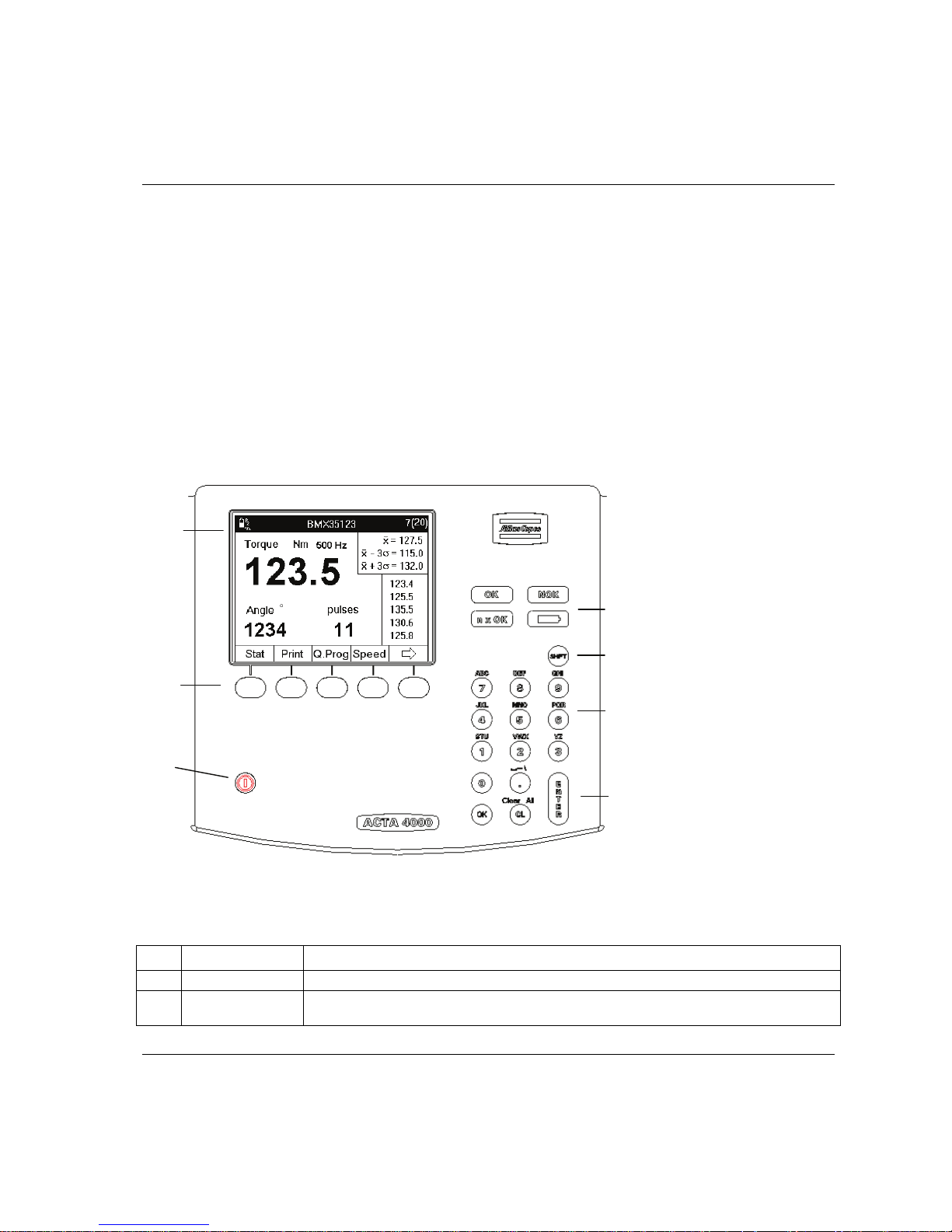
2.1 Front panel
This figure shows ACTA 4000 front panel. ACTA 3000 has the same buttons and functionality, with
minor differences in keyboard and led arrangement.
1 Display
2 Soft keys
3 On/Off button
4-7 Status (LED)
indicators
8 SHIFT
9 Numeric keypad
10-12 Function buttons
The front panel layout is the same for all versions of ACTA 4000 or ACTA 3000. Apart from the display,
it features LED indicators, soft keys and an alpha-numeric keypad.
No Name Description
1
Display
See section below
2
Display Soft
keys (Blank)
Each key corresponds to various blocks of soft key text (programming tree menus) or arrows in
the display. To configure the soft keys, see section User defined soft keys.
4-7
8
9
10-12
1
2
3

Interface ACTA 4000 User Guide
12 (136) 2008-12 9836 4171 01
3
On/Off
To start or shut down ACTA, press the button and hold down for one second
4
OK
Lights up when the result of a tightening operation falls within all the specified limits. The signal
is active for 10 seconds or until the next tightening operation is initiated.
5
NOK
Lights up when the result of a tightening operation falls outside any of the specified limits. The
signal is active for 10 seconds or until the next tightening operation is initiated.
6
n x OK
Flashes three times when the number of tightening operations corresponds to the present number
of tightening operations programmed in ACTA (Batch size)
7
Battery
Red
ACTA requires charging.
Flashing green
Charging just started, 110 / 220 V on but battery not connected or
something wrong with charging circuits.
Constant green
ACTA charging
Off
If 110 / 220 V connected, battery fully charged
If 110 / 220 V not connected, ACTA will use the battery.
8
SHIFT
Pressing the shift button activates the alphabetical signs above each numeric key. Keep pressing
the numeric key to find the desired alphabetical sign
9
Keypad
Numeric keypad. Use SHIFT to activate alphabetical signs
10
OK
OK is used to activate inputs in the programming blocks
11
Cl
The clear button is used to erase old values in the programming blocks or to delete the latest result
of the current tightening measurement.
SHIFT,Cl
Pressed in succession (but not at the same time), one of the following occurs:
All results of the current tightening torque measurements are erased
When editing data, all data is removed from an input dialog box
12
ENTER
ENTER is used to select an option and verify inputs in the programming blocks
2.1.1 Display
ACTA features a large back-lit 72 x 96 mm display with a dialog box-like interface to allow accurate
measurement readings and simple usage. ACTA 4000 has a color display, ACTA 3000 has a black and
white display.
ACTA also features a power-save function that deactivates the back-lighting on the display if it is not used
for 30 seconds. This is to save the battery and works only when ACTA is powered from the battery.
The display normally shows the
Measurement dialog box. Depending on the current task, the following
displays are available:
Measurement dialog boxes
Calibration dialog boxes
Pull-up menus
Input dialog boxes
Result windows
ACTA 4000 User Guide Interface
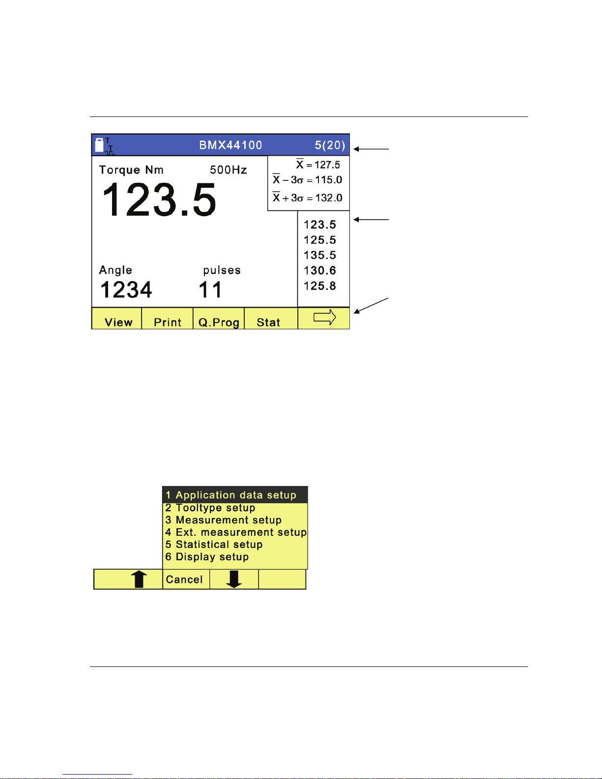
9836 4171 01 2008-12 13 (136)
Result header with battery
status, communication symbol,
tool or application name, and
number of tightenings (in
batch)
Measurement dialog box with
torque and angle results,
statistical results and last five
tightenings. This figure shows
the basic view
Menu blocks representing
programming tree functions,
arrows, or user defined options.
Controlled by the soft keys
2.1.2 Menu Blocks
The Menu blocks are located at the bottom of the display.
Each
soft key is used to select a menu block. The arrows are used to scroll through the menus.
2.1.3 Pull-up menus
When selecting a menu block with more than one function, a dialog box appears on the display.
A pull-up menu lists the options under a specific
menu block. The figure shows the pull-up menu
from the
Programming menu block.
To select an option, do one of the following:
Highlight it by scrolling up or down using
the soft keys under the arrows. Then press
ENTER.
Press the digit on the numeric keypad that
corresponds to the desired menu option.
Interface ACTA 4000 User Guide
14 (136) 2008-12 9836 4171 01
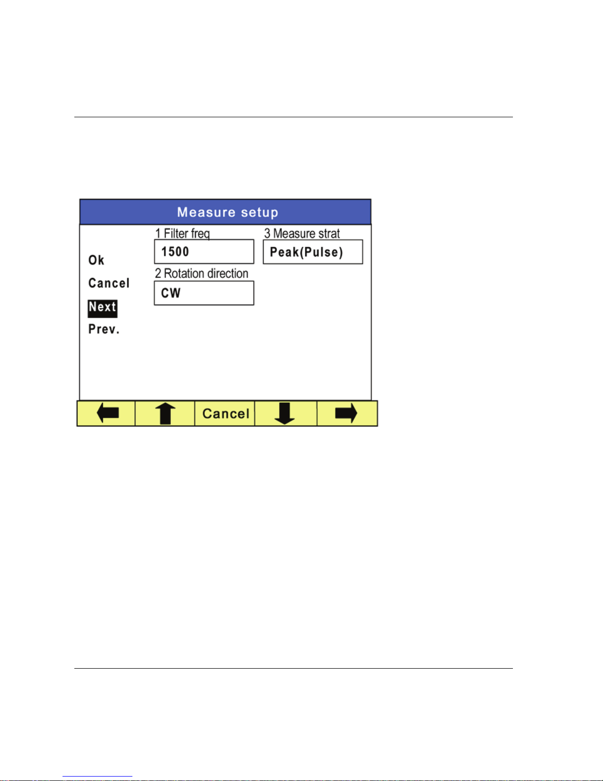
2.1.4 Input dialog boxes
An input dialog box appears if the option you have selected requires specific parameters to be set.
Opening data boxes
To access the data boxes, do
one of the following:
Highlight it by
scrolling up or down
using the soft keys
under the arrows.
Then press
ENTER.
Press the digit on the
numeric keypad that
corresponds to the
field.
The box opens.
Entering data
To enter data, do the following:
If the data field is editable, use the numeric keypad. For alpha character signs, press and release
SHIFT
prior to the numerical key representing the desired letter or symbol. Pressing and releasing associated
numeric button will cycle through applicable range of alpha characters. First lowercase and then upper
case. Press
ENTER to confirm and exit the data field. If the data field has a selection list, do one of the
following:
Use the soft keys under the arrows to highlight the desired parameter. Press
ENTER to confirm and
exit the data field.
Press the digit on the numeric keypad that corresponds to the desired parameter to confirm and exit
the data field.

ACTA 4000 User Guide Interface
9836 4171 01 2008-12 15 (136)
When all data in the dialog box is correctly filled in, do one of the following:
Highlight
OK on the display and press ENTER to confirm and exit the dialog box
Press
OK on the numeric keypad to confirm and exit the dialog box
To exit a dialog box without making any changes, do one of the following:
Highlight
Cancel in the display and press ENTER
Press the
Cancel soft key
The changes are discarded and the
Measurement (or other default) dialog box is displayed again.
Navigating in the dialog boxes
The Next and Prev. choices, when present, let you navigate to the next dialog box in the current pull-up
menu without returning to the
Measurement dialog box. When leaving the dialog box using Next or Prev.,
ACTA asks if you want the changes to be saved or not.


ACTA 4000 User Guide Getting started
9836 4171 01 2008-12 17 (136)
3 Getting started
This section describes how to get started and configure ACTA.
3.1 Out of the Box
When purchasing ACTA 4000, any version, the following is included:
Mains AC power supply cable
User guide and Product Information
Calibration certificate
USB cable
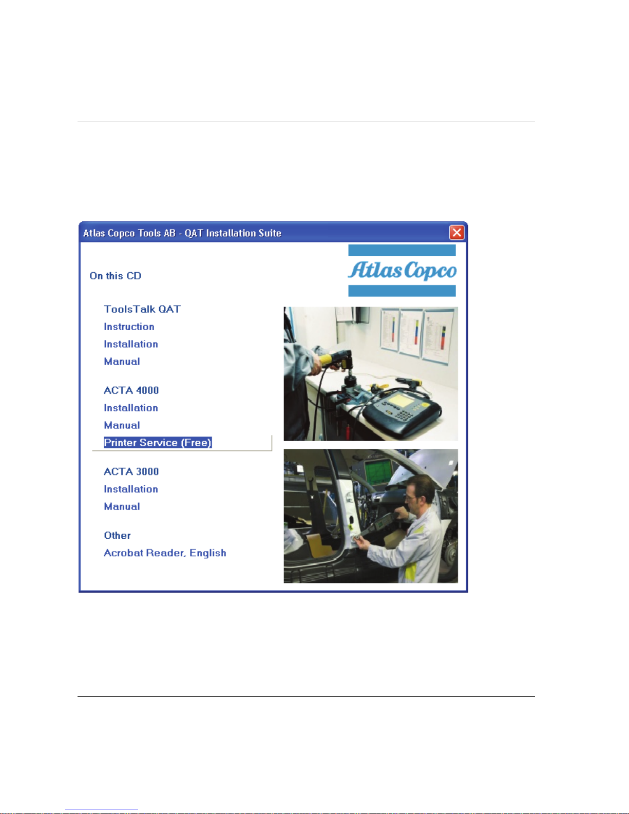
CD with ACTA software, ToolsTalk QAT software, and ACTA 4000 Printer Service
The calibration certificate must be stored in a safe place.
To access the functionality described in this user guide when using an ACTA 3000, an upgrade package is
required. Contact your Atlas Copco representative for details.
3.2 Installation
ACTA is a standalone portable product. No particular installation is necessary. Simply follow the safety
instructions and observe the following recommendations:
1. Place ACTA on a firm and flat surface or hold it securely in your hand.
2. Connect your Atlas Copco torque transducer.
3. Connect the power supply cable.
4. Start ACTA by pressing
On button until the buzzer beeps.
The first time you charge the battery, charge it for 12 hours and then use ACTA on
battery mode until the battery is completely discharged.
Getting started ACTA 4000 User Guide
18 (136) 2008-12 9836 4171 01
3.2.1 Installing software
To install the software from the CD, do the following:
1. Insert the CD into your PC.
2. Install the Printer Service and ToolsTalk QAT. Printer Service is free of charge and ToolsTalk QAT is
possible to use for 60 days without a license.

ACTA 4000 User Guide Getting started
9836 4171 01 2008-12 19 (136)
3.3 Startup
No torque must be applied to the transducer at start-up.
When you start ACTA, the following appear in the display:
1. Atlas Copco logo flashes up briefly.
2. The
Measurement dialog box appears.
3. The
Calibration dialog box flashes up briefly (if an Atlas Copco torque transducer is connected).
4. The
Measurement dialog box resumes.
ACTA initializes and performs a self-test. The
Calibration dialog box appears to indicate that ACTA is
communicating with the Atlas Copco torque transducer and performing an automatic setup. It reads the
transducer’s serial number and calibration data, which it stores in its memory.
ACTA can work with most major transducer types. If you use an Atlas Copco nonmemory transducer or a different brand, see section Technical specifications on how to set
up your transducer b
efore continuing.
3.4 Using Quick programming
This section focuses on how you can start measuring in minutes with the Quick Programming function
using Atlas Copco Torque/Angle transducers. The quick programming functions automatically make
advanced programming for you.
All versions of ACTA feature a Quick Programming function that allows you to set up a measurement
session without extensive programming knowledge. The ACTA performs the programming operations for
you. It is ideal with ACTA Basic or for quick and simple torque checks.
For information on the settings used by
Q.prog see section Default Setup, Q-prog.
The quick programming menu has three basic options:
Tool measurement programming, four different tool types
Synchronization with controller
Tool measurement according to standard ISO 5393
This section describes how to get started and perform Tool measurement without and with
synchronization. For information on tool measurement using synchronization, according to standard ISO
5393 standard, and for complete description of the menu items, selections and views, see the
corresponding section in this User Guide.
Getting started ACTA 4000 User Guide
20 (136) 2008-12 9836 4171 01
3.4.1 Measuring tools
To measure a tool using quick programming, do the following:
1. Ensure that the transducer and tool are connected. To view tool/Pset in the
Result header, open
Conf>Interface>User and set Show Pset to On.
2 Select menu block
Q.prog
3. Select the correct tool and press
ENTER.
1 Direct driven
Used when testing direct driven tools dynamically.
2 Pulse
Used when testing pulse tools dynamically.
3 Wrench
Used when checking installed torque in an already tightened joint.
4 Click wrench
Used when checking the release torque on a click wrench.
4. Select
OK to use default programming.
If
Pulse is selected, type the filter frequency in the dialog box.
If
Wrench is selected, select Peak (DD) or Static installed torque in the dialog box.
For more information about strategies, see section Measuring strategies.
For m
ore information about filter frequency, contact Atlas Copco.
5. Do the tightening operations.
The result is displayed in the
Measurement dialog box after each tightening.
6. Save and print the result.
Evaluate, and if applicable, calibrate the tool. See section Calibrating tools and equipment.
3.4.2 Measuring controlled tools with synchronization
When using Synchronize, the ACTA is configured to measure the torque in the same way as the controller.
After each tightening operation, ACTA reads the tightening values directly from the controller and from
the transducer, and stores them in the ACTA’s memory.
1. Connect ACTA and controller. To view tool/Pset in the
Result header, open Conf>Interface>User and
set
Show Pset to On.
Note! Depending on controller, a gender converter can be needed to connect to
the RS 232 connector on ACTA.

ACTA 4000 User Guide Getting started
9836 4171 01 2008-12 21 (136)
2. Select menu block Q.prog.
3. Select
Synchronize and press ENTER.
4. Select controller.
1 None
2 Other controller
Select tool type and insert input target torque.
For pulse tools, also insert filter frequency
For wrenches, select measurement strategy
Static installed torque
or
Peak (DD).
3 Focus2000/PF2000
4 DS/DL
Select
RS232 as type of communication.
For Focus2000/PF2000 with RS232 Communication, enter unit ID
when requested.
5 PF3000/PF4000
6 PowerMACS
Select
RS232 as type of communication.
5. Do the tightening operations.
The results from the controller and the transducer are displayed in the
Measurement dialog box after
each tightening. The controller display shows only the controller result.
Note: The DS/DL controller does not send a value as the torque tuning is made against the controller
target value.
6. Save and print the result.
Evaluate, and if applicable, calibrate the tool. See section Calibrating tools and equipment.
References
For details on Statistics and calculation of the parameters, see section Guide to statistics.
For instructions on how to calibrate, see section Calibrating tools and equipment
For inform
ation about printouts, see section Printouts from ACTA
For explanation of all m
enu items, see section Programming ACTA.

Getting started ACTA 4000 User Guide
22 (136) 2008-12 9836 4171 01
3.5 Connecting ToolsTalk QAT
To connect a computer with ToolsTalk QAT to ACTA, do the following:
1. Connect ACTA and the computer with RS 232 cable or USB cable, or connect ACTA to the
network with an Ethernet cable.
2 Open
Conf>Interface>Communication>TTQAT and go to 1 TTQAT media.
3. Select the correct connection type and press
ENTER.
1 RS232
2 USB
3 Ethernet
Fill in the connection data. DHCP is default.
To continue connecting to and working with ToolsTalk QAT, see the ToolsTalk QAT user guide.

ACTA 4000 User Guide Programming ACTA
9836 4171 01 2008-12 23 (136)
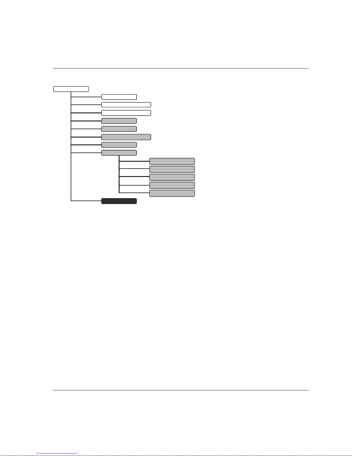
4 Programming ACTA
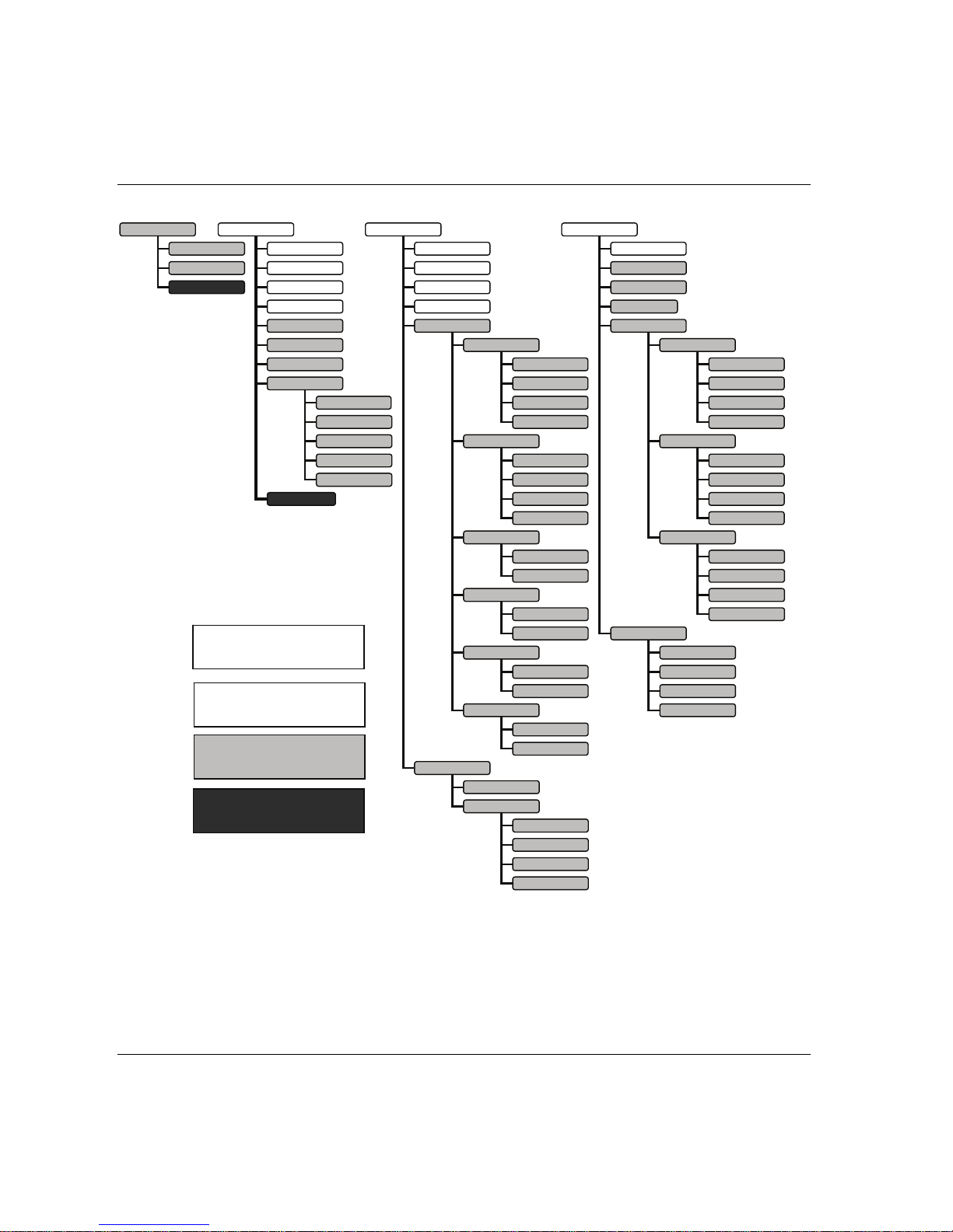
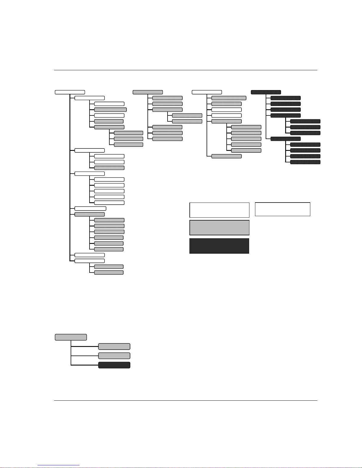
This section shows the programming tree for ACTA Basic, Quality Control and Advanced Analysis,
displaying the full functionality of each version.
The section explains how to use the different functions and parameters of the programming tree to
program your ACTA. If your ACTA version does not feature a specific menu block (depending on its
functionality), simply skip that menu block and continue with the next one.
For information on how to navigate through the programming tree, how to find and select specific
functions (parameters) and how to input values, see section Interface.
The subchapters present the menus in the same order as in the programming tree.
The shading makes it easy to distinguish between the variants.
When the programming tree differs between ACTA 3000 and ACTA
4000, this is indicated with a footnote.
Basic, Quality Control &
Advanced Analysis
Quality Control &
Advanced Analysis only
Advanced Analysis only
Programming ACTA ACTA 4000 User Guide
24 (136) 2008-12 9836 4171 01
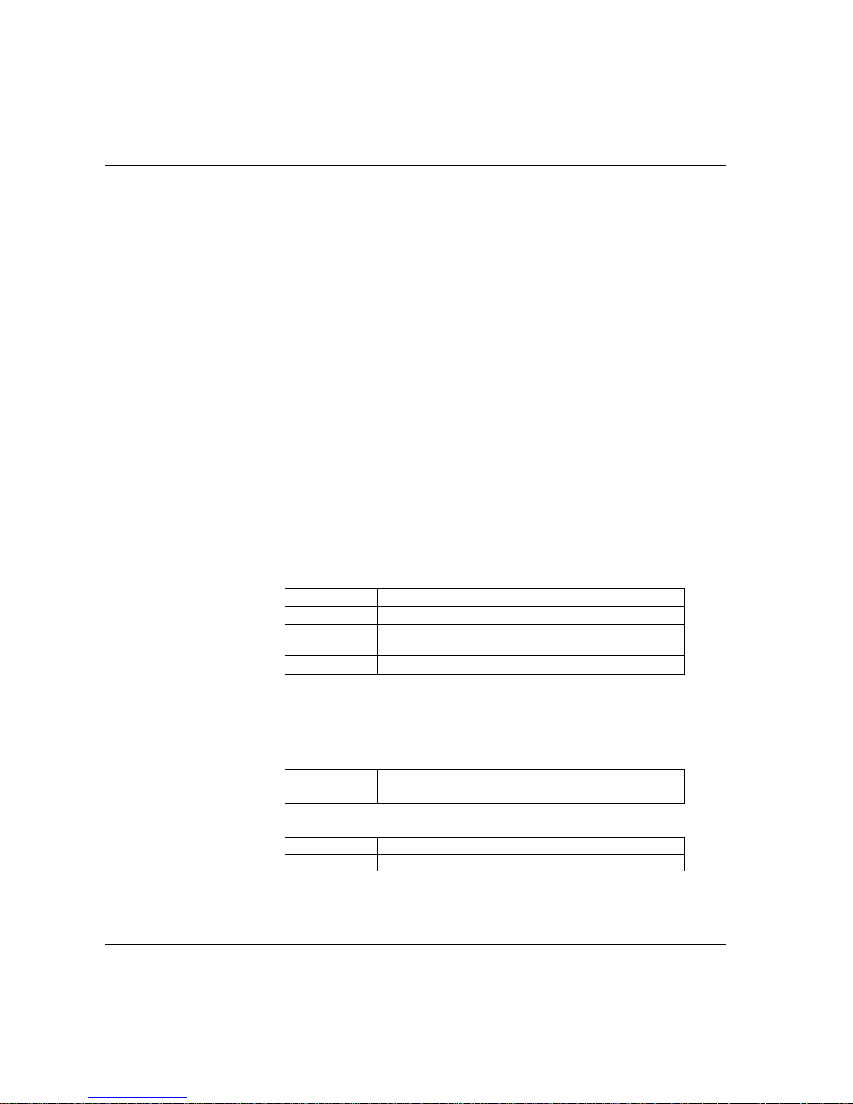
View Print Q.Prog Stat
Continuous
Tool rundowns
Transducer info
Tool setup
Tool statistics
Tool calibration
ISO 5393
Database
All tools rundown
All tools setup
All tools statistics
All tools calibration
Database summary
Direct driven
Pulse
Wrench
Click wrench
Synchronize
ISO 5393
None
Other controller
Focus2000/PF2000
DS/DL
PF3000/PF4000
PowerMACS
Manual input
RS232
Manual input
RS232
Manual input
RS232
Manual input
RS232
All tightening
Statistics torque
Statistics angle
Statistics pulses
History
Manual input
Torque
Angle
Table
X graph
R graph
σ graph
Table
X graph
R graph
σ graph
Tightening
Tool Comment
Controller
Sequence no
Basic
Custom
Trace
Standard
Custom
Pulses
Table
X graph
R graph
σ graph
Direct driven
Pulse
Wrench
Click wrench
Basic, Quality Control &
Advanced Analysis
Quality Control &
Advanced Analysis only
Advanced Analysis only
Direct driven
Pulse
Wrench
Click wrench
Direct driven
Pulse
Wrench
Click wrench
1) ACTA 3000
2) ACTA 4000
Trace
ACTA 4000 User Guide Programming ACTA
9836 4171 01 2008-12 25 (136)
4.1 View
The View function allows you to switch between the Measurement dialog boxes available in your version
of ACTA. There are up to three different measurement dialog boxes depending on ACTA version.
View
1 Basic
2 Custom
3 Trace
Conf Datab Pro
g
A.lyse
Interface
Calibration
Diagnostics
Communication
Product information
Options
User
User defined soft keys
Tightenin
g
Communication 2)
ACTA
Deadweight
Tool
Transduce
r
Batter
y
Trac
kSpeed
Shunt calibration
Controlle
r
ToolsTalk QAT
Barcode
New tool
Select tool
Delete tool
Clear all measurements
Backup tool
Information
Selected tool
All tools
Application data setu
p
Tool type setu
p
Measure setu
p
Ext measure setu
p
Statistical setu
p
Display setu
p
Group and batch
Torque
Angle
Pulses
Non torque stat
Zoom in
Zoom out
Adjust position
Save trace
Paramete
r
Low
Medium
High
Torque (angle
)
Torque (time
)
Angle (time
)
Torque, angle (time
)
Basic, Quality Control &
Advanced Analysis
Quality Control &
Advanced Analysis only
Advanced Analysis only
Transducer memory
Options
Options
Ethernet
TT QAT
Barcode
1) ACTA 3000
2) ACTA 4000
Port 1
)
Start tightenin
g
Start Batch
Reverse

Programming ACTA ACTA 4000 User Guide
26 (136) 2008-12 9836 4171 01
1 Basic
The Basic dialog box is the standard view in ACTA, available in all
versions.
2 Custom
The Custom measurement dialog box is available in ACTA Quality Control
and Advanced Analysis.
3 Trace
The Trace measurement dialog box is available in ACTA Advanced
Analysis only.
4.2 Print menu
Since the printing feature for ACTA 3000 and ACTA 4000 is different, follow the instructions applicable
to your unit. For example of printouts, see section Printouts from ACTA.
ACTA 4000
To be able to print reports from ACTA 4000, ACTA 4000 Printer Service software must be installed on a
PC and ACTA connected to it through the serial or the USB port. The report selected in ACTA is printed
on the printer that is set up from the PC.
ACTA 3000
ACTA 3000 must be connected to a printer directly through the printer port. See the ACTA 3000 user
guide.
ACTA 4000 User Guide Programming ACTA
9836 4171 01 2008-12 27 (136)
Print menu, ACTA 3000 and ACTA 4000
1 Continuous
Starts a printout of the tightening result after each tightening
operation. The printout is in the form of a list. To stop continuous
printing, press the
Print soft key again. The Continuous list member
is now replaced by
Abort continuous. Select Abort continuous and
the printout ends (a footer and form feed is printed).
2 Tool rundowns
Prints all tightening operations for selected tools.
3 Transducer info
Prints transducer info for connected transducers.
4 Tool setup
Prints the setup for selected tools.
5 Tool statistics
Prints statistics for selected tools.
6 Tool calibration
Prints a calibration report for selected tools. A tool calibration should
have been performed prior to the printout.
7 ISO 5393
Prints ISO 5393 calibration report. An ISO 5393 calibration must
have been performed prior to the printout.
Print
1 Continuous
2 Tool rundowns
3 Transducer info
4 Tool setup
5 Tool statistics
6 Tool calibration
7 ISO 5393
8 Database
1 All tools rundown
2 All tools setup
3 All tools statistics
4 All tools calibration
5 Database summary
9 Trace

Programming ACTA ACTA 4000 User Guide
28 (136) 2008-12 9836 4171 01
8 Database
Select submenu:
1 All tools rundowns
Prints all tightening operations for all tools.
2 All tools setup
Prints the setup for all tools.
3 All tools statistics
Prints statistics for all tools.
4 All tools calibration
Prints a calibration report for all tools. A tool
calibration should have been performed for all
tools prior to the printout.
5 Database summary
Prints a summary of all tools.
9 Trace
Prints a trace of the last tightening operation. For ACTA 4000,
ToolsTalk QAT must be used for printing traces.
To terminate a printout in progress, press menu block
Abort.
See section Port for print settings, and section Printouts from ACTA for examples of the printout reports.

ACTA 4000 User Guide Programming ACTA
9836 4171 01 2008-12 29 (136)
4.3 Quick Programming (Q.Prog.)
For programming instructions, see section Using Quick programming.
1) ACTA 3000 only
Programming ACTA ACTA 4000 User Guide
30 (136) 2008-12 9836 4171 01
4.3.1 Quick programming tools
The following tools are available from the menu. See section Q-prog for information about the tool
parameters.
1 Direct Driven
Selected if a direct driven tool is tested.
2 Pulse
Selected if a pulse tool is tested.
3 Wrench
Selected if a wrench is tested.
4 Click Wrench
Selected if a click wrench is tested.
4.3.2 Synchronize
Synchronization is a method where ACTA is programmed to measure the torque in the same way as the
controller. The following controllers are available.
For information on the synchronization procedure, see section Measuring controlled tools with
sy
nchronization.
1 None
Selected when no controller is connected and the value is entered
manually.
1 Direct driven
Used when testing direct driven tools dynamically.
2 Pulse
Used when testing pulse driven tools dynamically.
3 Wrench
Used when checking installed torque in an already tightened
joint.
4 Click wrench
Used when checking the release torque on a click wrench.
2 Other controller
Selected when a non-Atlas Copco controller is used.
For tool type, see above.
3 Focus2000/PF2000
Type of controller.
1 Manual input
Used if no connection is possible.
2 RS232
Normally used for direct communication with controller
4 DS/DL
Type of controller.
1 Manual input
Used if no connection is possible.
2 RS232
Normally used for direct communication with controller
 Loading...