

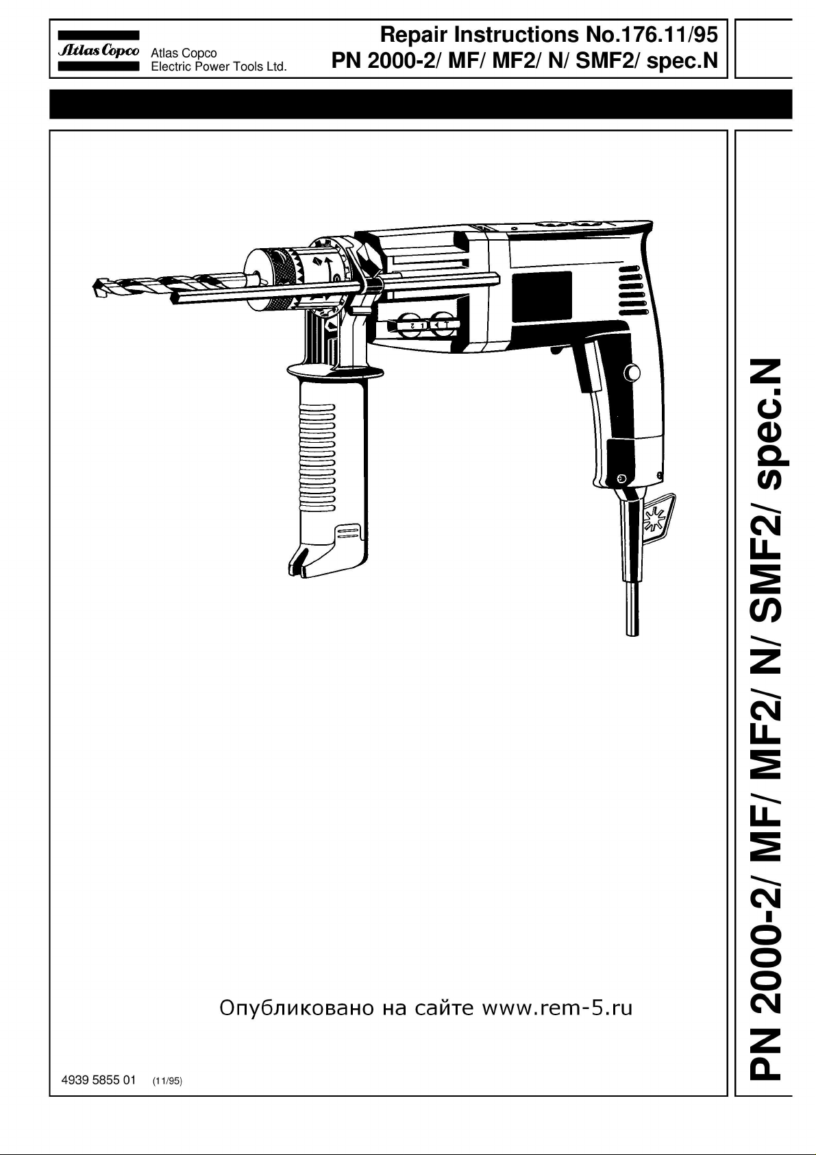
Atlas Copco 2000-2/MF, 2000-2/MF2, 2000-2/N, 2000-2/SMF2 Repair Instructions
PAGE
Repair Instructions No.176.11/95
PN 2000-2/ MF/ MF2/ N/ SMF2/ spec.N
Special Tools
Required
■
Mandril (diameter 9.5 mm), approx. 100 mm long.
■
Assembly support in which the tool can be fixed vertically.
Important!
■
Before beginning the maintenance work, perform an initial check with a high voltage test according
to VDE (see chapter Electrical and Mechanical Test Instructions).
■
Before all repair work, pull the power plug from the socket!
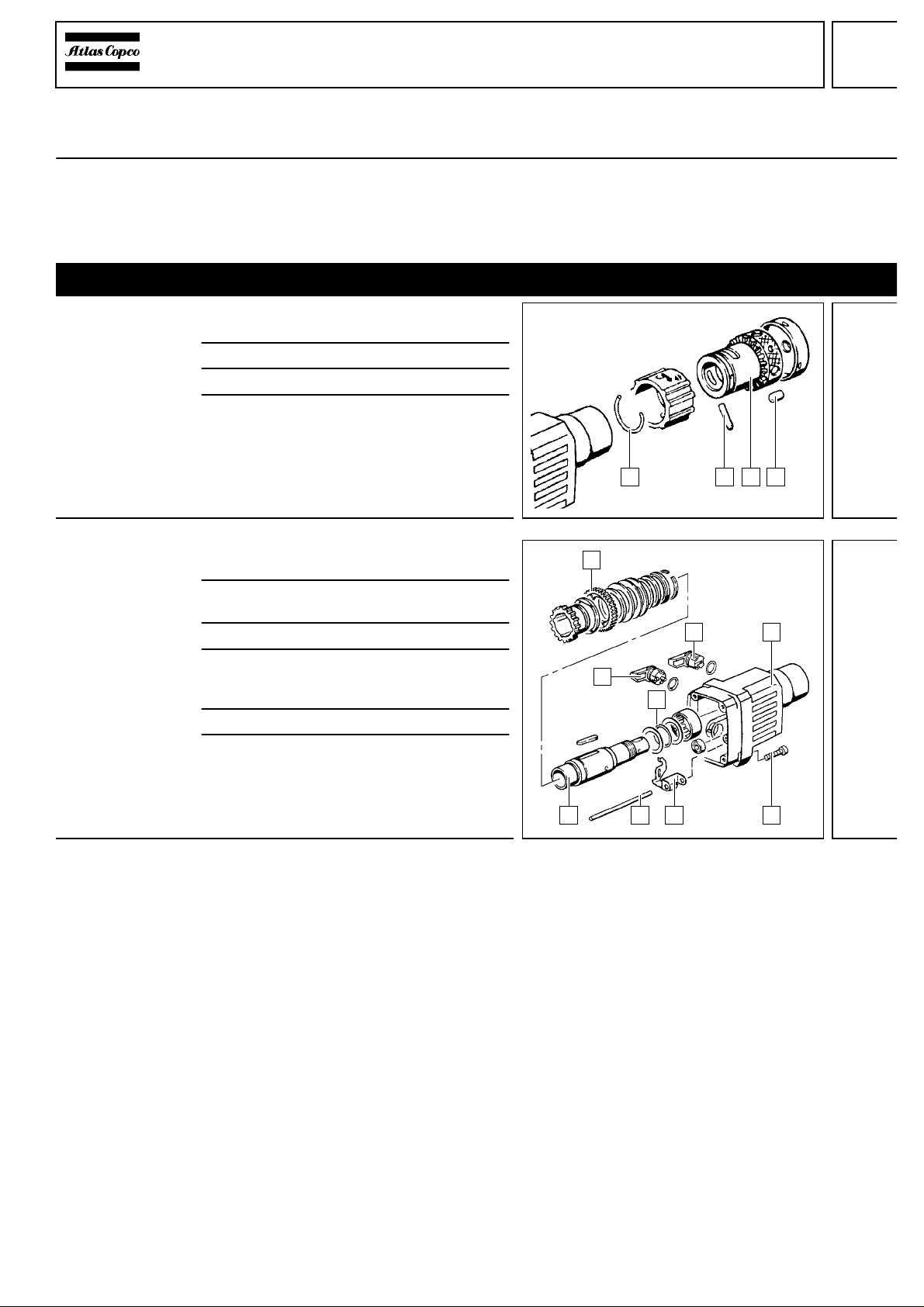
Disassembly
Dismantling the
chuck
1
Lever off the spring washer (4) with aid of
a screwdriver.
134
1
89
1
5
3
67
4
2
2 Remove the pin (3) and the roller (1).
3 Pull off the multi-function chuck (2).
4 Only applicable for PN 2000 spec. N:
Remove the hammer chuck.
2
1
Dismantling the
gear box
1 Insert the machine into the assembly
support and remove the four screws (6).
2 Lever off the switch levers (2) and (4) with
aid of a screwdriver.
3 Remove the gear box (5).
4 Remove the pin (8), the gear switch
lever (7), and the O-ring (3) together with the
discs.
5 Remove the gear wheel (1).
6 Remove the spindle sleeve (9).
2

PAGE
Repair Instructions No.176.11/95
PN 2000-2/ MF/ MF2/ N/ SMF2/ spec.N
Dismantling the
reduction gear
1
Remove the axial needle bearing (4).
3 4
567
8
2
3
6
1
2 5
4
4
2 Take out the complete reduction gear,
then remove the reduction gear shaft (8).
3 Remove the needle bearing (2) and the
sealing ring (1).
4 Remove the sleeve (7), the pin (6), and
the bearing (3).
5 Remove the gasket (5).
2
1
Dismantling the
cylinder
1 Remove he cylinder (3) together with the
percussion body (4). Pull the percussion
body (4) from the cylinder (3).
2 Press the snap die (2) from the drill
spindle (5) with aid of a mandril. The
spring ring, the washer, and the rubber
ring are being destroyed.
3 Remove the sealing ring (6).
4 Remove the needle bearing (1).
3
 Loading...