

Page 1
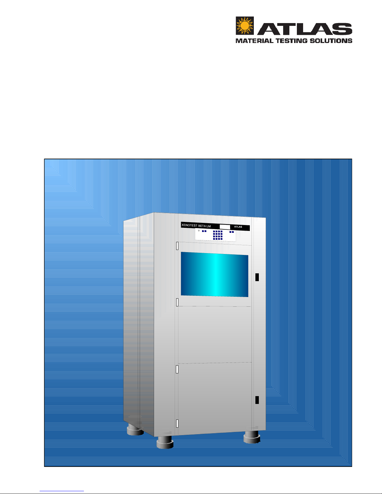
XENOTEST BETA LM
Operating manual
Page 2

Operating manual XENOTEST BETA LM ATLAS
Page 2
Page 3

ATLAS Operating mannual XENOTEST BETA LM
Page 3
XENOTEST BETA LM
Operating manual
Page 4

Operating manual XENOTEST BETA LM ATLAS
Page 4
Contents Page
1. Introduction ............................................................................................................................... 7
1.1 Warranty hints ................................................................................................................... 7
1.2 Safety hints ....................................................................................................................... 8
2. XENOTEST BETA features ..................................................................................................... 10
3. Setting up the unit .................................................................................................................. 11
3.1 Scope of delivery XENOTEST BETA LM ........................................................................ 11
3.2 Installation requirements ................................................................................................. 11
3.2.1 Laboratory ....................................................................................................................... 11
3.2.2 Room ventilation ............................................................................................................. 11
3.2.3 Electrical supply .............................................................................................................. 11
3.2.4 Space requirements ........................................................................................................ 12
4. Description of the unit ............................................................................................................ 14
4.1 Front panel of the unit ..................................................................................................... 14
4.1.1 Program control............................................................................................................... 15
4.1.2 Test chamber .................................................................................................................. 16
4.1.3 Water tank....................................................................................................................... 16
4.2 Right panel of the unit ..................................................................................................... 18
4.3 Upper side of the unit ...................................................................................................... 18
4.4 Left panel of the unit .......................................................................................................20
4.5 Rear panel....................................................................................................................... 20
4.6 Air circuits ....................................................................................................................... 22
5. Option and accessories of XENOTEST BETA ...................................................................... 23
5.1 Options............................................................................................................................ 23
5.1.1 Rain-, humidity function and sample cooling ................................................................... 23
5.1.2 Printer ............................................................................................................................. 24
5.1.3 Mains transformers ........................................................................................................27
5.1.4 Interface .......................................................................................................................... 27
5.2 Accessories..................................................................................................................... 28
5.2.1 Filter system ................................................................................................................... 28
5.2.2 Sample holders set standard .......................................................................................... 30
5.2.3 Special sample holder ..................................................................................................... 30
5.2.4 Exposure cards ............................................................................................................... 30
5.2.5 Cover plates .................................................................................................................... 30
5.2.6 XENOSENSIV sensor ..................................................................................................... 31
5.2.7 XENOSENSIV sensor support sheet .............................................................................. 31
5.2.8 Calibration adapter and end plug .................................................................................... 31
6. Start up .................................................................................................................................... 32
6.1 Fitting the filter to the lantern .......................................................................................... 32
6.2 Insertion of the XENOTEST light exposure system ........................................................ 32
6.2.1 Insertion of the lamps and the filter lantern..................................................................... 34
6.2.2 Exchange of lamps ......................................................................................................... 34
6.3 Water supply ................................................................................................................... 34
6.4 Insert the XENOSENSIV sensor ..................................................................................... 34
6.5 Calibration of the XENOSENSIV sensor ........................................................................ 36
6.6 Fitting of the end plug ..................................................................................................... 36
6.7 Sample back cooling ....................................................................................................... 36
Page 5

ATLAS Operating mannual XENOTEST BETA LM
Page 5
Contents Page
7. Function................................................................................................................................... 37
7.1 Measuring and control sensor system ............................................................................ 37
7.1.1 Control of the irradiance .................................................................................................. 37
7.1.2 Control of the black standard temperature ...................................................................... 37
7.1.3 Control of the fan speed .................................................................................................. 37
7.1.4 Control of the test chamber temperature ........................................................................ 38
7.1.5 Control of the chamber humidity ..................................................................................... 38
7.2 Rain................................................................................................................................. 38
7.3 Sample back cooling ....................................................................................................... 38
7.4 Program control system ................................................................................................. 39
7.5 Temperature diagrams .................................................................................................... 39
8. Program example on XENOTEST BETA ................................................................................ 40
8.1 Task of the program ........................................................................................................ 40
8.2 Solving the program task ................................................................................................ 40
8.3 Program start .................................................................................................................. 44
8.4 Reading during program run ........................................................................................... 45
8.5 Data print out .................................................................................................................. 46
8.6 Change speed of blower during program operation......................................................... 47
8.7 Stop a running program .................................................................................................. 47
8.8 Trouble shooting .............................................................................................................. 48
9. Setting up tests ....................................................................................................................... 51
9.1 Equip sample holders...................................................................................................... 51
9.2 Select unit parameters .................................................................................................... 51
9.3 Test duration.................................................................................................................... 51
10. Care and cleaning ................................................................................................................... 52
10.1 Cleaning of quartz- and glass components ..................................................................... 52
10.2 Cleaning the test chamber .............................................................................................. 52
10.3 Cleaning the water tank .................................................................................................. 52
10.4 Changing air filter ............................................................................................................ 52
11. Maintenance ............................................................................................................................ 53
12. List of options and accessories ............................................................................................ 53
12.1 Options............................................................................................................................ 53
12.2 Accessories..................................................................................................................... 54
13. Technical data ......................................................................................................................... 55
Page 6

Operating manual XENOTEST BETA LM ATLAS
Page 6
Fig. 1 Space requirements ........................................................................................................12
Fig. 2 Unit dimensions ............................................................................................................... 13
Fig. 3 Front side of equipment .................................................................................................. 14
Fig. 4 Program control ............................................................................................................... 15
Fig. 5 Water tank ....................................................................................................................... 16
Fig. 6 Test chamber .................................................................................................................. 17
Fig. 7 Main switch ..................................................................................................................... 18
Fig. 8 Right side of the unit ....................................................................................................... 19
Fig. 9 Left side of the unit.......................................................................................................... 21
Fig. 10 Ventilation scheme .......................................................................................................... 22
Fig. 11 Water circuits .................................................................................................................. 23
Fig. 12 Printer ............................................................................................................................. 24
Fig. 13 Printer parameter ............................................................................................................ 25
Fig. 14 Printer scheme................................................................................................................ 26
Fig. 15 Change of the paper roll.................................................................................................. 27
Fig. 16 Mains transformers ......................................................................................................... 27
Fig. 17 Pin designation RS232....................................................................................................27
Fig. 18 XENOCHROME filter system and path of radiation ........................................................ 28
Fig. 19 Spectral Distribution XENOCHROME 300 and CIE 85 ................................................... 29
Fig. 20 Spectral Distribution XENOCHROME 270 and 320 ........................................................ 29
Fig. 21 Sample holder set standard ............................................................................................ 30
Fig. 22 Cover plate ...................................................................................................................... 30
Fig. 23 XENOSENSIV sensor ..................................................................................................... 31
Fig. 24 XENOSENSIV sensor support sheet .............................................................................. 31
Fig. 25 Insertion of the XENOSENSIV exposure system ............................................................ 33
Fig. 26 Insertion of the XENOSENSIV sensor ............................................................................ 35
Fig. 27 Calibration adapter .......................................................................................................... 36
Fig. 28 End plug .......................................................................................................................... 36
Fig. 29 Sensor for test chamber temperature and rel. humidity .................................................. 37
Fig. 30 Humidity diagram ............................................................................................................ 38
Fig. 31 Temperature fields........................................................................................................... 39
List of graphics Page
Page 7
ATLAS Operating manual XENOTEST BETA LM
Page 7
1. Introduction
Dear BETA User!
The new XENOTEST BETA LM presents you with a state-of-the-art light exposure and weathering
equipment for obtaining vital information about the long term behaviour of your products when exposed
to the influences of weather, and solar radiation in particular, using the time acceleration effect. The
optimum conditions for an accelerated laboratory test are created by simulating the natural influencing
factors and simultaneously intensifying important parameters at sample level.
Important hints
The XENOTEST unit is planned for research, development and test laboratories. The safety of the persons, the environment and the materials used, depend essentially on the persons operating the equipment. Use the manual to instruct the operating personnel in the operation, function and care of the
XENOTEST BETA. Inform the operating staff about accident prevention regulations regularly.
Please read this operating manual extremely carefully before starting your system. This will enable you to
make full use of its features and will prevent possible damage.
1.1 Warranty hints
Handling and usage contrary to the regulations described in the operating manual lead to loss of warranty claim. The unit has been designed and manufactured with skill and care and was quality tested before
despatch. Inspections, maintenance and repair work may be carried out only by ATLAS or an authorized
customer service engineer, otherwise the safety of the system is not guaranteed.
Sign explanation:
ATTENTION!
ATTENTION! is used when the non-compliance with instructions may cause damage to the system.
DANGER!
DANGER! is used when the non-compliance with instructions may cause danger to the user.
DANGEROUS VOLTAGE!
DANGEROUS VOLTAGE! is used when the non-compliance with instructions because of dangerous
voltage may cause danger to the user.
Page 8

Operating manual XENOTEST BETA LM ATLAS
Page 8
1.2 Safety hints
• Operating the system presupposes knowledge of this manual. The operating manual should be
kept close to the unit.
• For work at and with the unit the user needs instructions in his mother language based on the
operating manual (FRG: UVV VBG1 § 7 (2)).
• The XENOTEST BETA units shall only be used for the exposure and weathering of materials in
the intended areas of application .
• For the functioning of the water circuits and the humidity system the unit has to be leveled by its
height adjustable feet.
• Before starting the unit ensure that the necessary requirements for a failurefree operation of the
unit are given. Observe the installation requirements in chapter 2.2 of this manual as well as
valid national laws, regulations and guiding principles.
• Inflammable or explosive materials at temperatures below 150 °C must not be inserted into the
unit.
• Do not insert materials which despite their application as directed release toxical substances.
• Disconnect the system from the mains before carrying out any maintenance work, e.g. exchange
of lamps, cleaning, emptying the water tank (remove the safety contact plug).
• The lamp is switched off when the test chamber door is opened. The lamp must be re-ignited to
continue testing once the door has been closed again.
• The lamp is switched off when the casing lid on the upper side of the unit is opened. The lamp
must be re-ignited to continue testing once the casing lid has been closed again.
• Within the stipulated proof intervals, or at least once a year, the door safety switch and the
safety device of the upper casing lid have to be proved for their safety function.
• Within the stipulated proof intervals, or at least once a year, the temperature cut-offs of the
humidifier, lamp supply, heating system and the lamp exhaust air have to be proved for their
safety function.
• Within the stipulated proof intervals, however at least once a year, the water level indicator
switch of the water tank and the humidityfier have to be proved for their safety function.
• Within the stipulated proof intervals, or at least once a year, the carousel switch of the water
tank and the humidifier have to be proved for their safety function.
• Sample holders must be inserted carefully into the carousel. Incorrectly fitted sample holders
can work out of their mountings and cause damage.
Unit set-up
Unit description
List of options
and accessories
Start-up
Care and cleaningTest set-up
Program example on
XENOTEST BETA
XENOTEST BETA
Features
Safety hints
Function
Options and accessory
of the XENOTEST BETA
Maintenance
Page 9

ATLAS Operating manual XENOTEST BETA LM
Page 9
• The cable of the lamp contact plugs are provided with numbers. It´s absolutely necessary to
ensure that the lamp contact plugs are connected to the corresponding lamps (fig. 25).
• Under extreme conditions, especially at high temperature exposures lamps, specimens,
specimen holders and sensors heat up considerably during the weathering tests. Protective
gloves must therefore be worn when removing them to prevent injury to your hands. This applies
in particular to high temperature tests.
• Because of exhaust air temperatures up to 120 °C max. the hoses of lamp and test chamber air
outlets must be of flexible and heat resistant material.
• The maximum length of the exhaust air hoses of lamp and test chamber including two 90° bendings is limited to 3 meters. With longer exhaust air hoses or more than two 90° bendings an
external blower is required.
• Overheating may occur if air inlets or outlets are obstructed. Please ensure that the necessary
space is available (fig. 1).
• The unit has to be switched off when carrying out any maintenance work. Turn the main switch to
position "0" and pull mains plug. Secure against reconnection to the mains.
• Inspections, maintenance and repair work may only be carried out by ATLAS or an authorised
customer service engineer, otherwise the safety and operation of the system is not guaranteed.
• Your XENOTEST BETA is developed by experienced designers and manufactured in
accordance with legislation on technical equipment and VDE Standard 0113/ 06.93.
The unit complies with the safety standards of:
• DIN VDE 0411 part 1 / 03.94
Measuring, Regulating, Controlling
Safety requirements for electric motor-operated measuring, regulating, controlling and
laboratory units.
• DIN VDE 0711 part 1 / 09.91
Lamps
• DIN VDE 0875 part 14 / 09.91
Limits and methods of measurement of radio disturbance characteristics of electric motoroperated and thermal appliances for household and similar purposes, electric tools and similar
electric apparatus. (EN 55 014)
Unit set-up
Unit description
List of options
and accessories
Start-up
Care and cleaningTest set-up
Program example on
XENOTEST BETA
XENOTEST BETA
Features
Safety hints
Function
Options and accessory
of the XENOTEST BETA
Maintenance
• DIN VDE 0871 part 11/09.87
Limits of radio disturbance and measuring methods for industrial, scientific and medical highfrequency apparatus (EN 55 011).
Page 10
Operating manual XENOTEST BETA LM ATLAS
Page 10
Unit set-up
Unit description
List of options
and accessories
Start-up
Care and cleaning
Test set-up
Program example on
XENOTEST BETA
XENOTEST BETA
Features
Safety hints
Function
2. XENOTEST BETA Features
The following table shows the physical data of the XENOTEST BETA .
Options and accessory
of the XENOTEST BETA
Maintenance
Pos. Feature Data
1 Control system / Microprocessor • 10 prestructured programs
• 12 cycles per program
2 Integrated sensors:
• XENOSENSIV for irradiance and
black standard temperature
• Sensor for test chamber temperature
and rel. humidity
Wavelength range 300 - 400 nm
Surface temperature --> 130 °C
Ambient temperature --> 80 °C
10 - 95 %
3 Irradiation:
Filter
• XENOCHROME 270
• XENOCHROME 300
• XENOCHROME 320
Irradiance:
Wavelength range 300-400 nm
60 - 165 W/m²
45 - 120 W/m²
35 - 100 W/m²
4 Weathering surface • Sample holder dimensions 320 mm x 80 mm
• 16 sample holders
• Total surface approx.. 4000 cm²
5 Xenon lamps NXE 2200 3 lamps / life time min. 1500 hours (within irradiance
range)
6 Nominal rating of lamp 2200 VA / lamp with readjusting
7 Power consumption max. 12 kVA
8 Dimensions:
Width x Depth x Height 900 mm x 1200 mm x 1800 mm
9 Weight approx. 400 kg
10 Options:
External sensors
Printer
Interface
• XenoCal UV
• XenoCal Global
• Black standard temperature sensor
• White standard temperature sensor
Thermoprinter
RS232 / RS 485
11 Electrical connection 400 V ± 10 %, 50-60 Hz, (3/N/PE),
CEE (32A, 5pol.,6h)
12 Noise level < 75 db(A)
Page 11
ATLAS Operating manual XENOTEST BETA
Page 11
3. Unit set-up
Unit set-up
Unit description
List of options
and accessories
Start-up
Care and cleaningTest set-up
Program example on
XENOTEST BETA
XENOTEST BETA
Features
Safety hints
Function Maintenance
Options and accessory
of the XENOTEST BETA
To ensure the functioning of the water circuit and
the humidification system, the apparatus
must be aligned by means of its height
adjustable feet.
3.1 Scope of delivery
XENOTEST BETA LM
The unit is supplied in a suitable shipping case.
Sensitive components such as:
1. Xenon lamps,
2. optical filter system,
3. sample holders and cover masks,
4. XENOSENSIV sensor,
5. outer cylinder,
are packed separately.
The scope of delivery includes (other fittings are
available when wished):
1. Control system with display and operating
keyboard,
2. 3 Xenon lamps (type NXE 2200),
3. Sensor to measure test chamber
temperature and rel. humidity,
4. XENOSENSIV sensor to measure the
irradiance in the UV range from 300400 nm and the black standard temperature,
5. End plug for operation without
XENOSENSIV sensor,
6. Support sheet to fix the XENOSENSIV
sensor on to the sample holder,
7. XENOCHROME filter system consisting of
filter lantern with 11 special filters,
8. Outer cylinder made of quartz glass and
special UV glass (suprax),
9. 16 standard sample holders,
10. 16 masking sheets to fix unstable samples
on the sample holder,
11. Water tank,
12. Thermo printer
13. Interface RS232 / RS485
Technical documentation:
Operating manual, circuit diagrams, spare
parts list.
14.
3.2 Space requirements
3.2.1 Laboratory
To avoid contamination and to ensure reproducibi-
lity of the climatic conditions, we recommend to install the equipment in an airconditioned and air-filtered (filter type EU4)
laboratory at 18°C - 25°C and a relative
air humidity of 50%.
3.2.2 Room ventilation
The XENOTEST BETA needs 200 m³/h air to cool
down the xenon lamps and 200 m³/h air to
cool down the test chamber. An amount
of 400 m3/h fresh air has to be supplied to
the laboratory via an air filter (filter type
EU4).
3.2.3 Electrical connection
The unit is designed for a mains supply of
400V ± 10%. Connection is ensured by
safety contact plug (3,N,PE), CEE (32,
5pol., 6h).
• For the electrical supply observe UVV
VGB 4.
• Mains conditions have to agree with the
data on the identity label .
• Observe VDE and technical connection
regulations of the energy supply companies.
Page 12
Operating manual XENOTEST BETA LM ATLAS
Page 12
Unit set-up
Unit description
List of options
and accessories
MaintenanceCare and cleaningTest set-up
Program example on
XENOTEST BETA
XENOTEST BETA
Features
Safety hints
Function
Options and accessory
of the XENOTEST BETA
Start-up
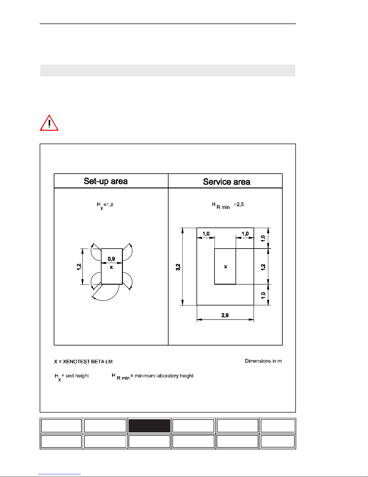
Figure 1: Space requirement
3.2.4 Space requirement (fig. 1)
Dimensions of XENOTEST BETA
(Width x depth x height):
900m x 1200mm x 1800mm.
For adequate cooling of the xenon lamps,
take care that the air inlets and outlets at
the top and back side of the equipment
are not obstructed. Allow for the necessary space
for operation, maintenance and repair of the
equipment.
Page 13
ATLAS Operating manual XENOTEST BETA
Page 13
Unit set-up
Unit description
List of options
and accessories
Start-up
Care and cleaningTest set-up
Program example on
XENOTEST BETA
XENOTEST BETA
Features
Safety hints
Function
Options and accessory
of the XENOTEST BETA
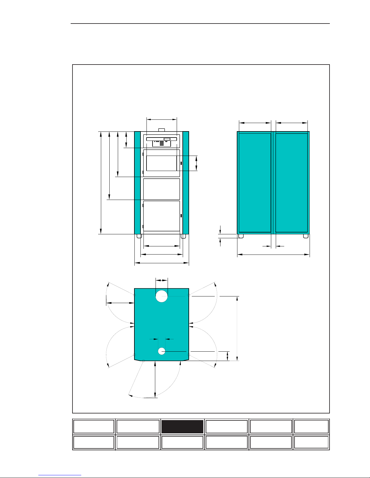
530
XENOTEST BETA LM
HERAEUS
Instruments
ø100
80
460
1180
585
610
860
ø200
470
2
2
0
6
8
5
1
1
1
0
1
6
2
0
1
0
0
3
4
5
1
0
6
0
320
460
5
9
0
Figure 2: Unit dimensions (in mm)
Maintenance
Page 14
Operating manual XENOTEST BETA LM ATLAS
Page 14
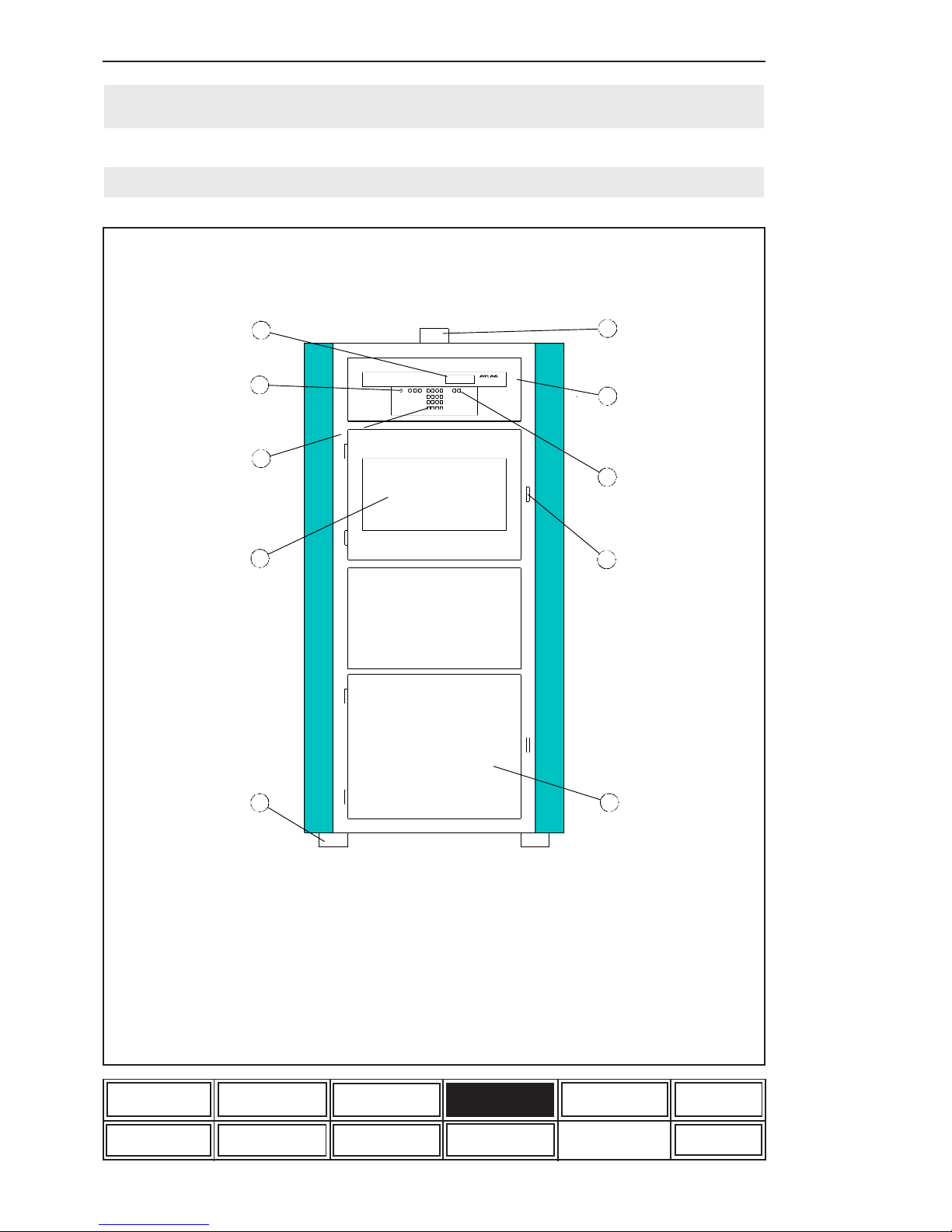
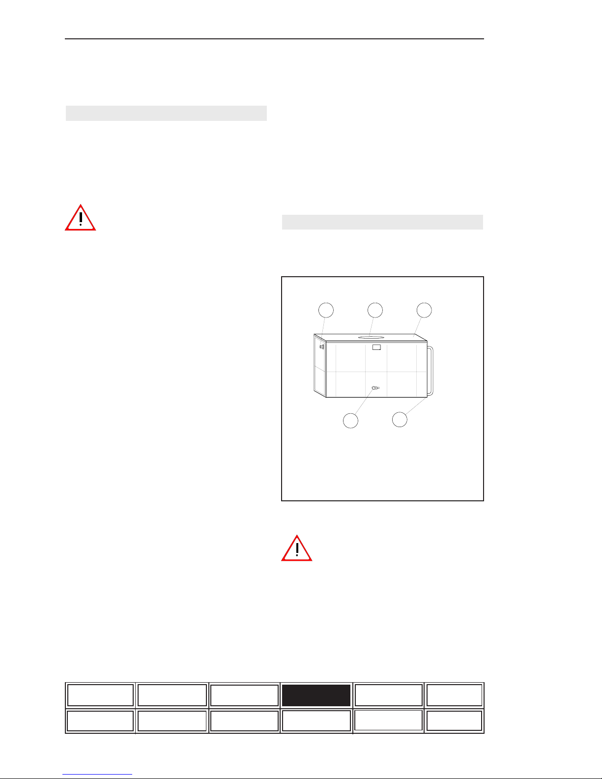
4. Description of the unit
1 Exhaust air socket
2 Program control system
3 Data and print key
4 The test chamber becomes
accessible by unlocking the door
and swinging it to the side
5 Access to ultra-pure water tank
Unit set-up
Unit description
List of options
and accessories
Start-up
Care and cleaningTest set-up
Program example on
XENOTEST BETA
XENOTEST BETA
Features
Safety hints
Function
Options and accessory
of the XENOTEST BETA
6 Height adjustable feet
7 Test chamber door
8 Keyboard for program input
9 Key operated switch, START/STOP key
10 4-line LCD-display providing operator
guidance and data information
4.1 Front side of equipment (fig. 3)
Figure 3: Front side of equipment
Maintenance
XENOTEST BETA LM
10
9
8
7
65
4
3
2
1
Page 15
ATLAS Operating manual XENOTEST BETA LM
Page 15
Unit set-up
Unit description
List of options
and accessories
Maintenance
Start-up
Care and cleaningTest set-up
Program example on
XENOTEST BETA
XENOTEST BETA
Features
Safety hints
Function
Options and accessory
of the XENOTEST BETA
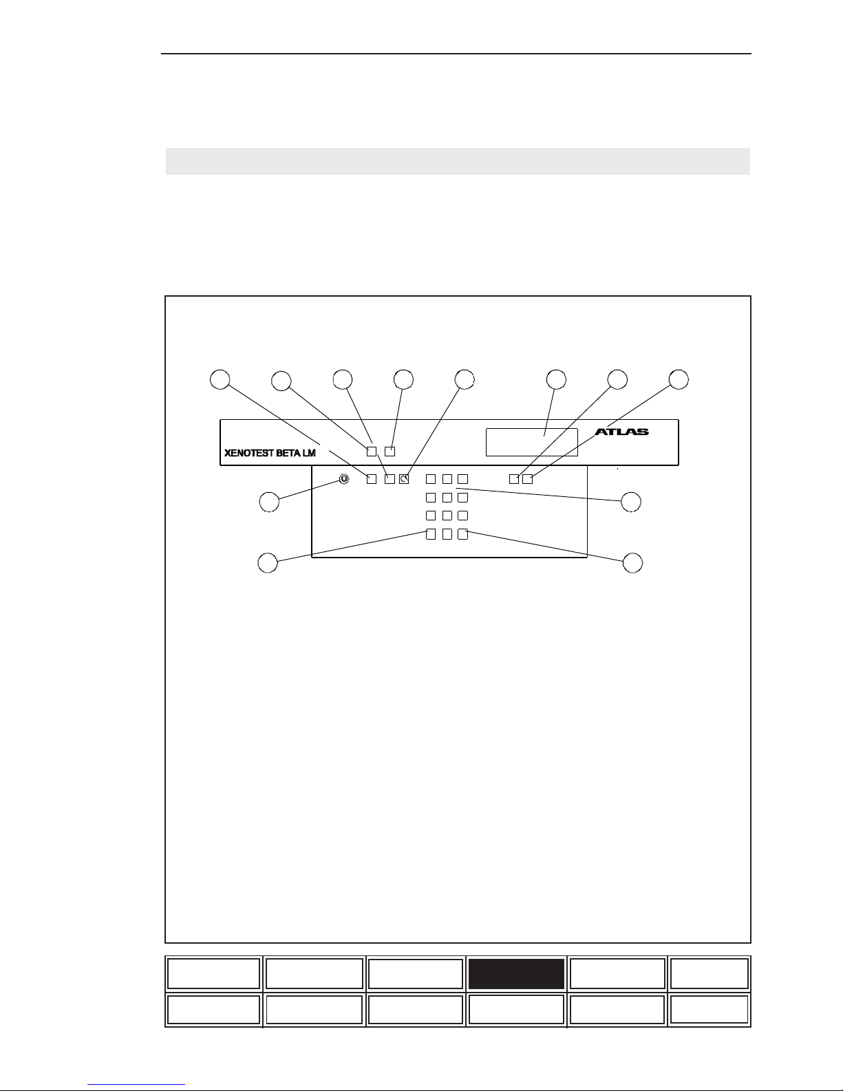
9 Green LED light comes on when
main switch is on
10 STOP key
11 Red LED flashes when the program is
interrupted with the STOP key or when
the system is defective. The red LED is
continuously on when certain limit values
are exceeded
12 Key to interrupt the rotation of the
specimen holder carousel during a running
program resp. to move the carousel when
a program is interrupted
4.1.1 Program control (fig. 4)
The control panel on the front side of the apparatus
controls and regulates the course of the input
weathering program. The program keyboard can be
locked during operation of the machine against
unauthorized access by means of a key-operated
switch.
Figure 4: Program control
1 4-line LCD display for user
guidance and data display
2 Data key for data display
3 Print key to print out the stored
program, parameter measurements
and system status from the printer
4 Program input keyboard
5 Enter key to confirm the input values
6 Escape key
7 Key-operated switch to allow locking
of the keyboard when the system is
running
8 START key
1
2
3
4
56
7
8
9
10
11
12
0
1
Start
Sto p
1
23
456
789
0
ESCAPE ENTER
DATA PRINT
Page 16
Operating manual XENOTEST BETA LM ATLAS
Page 16
Unit set-up
Unit description
List of options
and accessories
Start-up
Care and cleaningTest set-up
Program example on
XENOTEST BETA
XENOTEST BETA
Features
Safety hints
Function
Options and accessory
of the XENOTEST BETA
To clean the test chamber the specimen carousel
(10) is disassembled. For this, the 4 securing
screws of the top and bottom carousel rack (11/
12) are removed and the racks are placed on the
test chamber bottom. Unscrew the 4 securing
screws (13) of the four carousel bows (14) and
remove the bows from the test chamber. Finally
remove the two air routing plates (15) from the
Figure 5: Water tank
3
1
2
4
5
test chamber.
4.1.3 Water tank (fig. 5)
The water tank is placed in the bottom part of the
apparatus and provides for the supply with ultrapure water for the humidity and rain functions (see
fig. 11 water circuits).
1 Tank cover
2 Aperture for hose connections
3 Inlet socket
4 Outlet socket
5 Water level indicator
Water quality
The water quality must be of high-grade purity to
prevent deposits building up on the optical
filter system, the internal walls and the
samples. Deposits will alter the exposure
results. The use of ion exchange cartrid-
ges alone is not sufficient.
Regarding the water purity we refer to the minimum requirements of some important standards,
such as DIN 53387 „Light exposure and weathering of plastics“:
1. Electrical conductivity: < 5 µS/cm
2. PH value: 6-8
3. Content of solid bodies < 1 ppm measured
as silicon dioxide
Maintenance
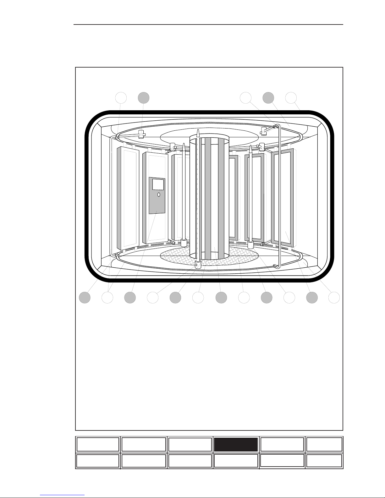
4.1.2 Test chamber (fig. 6)
The test chamber becomes accessible after unlocking the test chamber door and swinging it to
the side. It is equipped with a safety switch allowing to switch off the machine during a running
program.
This safety switch must be checked for its
perfect technical function within the determined inspection intervals, or at least once
a year.
Are located in the centre of the test chamber the
selected outer cylinder (1) with the three xenon
lamps (2) and the filter lantern (3).
The 16 sample holders (4) are latched into the
two carousel racks (5) and during operation rotated around the lamps and the filter lantern.
Test chamber and xenon lamps are supplied by
separate air flows. A uniform air ventilation over the
specimen surface is achieved by an appropriate airflow above and below the specimen carousel (fig.
10 ventilation scheme). At the bottom rear of the
test chamber two connection hoses are provided
which supply the two humidifiers with air. The maximum chamber humdidity can be adjusted up to
95% r.h. depending on the preset temperature.
The rain bars (6) mounted in the test chamber
spray ulra-pure water in cyclical intervals and without any pressure from the water tank on to the spe-
cimens (7). The bars can be withdrawn from the
test chamber by pressing on the unlocking base
(8) at the bottom end of the rain bar. A so-called
XENOSENSIV sensor (9) is installed on a samp-
le holder by means of a special adapter to measure the irradiance in the range between 300-400nm
and the black standard temperature in the surface
temperature range up to 130°C. If no sensor is used
the end plug must be fitted.
A sensor is mounted in the upper rear part of the
test chamber which measures the test chamber
temperature and the relative humidity. The sensors
combined with the program control guarantee control of constant setting values.
Page 17
ATLAS Operating manual XENOTEST BETA LM
Page 17
Maintenance
Unit set-up
Unit description
List of options
and accessories
Start-up
Care and cleaningTest set-up
Program example on
XENOTEST BETA
XENOTEST BETA
Features
Safety hints
Function
Options and accessory
of the XENOTEST BETA
Figure 6: Test chamber
1
2
3
4
5
6
7
8
9
10
11
12
13
14
15
16
17
Maintenance
10 Specimen carousel
11 Securing screws,
carousel rack bottom (4x)
12 Securing screws, carousel rack top (4x)
13 Securing screws carousel bow (4x)
14 Carousel bows (4x)
15 Air routing plates, bottom
16 Air routing plates, top
17 Door sealing of test chamber
1 Outer cylinder
2 Xenon lamps NXE 2200 (3x)
3 Filter lantern
4 Sample holder (16x)
5 Specimen carousel rack (2x)
6 Rain bar (3x)
7 Specimen
8 Unlocking base
9 XENOSENSIV sensor
Page 18

Operating manual XENOTEST BETA LM ATLAS
Page 18
Unit description
List of options
and accessories
Care and cleaningTest set-up
Program example on
XENOTEST BETA
XENOTEST BETA
Features
Safety hints
Options and accessory
of the XENOTEST BETA
A thermoprinter (2) is placed above the main
switch providing for the print-out of data of the stored
programs as well as of the actual measuring values
of the current program.
The interface (3) on the right-hand side of the main
switch provides for the data output and external
computer control.
Right to the test chamber (4) is the climatic duct
(5) with the integrated heating (6) to warm up the
test chamber air. The two air flap motors (7) serve
to adjust the air flaps in the ventilation duct (8).
The climatic fan (9) recirculates the air and is
controlled by the climatic fan control (10).
The operating hour counter (11) counts the
operating time of the equipment.
The three power supply units (13) of the lamps
are placed behind a protective wire mesh (12).
0
1
4.2 Right hand apparatus side
(fig.8)
The mains switch (1) (fig. 7) is located at the top
left; disconnect unit in case of trouble.
The unit must be disconnected for all maintenance
works. Turn switch to position "0", and pull
mains plug. Protect against replugging!
Figure 7: Main switch
Maintenance
Start-upUnit set-up
Function
High voltage is present on the power packs.
Touching may be hazardous to your life !
The fuse for the heating (14) and the fuses for
the three lamps (15) are located below the
protective wire mesh. The fuse protection for the
three lamps is 25 amps and for the heating it is 16
amps.
4.3 Apparatus top (fig. 8)
The separate exhaust air flows for lamp cooling and
test chamber warming are evacuated at the top of
the unit via separate exhaust air sockets to the open
(see fig. 11 ventilation scheme). Exhaust air sok-
ket lamp cooling (16) diameter 100mm, exhaust
air socket test chamber warming (17) diameter
200mm.
The hoses for the lamp and test chamber
exhaust air must be made of flexible heatresisting material, as the temperatures of
the exhaust air may reach up to a max. of
120°C.
The max. length of the exhaust hose is li-
mited to 3m including the option of two 90
degree bends. In case of longer exhaust
air ducts or with more than two 90 degree
bends an external blower is needed.
Page 19

ATLAS Operating manual XENOTEST BETA LM
Page 19
Unit description
List of options
and accessories
Care and cleaning
Program example on
XENOTEST BETA
XENOTEST BETA
Features
Function
Options and accessory
of the XENOTEST BETA
After the opening of the lateral two-leaf doors the right side of the apparatus becomes accessible.
1
2
3
4
5
6
7
8
11
12
13
14
16
9
10
15
17
18
0
123456
Figure 8: Right side of unit
Maintenance
Start-up
Safety hints
Unit set-up
Test set-up
1 Mains switch
2 Thermoprinter
3 Interface RS 232 / RS485
4 Test chamber
5 Climatic duct
6 Heating (4x)
7 Air flap motor
8 Ventilation duct
9 Climatic fan
10 Control climatic fan
11 Operating hours meter
12 Protective wire mesh
13 Power supply units for lamps (3x)
14 Fuse heating, 1 piece, 16A
15 Fuse lamps, 3 pieces, 25A
16 Exhaust air socket lamp cooling
17 Exhaust air socket test chamber heating
18 Mains adaper transformers (3x)
Page 20

Operating manual XENOTEST BETA LM ATLAS
Page 20
4.4 Left hand apparatus side
(fig. 9)
The fan to cool down the lamps (1) is seated
below the test chamber. At the same level on the
left side the two humidifiers (2) are fitted. The
water supply to the two humidifiers can be adjusted
by means of a valve (3). Via two fexible, heat
resistant hoses (4) the humidifiers are supplied
with air out of the test chamber and direct the
humidified air via 8 outlets (5) to the ventilation
duct. From there the humidified air is inserted to
the test chamber by means of a fan (see fig. 11
ventilation scheme).
The sensor for the test chamber temperature and
the rel. humidity transmits the actual values taken
from the exhaust air flow of the test chamber to
the program control system. With a target/actual
comparison the requested test parameters are
adjusted permanently by adjusting aggregates.
With an inserted XENOSENSIV sensor (see fig.
6.9) a slip ring collector (7) transmits the
measured values to the program control. The rain
pump (8) provides the three rain bars with pure
water.
The inlet and outlet lines of the humidifier, the
water return line from the test chamber and the
supply line of the water pump are led through the
top of the water tank (9).
The ignition units (10) in conjunction with the
power supply units ignite the xenon lamps.
4.5 Apparatus rear panel
(fig. 9)
Unit description
List of options
and accessories
Care and cleaningTest set-up
Program example on
XENOTEST BETA
XENOTEST BETA
Features
Safety hints
Options and accessory
of the XENOTEST BETA
Maintenance
Start-up
Unit set-up
Function
An opening for the air supply flow is provided on
the upper rear panel of the apparatus. The laboratory air is cleaned by a filter mat (11) .
Page 21

ATLAS Operating manual XENOTEST BETA LM
Page 21
After the opening of the lateral two-leaf doors the left side of the apparatus becomes accessible.
8 Rain pump
9 Water tank
10 Power supply lamps (3x)
11 Filter mat
12 Water inlet water tank
13 Water outlet water tank
14 Height adjustable feet
3
4
5
6
7
8
9
10
11
12
13
2
14
1
Figure 9: Left side of the unit
Unit description
List of options
and accessories
Care and cleaningTest set-up
Program example on
XENOTEST BETA
XENOTEST BETA
Features
Safety hints
Options and accessory
of the XENOTEST BETA
Maintenance
Start-up
Unit set-up
Function
1 Fan lamp cooling
2 Humidifier (2x)
3 Valve
4 Hose (2x)
5 Air outlet humidifier (8x)
6 Sensor for test chamber
temperature and rel. humidity
7 Slip ring collector
Page 22

Operating manual XENOTEST BETA LM ATLAS
Page 22
1
2
3
4
5
6
7
8
9
10
11
12
13
14
15
16
17
Figure 11: Ventilation scheme
4.6 Ventilation circuits (fig. 10)
1) Lamp cooling:
Fan (1) produces the exhaust air flow (2), which
cools down the xenon lamps.
2) Test chamber (fresh air operation):
The ventilation circuit of the test chamber receives
fresh air (3) through a filter mat (4) at the rear
panel of the unit. The quantity of fresh air is
controlled by a flap air inlet (5) and warmed up
with a heating system (6). The climatic fan (7)
transmits the air humidified by the humidifier (8)
via air leading plates (9) to the test chamber. The
air intake tube for the humidifier (10) takes its
air out of the test chamber.
There is a uniform air flow around the samples
(11). A sensor (13) measures the temperature and
rel. humidity of the test chamber exhaust air (12)
under permanent target/actual comparison. Via
exhaust air sockets (14) the air is evacuated to
the outside.
3) Test chamber (air circulation):
During the air circulation mode the air flaps (15)
are closed within the flap adjusting range (16)
and the air flow (17) is directed as described.
Unit description
List of options
and accessories
Care and cleaningTest set-up
Program example on
XENOTEST BETA
XENOTEST BETA
Features
Safety hints
Options and accessory
of the XENOTEST BETA
Start-upUnit set-up
Function
1 Fan lamp cooling
2 Exhaust air from lamps
3 Air inlet
4 Filter mat
5 Flap air inlet
6 Heating
7 Fan
8 Humidifier
9 Air leading plates
Maintenance
10 Air inlet hose humidifier
11 Sample
12 Exhaust air from test chamber
13 Sensor for test chamber temperature and
rel. humidity
14 Exhaust air socket
15 Flaps
16 Flaps adjusting range
17 Circulated air
Page 23

ATLAS Operating manual XENOTEST BETA LM
Page 23
5.1 Options
Unit components which are installed by Xenotest GmbH.
5.1.1 Rain, humidity function and sample back cooling (fig. 11)
1 Water tank
2 Water inlet socket
3 Level switch
4 Solenoid switch
5 Diving pump (2x)
6 Humidifier (2x)
7 Valve
8 Rain pump
9 Rain bar (3x)
10 Pump for sample back cooling
11 Spray nozzle for sample back cooling
12 Water inlet hose
13 Water reverse hose
14 Water outlet socket
1
3
5
2
4
6
7
8
9
11
10
13
14
12
5. Options and accessories of the XENOTEST BETA
Figure 11: Water circuits
Unit set-up
Unit description
List of options
and accessories
Care and cleaningTest set-up
Program example on
XENOTEST BETA
XENOTEST BETA
Features
Safety hints
Function
Options and accessory
of the XENOTEST BETA
Start-up
adjustable by a valve (7). The rain pump (8)
supplies water to the rain bars (9). The pump (10)
supplies water through the supply lines (12) to
the spray nozzles for the sample back cooling
(11) . Excess water is returned to the water tank
via a reverse hose (13) or evacuated outside. The
water tank can be emptied by the water outlet
socket (14).
The water tank (1) is filled through a water inlet
socket (2) (see chapter 4.1.3 on water quality).
The overflow is regulated by a level switch (3),
water shortage is indicated by a solenoid switch
(4) on the display. Two diving pumps (5) are
located in the water tank which supply the two
humidifiers (6) with water. The supply amount is
Maintenance
Page 24

Operating manual XENOTEST BETA LM ATLAS
Page 24
LED-Alarm:
Lighting up of the LED signals the end of the
printing paper.
Line Feed/Enter:
This key has two functions. During operation „Line
Feed“ is used for manual paper transport, in the
menu program, „Enter“ is used to take over and
store the parameters chosen with „Select“.
By pressing the locking latch to the right the
frontplate swings out. This provides access to the
paper roll for exchange.
Figure 12: Printer
1
2
3
4
5
The stored programs and the measured data for
the program activated can be printed out by the
thermal printer. By pressing the „PRINT“-key during
the running program the printer parameters are
indicated on the display:
Equipment data = 1
Program parameter = 2
Current parameter = 3
5.1.2 Printer (fig. 12)
The requested parameters are entered via the
keyboard of the control panel. When selecting
menu item 3 „Current parameters“ the printout
interval in minutes can be entered via the keyboard.
1 LED „ALARM“
2 Key LINE FEED/ENTER
3 Locking latch
Unit set-up
Unit description
List of options
and accessories
MaintenanceCare and cleaningTest set-up
Program example on
XENOTEST BETA
XENOTEST BETA
Features
Safety hints
Function
Options and accessory
of the XENOTEST BETA
Start-up
4 Key MENU/SELECT
5 Paper tear-off bar
Menu/Select
This key has two functions. If this key is depressed
for more than 3 seconds during operation the
printer willl change to the menu program alllowing
modification of the printer parameters. In the menu
program "Select" is used to chose the various
equipment parameters.
Maintenance
Page 25

ATLAS Operating manual XENOTEST BETA LM
Page 25
Basic parameters of the printer (fig. 13)
The basic parameters were preset in the factory as follows:
Paper tear-off bar :
To tear off the paper strap, tear paper quickly
upwards from one side to the other.
Unit set-up
Unit description
List of options
and accessories
MaintenanceCare and cleaningTest set-up
Program example on
XENOTEST BETA
XENOTEST BETA
Features
Safety hints
Function
Options and accessory
of the XENOTEST BETA
Start-up
The printer parameters (fig. 13) are preset
in the factory, and must not be changed.
Change of printer parameters: (fig. 14)
1. For access to the menu, press
„MENU/SELECT“ key for more than 3 seconds.The
following message will be printed out.
ACTUAL PARAMETER? PRESS „ENTER“
2. Press „LINE FEED/ENTER“ key. The printer
prints out current parameters and shows the
following message.
CHANGE OF PARAMETERS?
3. To change the printer parameters, press
„LINE FEED/ENTER“ and „MENU/SELECT“ for
more than 4 seconds. Afterwards the single
parameters are listed and can be confirmed by
pressing „LINE FEED/ENTER“ or be changed by
pressing „MENU/SELECT“.
4. To exit the menu programm, press „MENU/
SELECT“ and „LINE FEED/ENTER“ keys
simultaneously, or the program is automatically
terminated after 3 minutes without actuating any
key.
Figure 13: Printer parameters
PRINT INTERVAL
PRINTER ADDRESS
DATA FORMAT
BAUDRATE
INTERFACE
CHARACTER SET
CHARACTERS/LINE
PRINT FORMAT
PRINT STRENGTH
MODE
NO
00-PRINT ALWAYS
8 NO PARITY
INVERSE
ON LINE
40
2400
SERIAL
NATIONAL LANGUAGE
.....+.....
Page 26

Operating manual XENOTEST BETA LM ATLAS
Page 26
Figure 14: Printer scheme
Unit set-up
Unit description
List of options
and accessories
MaintenanceCare and cleaningTest set-up
Program example on
XENOTEST BETA
XENOTEST BETA
Features
Safety hints
Function
Options and accessory
of the XENOTEST BETA
Start-up
Page 27

ATLAS Operating manual XENOTEST BETA LM
Page 27
Figure 15
5.1.4 Interface (fig. 17)
The unit supports an RS 232 or RS 485 interface
alternatively to give out measurement data to a
computer whilst a program is in progress.
With the accessory-package XENOVIEW consisting of:
- connection cable
- software
- operating manual
the interface can be driven.
(seriell 9-pole Id. No. 56076813)
(seriell 25-pole Id.-No. 56076812)
Connect the interface of the unit with the seriell
interface of the computer.
Unit set-up
Unit description
List of options
and accessories
MaintenanceCare and cleaningTest set-up
Program example on
XENOTEST BETA
XENOTEST BETA
Features
Safety hints
Function
Options and accessory
of the XENOTEST BETA
Start-up
Change of paper roll: (fig.15)
1. Press locking latch to the right and swing
front panel open.
2. Remove old paper roll.
3. Fit new paper roll in such way that it turns
clockwise when unwinding.
4. Cut edges of the paper and insert paperroll (note fig. 15).
5. Keep „LINE FEED/ENTER“ key
depressed until the beginning of the paper
appears below the tear-off edge.
6. Close front door (locking latch must
engage), the LED "ALARM" will go out,
and the printer is ready for operation.
5.1.3 Mains transformers
(fig.16)
The mains transformers are needed for specific
mains adaptations in the various countries and are
fitted to the lower, right side of the unit. (see fig.
8.18).
Roll
Paper inlet slot
Figure 16
Figure 17: Software Xenoview
Page 28

Operating manual XENOTEST BETA LM ATLAS
Page 28
Figure 18: XENOCHROME filter system and path of radiation
Useful lifetime:
The XENOCHROME filters are very resistant to
ageing, and their recommended lifetime is 25,000
hours. The filters are exchanged as complete set
and for distinction are marked at the lower filter
end with the numbers I,II,III or 270, 300 und 320.
Different irradiance values can be obtained by
varying the optical filter system (see figs. 19 and
20).
Path of radiation:
The fraction of UV and light radiation which come
into contact with the coated filters pass through
the outer cylinder towards the specimen level, while
the IR-radiation parts are reflected and directed
on to the black metal absorber which absorbs them.
The air flow along the xenon lamps and the
absorber plates in the optical filter system
dissipates the heat.
UV + VIS
UV + VIS
IR
IR
1
2
3
4
5
5.2.1 Filter system
The XENOTEST BETA is used to simulate the solar or global spectrum with filtered xenon lamp radiation. To realise the various standards and test
specifications a XENOCHROME filter system is
at your disposal.
The XENOCHROME filter system (fig. 18) consists
of a filter lantern (2) with three absorbers (3)
staggered by 120°, and 10 filters (4) with the
corresponding outer cylinder (5).
A) XENOCHROME 270 (I) with quartz glass
cylinder,
B) XENOCHROME 300 (II) with special UV
glass cylinder (Suprax),
C) XENOCHROME 320 (III) with special UV
glass cylinder, (Suprax).
5.2 Accessories
Helpful accessories for the operation with XENOTEST BETA LM:
Unit set-up
Unit description
List of options
and accessories
Care and cleaningTest set-up
Program example on
XENOTEST BETA
XENOTEST BETA
Features
Safety hints
Function
Options and accessory
of the XENOTEST BETA
Start-up
Maintenance
1 Xenon lamp (3x)
2 Filter lantern
3 Absorber (3x)
4 Filters (10x)
5 Outer cylinder
Page 29

ATLAS Operating manual XENOTEST BETA LM
Page 29
Figure 19: Spectral energy distribution in the wavelength range 200-800 nm
XENOCHROME 300 filter system with Suprax outer cylinder and CIE 85
Figure 20: Spectral energy distribution in the wavelength range 200-800 nm
XENOCHROME 270 filter system with outer quartz cylinder
XENOCHROME 320 filter system with Suprax outer cylinder
Unit set-up
Unit description
List of options
and accessories
Care and cleaningTest set-up
Program example on
XENOTEST BETA
XENOTEST BETA
Features
Safety hints
Function
Options and accessory
of the XENOTEST BETA
Start-up
Maintenance
0
2
4
6
8
10
12
200 300 400 500 600 700 800
Wellenlänge [nm]
Bestrahlungsstärke [W/m² x nm]
Xe nochrome 300
CIE 85
0
2
4
6
8
10
12
200 300 400 500 600 700 800
Wellenlänge [nm]
Bestrahlungsstärke [W/m² x nm]
Xeno c hrome 320
Xeno c hrome 270
Page 30

Operating manual XENOTEST BETA LM ATLAS
Page 30
To make contrast between the irradiated and nonirradiated sections of the specimen clearly visible,
cover plates are available with 3 differently sized
apertures of 9mm, 18mm und 27mm.
Fitting: At first the cover plate is inserted into the
sample holder, followed by the specimen which is
then fixed by means of the spring-operated clamps.
Figure 22: Cover plates
5.2.4 Exposure cards
Certain standards specify the make-up of the
specimens, e.g. point 5 of DIN 54004 requires the
specimen to be secured to a card.
100 exposure cards with the dimensions 80mm x
320mm x 0,05mm (No. 56076547).
5.2.5 Cover plates (fig. 22)
5.2.2 Standard sample holder
set (fig.21)
The standard sample holder set consists of 16
sample holders with the dimensions 320mm x
80mm x 10mm maximum sample thickness (no.
56076543). For the fitting of thin, unstable samples
in the sample holder a set of 16 fixing sheets is
enclosed.
Fitting: First place the specimen in the sample holder. Afterwards the fixing sheet is put on and fixed
with the spring-operated clamps.
Unit Sample
holder
Sample / Dimensions
Length x Width x
Thickness
XENOTEST
1200
16 3 samples
100mm x 68mm
x 10mm
XENOTEST
ALPHA
150 / 150S
28 2 samples
135mm x 45mm
x 10mm
Figure 21: Sample holder set standard
5.2.3 Special sample holder
Special sample holders are used to insert different
sample dimensions within the XENOTEST series.
Unit set-up
Unit description
List of options
and accessories
Care and cleaningTest set-up
Program example on
XENOTEST BETA
XENOTEST BETA
Features
Safety hints
Function
Options and accessory
of the XENOTEST BETA
Start-up
Maintenance
Page 31

ATLAS Operating manual XENOTEST BETA LM
Page 31
5.2.8 Calibration adapter and
end plug
To calibrate the XENOSENSIV sensor (chapt. 6.5)
a calibration adapter (fig. 27) is used. If no sensor
is inserted, the contact plug in the test chamber is
secured by means of an end plug (chapt. 6.6,
fig.28).
5.2.6 XENOSENSIV sensor
(fig. 23)
The XENOSENSIV sensor collects the values of
irradiation in a wavelength range of 300-400 nm as
well as the values of the black standard temperature
in a surface temperature range up to 130 °C at
specimen level.
The XENOSENSIV sensor enables constant regulation of chosen irradiation and black standard
temperature values.
Figure 24: Support sheet
Figure 23: XENOSENSIV sensor
5.2.7 XENOSENSIV sensor
support sheet (fig. 24)
The support sheet is used to fix the XENOSENSIV
sensor in the test chamber.
Unit set-up
Unit description
List of options
and accessories
Care and cleaningTest set-up
Program example on
XENOTEST BETA
XENOTEST BETA
Features
Safety hints
Function
Options and accessory
of the XENOTEST BETA
Start-up
Maintenance
Page 32

Operating manual XENOTEST BETA LM ATLAS
Page 32
6.1 Insert filters into lantern
Wear cotton gloves to insert the filters in
order to avoid finger prints on the glass.
The 11 filters of the XENOCHROME-filter system
are carefully inserted from the top and are turned
to the fitting position.
6.2 Insertion of the XENOTEST light exposure
system (fig. 25)
The light exposure system includes:
1 Outer cylinder
2 Filter lantern
3 Lamps
Outer quartz cylinder: for
XENOCHROME 270 filter system,
Special UV glass filter (Suprax): to be
used for XENOCHROME 300 and 320
filter system.
The external cylinder is inserted as follows:
6. Start-up
8. open the test chamber door and move
the connection piece of the unscrewed
flange tube slightly upwards,
9. fit lower sealing ring (9) and insert ex-
ternal cylinder (10) of your choice from
the front through the test chamber door,
10. insert upper sealing ring (11) into connection piece and slide this on external
cylinder and sealing ,
11. fix upper flange with 4 securing screws
from top through casing cover,
take care of the alignment of the external cylinder,
12. place filter lantern into the outer cylinder,
13. wear gloves to carefully push the three
xenon lamps into the bottom lamp sockets.
Take care to correctly align the distance
between absorber and lamps,
14. fit the lamp centering piece.
15. The cables of the lamp contacts are
provided with numbers (see fig. 25).
Absolutely take care that the contacts
are connected to the corresponding
lamps. Incorrect connection may
damage the equipment or lead to injury
of the user.
16. Finally fit the exhaust tube such that
the lamp cables get seated in the
corresponding recess.
17. Close the casing cover and place the
flexible exhaust tube on to the air exhaust
adapter.
When opening the casing cover on the unit top the
light system is switched off. After closing
the lid, the system must be re-ignited to
continue the exposure.
The door safety switch has to be checked for its
safety functions within the stipulated proof
intervals, or at least once a year.
Unit set-up
Unit description
List of options
and accessories
Care and cleaningTest set-up
Program example on
XENOTEST BETA
XENOTEST BETA
Features
Safety hints
Function
Options and accessory
of the XENOTEST BETA
Start-up
Maintenance
1 . Disconnect unit from mains (pull
mains plug),
2. remove exhaust air pipe on top of unit,
open cover locking and fold up cover (1),
loosen spacer tube (2) and put on the
side,
3. put contacts (3) of the lamps on the side,
4. remove lamp centering piece (4),
5. wear gloves to carefully remove lamps (5),
6. remove filter lantern (6),
7. unscrew the 4 securing screws (7) of
the flange tube (8),
Page 33

ATLAS Operating manual XENOTEST BETA LM
Page 33
1
2
3
4
5
6
7
8
9
10
11
2
10
26
27
28
Figure 25: Insertion of the XENOTEST exposure system
Unit set-up
Unit description
List of options
and accessories
Care and cleaningTest set-up
Program example on
XENOTEST BETA
XENOTEST BETA
Features
Safety hints
Function
Options and accessory
of the XENOTEST BETA
Start-up
Maintenance
1 Casing cover
2 Spacer tube
3 Lamp contacts
4 Lamp centering piece
5 Xenon lamps (3x)
6 Filter lantern
7 Securing screws flange tube (4x)
8 Flange tube
9 Bottom sealing ring
10 Outer cylinder
11 Top sealing ring
Page 34

Operating manual XENOTEST BETA LM ATLAS
Page 34
6.2.1 Inserting the lamps and
the filter lantern
To exchange the lamps and the filters proceed as
described in chapter 6.2 for the start-up:
Exchange of lamps: points 1-5, 13-17.
Exchange of filter lantern: points 1-6, 12-17.
6.2.2 Exchange of lamps
To optimize the radiation constancy the lamps are
exchanged in a 500-hour interval.
Before starting operation of the equipment set the
lamp age of lamp 1 to 1000 hours, lamp 2 to 500
hours and lamp 3 to 0 (see software documentation).
The recommended exchange after 500 operating
hours is signalled by the program control.
The lamp age can be retrieved via the DATA key
while the program is running.
The correspondence of the lamps to the numbered
connection cables is as follows:
Lamp 1 = left - (cable-number 26),
Lamp 2 = centre - (cable-number 27),
Lamp 3 = right - (cable-Number 28).
Unit set-up
Unit description
List of options
and accessories
Care and cleaningTest set-up
Program example on
XENOTEST BETA
XENOTEST BETA
Features
Safety hints
Function
Options and accessory
of the XENOTEST BETA
Start-up
Maintenance
The cables of the lamp contacts are
provided with numbers (see fig. 25).
Absolutely take care that the contacts
are connected to the corresponding
lamps.
Operating
hour s
Lamp 1
Left
No. 26
Lamp 2
Middle
No. 27
Lamp 3
Rig ht
No. 28
500
X
1000
X
1500
X
2000
X
2500
X
and so on
X
6.3 Water supply
For the humidity and rain functions ulta-pure water
is needed. A supply line with a pressure-resistant
hose (inner diameter 13 mm, 3 bar ) leads the water
into the water tank (fig. 5). When the tank is full, the
line is closed by a float valve. Any water shortage
occurring in the tank is notified to the control system
via a solenoid and shown on the display.
If no supply line is present the tank can be filled
manually after opening the bottom door at the front
side of the unit.
To ensure the function of the water circulation and
humidifcation systems the unit must be
aligned by means of its height adjustable
feet (fig. 3.6). Please take care of the
necessary water quality (chap. 4.1.3)!
6.4 Insert the XENOSENSIV sensor (fig. 26)
The XENOSENSIV sensor (3) is fixed with the
fixing screws (1) to the support sheet (2). The
mounted sensor is then fitted on a sample holder
and inserted on the left or right side of the connection cable into the carousel.
Connect the connection plug to the coupling in the
test chamber by means of the connection cable
(4). The continuously rotating sensor (at sample
level) collects the measuring values of the black
standard temperature (5) in the range of the ambient temperature up to 130°C at sample level as
well as the measuring values of the irradiance
(6) in the wavelength range of 300-400nm .
The measuring values are used by the program
control to adjust the preset parameter values.
Page 35

ATLAS Operating manual XENOTEST BETA LM
Page 35
Figure 26: Insertion of the XENOSENSIV sensor
4 Connection cable
5 Measuring of black standard temperature
6 Irradiance measuring
1 Fixing screw (2x)
2 Support sheet
3 XENOSENSIV sensor
Unit set-up
Unit description
List of options
and accessories
Care and cleaningTest set-up
Program example on
XENOTEST BETA
XENOTEST BETA
Features
Safety hints
Function
Options and accessory
of the XENOTEST BETA
Start-up
Maintenance
5
3
2
1
4
6
Page 36

Operating manual XENOTEST BETA LM ATLAS
Page 36
1 Master sensor socket
2 XENOSENSIV sensor socket
3 Plug-type connector
Figure 27: Calibration adapter
Figure 28: End plug
6.6 Insertion of the end
plug (fig. 28)
If no XENOSENSIV sensor is fitted, the coupler
socket in the test chamber is secured with an
adapter plug.
S
S
T
E
1
2
3
Unit set-up
Unit description
List of options
and accessories
Care and cleaningTest set-up
Program example on
XENOTEST BETA
XENOTEST BETA
Features
Safety hints
Function
Options and accessory
of the XENOTEST BETA
Start-up
For special weathering procedures a dew effect can
be produced on the sample surface. This is achieved after changing over from the exposure phase
to the dark cycle under especially selected conditions of temperature and humidity and under simultaneous spraying of the sample backs. (Dropping below the dew point).
In order to achieve an efficient sample cooling, the
samples are placed on the sample holders unbacked.
6.7 Sample back cooling
Maintenance
6.5 Calibration of the XENOSENSIV sensor
For the calibration of the XENOSENSIV sensor two
sensors, namely the master and the XENOSENSIV sensor, are placed in the test chamber on two
adjacent sample holders. The sensors ae then interconnected by means of the calibration adapter
(fig. 27).
Care must be taken that the input sockets
of the calibration adapter are tied up to the
corresponding sensors.
Then connect the plug-type connector of the adapter to the connection cable of the program control.
Set the switch of the adapter to BST for calibration
of the black standard temperature or to E for the
irradiance. The calibration program can then be started.
Page 37

ATLAS Operating manual XENOTEST BETA LM
Page 37
7. Function
7.1 Measuring and control
sensor system
The integrated sensor system of the XENOTEST
BETA together with the sensor for test chamber
temperature and relative humidity (fig. 29) and the
XENOSENSIV sensor covers the following items:
1. measuring of the irradiance at sample
level in a range between 300 and 400nm,
2. control and display of the irradiance be-
tween 35 (min.) and 165 W/m² (max.),
depending on the selected filters,
3. measuring of the black standard
temperature at sample level,
4. control and display of the black standard
temperature between ambient °C and
130°C,
5. measuring, control and display of the
test chamber temperature,
6. measuring, control and display of the
rel. humidity.
without XENOSENSIV sensor:
1. control by the relative electrical lamp
power (0 or 53-120%).
100% lamp power corresponds to a nominal power of 2200 VA. The control range
from 100-120% allows for the lamp ageing.
2. Control by test chamber temperature
(ambient °C to 80°C).
Unit set-up
Unit description
List of options
and accessories
Care and cleaningTest set-up
Program example on
XENOTEST BETA
XENOTEST BETA
Features
Safety hints
Function
Options and accessory
of the XENOTEST BETA
Start-up
Screws
Sensor head
Housing
Mounting
Figure 29: Sensor for test chamber
temperature and rel. humidity
Maintenance
7.1.1 Control of the irradiance
The irradiance can be measured in a wavelength
range between 300-400nm and - depending on the
selected filters - can be set in a range between a
min. of 35 to a max. of 165 W/m². During the lifetime of the lamp (1500 hours) the irradiance is kept
constant at the set value.
The irradiance is infinitely variable by the program
control (fig. 4). Deviations of the irradiance are
identified by the XENOSENSIV sensor and
compensated by the electronic control system.
Depending on the selected filter configuration different spectral energy distributions may occur
(figs.19, 20).
7.1.2 Control of the black
standard temperature
The adjustable black standard temperature depends
on the ambient temperature and on the irradiance.
The setting scope covers a range between ambient
temperature and a max.of 130°C. It is measured
with the XENOSENSIV sensor. It is adjusted by
the speed of the test chamber fan, i.e. by the air
flowrate in the test chamber.
7.1.3 Control of the fan speed
The fan speed can be varied in a range between
800-2500 rpm. Adjustment is effected by the program control (chap.8.6). A variation of the fan speed
automatically changes the black standard temperature which results from the preset irradiance, test
chamber temperature and selected filter system.
To increase the black standard temperature it is
necessary to reduce the fan speed and vice versa.
Page 38

Operating manual XENOTEST BETA LM ATLAS
Page 38
The test chamber temperature is measured in the
air flow and then displayed. By adding air of the
laboratory and in conjunction with the heating
aggregate the test chamber temperature can be
controlled in a range from ambient °C to 80°C.
7.1.5 Control of the test chamber humidity
7.2 Rain
The rain sprinkling of the entire sample surface is
pressureless and is provided by three rain bars
placed in the test chamber.
7.3 Sample back cooling
The sample back cooling comes from spray
nozzles provided in the test chamber wall.
7.1.4 Control of the test chamber temperature
The test chamber humidity is produced by two
humidifiers (fig. 8.2). It is measured in the air flow
by a sensor and indicated in percent relative
humidity. Figure 30 shows the setting options for
the achievable relative air humidity depending on
Unit set-up
Unit description
List of options
and accessories
Care and cleaningTest set-up
Program example on
XENOTEST BETA
XENOTEST BETA
Features
Safety hints
Function
Options and accessory
of the XENOTEST BETA
Start-up
Figure 30: Humidity diagram
the test chamber temperature. The diagram shows
the working fields as parameters for the various
fan speeds. The fan speed can be adjusted in a
range between 800 and 2500 rpm.
Maintenance
0
10
20
30
40
50
60
70
80
90
100
10 20 30 40 50 60 70 80
chamber tempera ture [°C]
relative humidity [%
]
800
1250
2000
2500
Fan speed
Page 39

ATLAS Operating manual XENOTEST BETA LM
Page 39
The program control system of the XENOTEST
BETA together with the sensors for irradiance, black
standard temperature, test chamber temperature
and rel.humidity allows the following optional
programming of the requested test procedure:
1. light and dark phases,
2. with controlled irradiance,
3. with controlled black standard temperature,
4. with controlled test chamber temperature,
5. with controlled humidity,
6. with cyclical rain or dew of the samples at
controlled water temperature.
XENOTEST BETA offers:
1. Ten test programs with 12 test cycles each
2. continuous display of the current test
parameters comparing Target/Actual,
3. display of the lamp and unit age,
4. program end selectable by exposure time,
radiant exposure and duration of program,
5. interfaces RS 232 and RS 485,
6. printer protocol of the equipment data.
7.5 Temperature diagrams
The black standard temperature (BST and the test
chamber temperature (CHT) resp. the difference
∆T = BST - CHT are of major importance for
material testing.
Fig. 31 shows the temperature fields ∆T for the three
different XENOCHROME filter systems as a
function of the irradiance. Another parameter in this
diagram is the fan speed. With a maximum fan
speed, minimum ∆T values can be achieved, and
maximum ∆T values are obtained at minimum fan
speed.
Fig. 31: Temperature fields
7.4 Program control system (fig. 4)
Unit set-up
Unit description
List of options
and accessories
Care and cleaningTest set-up
Program example on
XENOTEST BETA
XENOTEST BETA
Features
Safety hints
Function
Options and accessory
of the XENOTEST BETA
Start-up
Maintenance
0
10
20
30
40
50
60
70
80
0 20 40 60 80 100 120 140 160 180
E [W/m²]
Xenochrome 270
Xenochrome 300
Xenochrome 320
Fan speed 800 U/ min
Fan speed 2500 U/ min
Page 40

Operating manual XENOTEST BETA LM ATLAS
Page 40
8. Program example XENOTEST BETA
8.1 Task of the program
The sample program is to run with the following parameters:
Unit set-up
Unit description
List of options
and accessories
Care and cleaningTest set-up
Program example on
XENOTEST BETA
XENOTEST BETA
Features
Safety hints
Function
Options and accessory
of the XENOTEST BETA
Start-up
Paramet er Phase 1 Phase 2
Filter system XENOCHROME 300
Program number 1
Number of phases 2
Irradiance (E) 80 W/m² 80 W/m²
Temperature control Test chamber
temperature
Test chamber
temperature
Test chamber
temperature (CHT)
65 °C 55 °C
Rain No Yes
Sample backside
cooling
No No
Relative humidity in % 40 Percent Rain
Phase time 102 min 18 min
Switch off criterion Total time
Total time 24 Hours
Maintenance
8.2 Solving the program task
DISPLAY TEXT INPUT/KEY PAD
ATLAS
XENOTEST GmbH
Unittype __
VERSION x.y ---> ENTER ENTER
A) Input of filter system:
BASIC PARAMETER = 1
PROGRAM START = 2
PROGRAMMING = 3
MAINTENANCE = 4 1
FILTER SYSTEM = 1
CHANGE OF LAMP = 2
CALIBRATION = 3 1
---> DATA DATA
Comment: Use the „DATA“ key to retrieve the possible filter systems and confirm with „ENTER“.
Page 41

ATLAS Operating manual XENOTEST BETA LM
Page 41
DISPLAY TEXT INPUT/KEY PAD
Unit set-up
Unit description
List of options
and accessories
Care and cleaningTest set-up
Program example on
XENOTEST BETA
XENOTEST BETA
Features
Safety hints
Function
Options and accessory
of the XENOTEST BETA
Start-up
Maintenance
Filter system
XENOCHROME Type 300
with SUPRAX Cylinder
Next:: DATA Yes: ENTER ENTER
B) Delete a program:
BASIC PARAMETER = 1
PROGRAM START = 2
PROGRAMMING = 3
MAINTENANCE = 4 3
PROGRAM
input = 1
PROGRAM
delete = 2 2
PROGRAM NUMBER ___ 1
ENTER
Program 01
is deleted!
YES: ENTER NO: ESC ENTER
C) Input of the program:
BASIC PARAMETER = 1
START OF PROGRAM = 2
PROGRAMMING = 3
MAINTENANCE = 4 3
PROGRAM
input = 1
PROGRAM
delete = 2 1
PROGRAM NUMBER: ___ 1
ENTER
Page 42

Operating manual XENOTEST BETA LM ATLAS
Page 42
DISPLAY TEXT INPUT/KEY PAD
Unit set-up
Unit description
List of options
and accessories
Care and cleaningTest set-up
Program example on
XENOTEST BETA
XENOTEST BETA
Features
Safety hints
Function
Options and accessory
of the XENOTEST BETA
Start-up
Maintenance
D) Input of number of phases:
Number of phases:
(max. 12) ___ 2
ENTER
E) Input of irradiance E:
E (0; 45 .. 120 W/m²)
PH1:___ PH2:___ 80
ENTER
80
ENTER
F) Input of temperature control:
Control CHT =1 BST =2
PH1:___ PH2:___
1
1
G) Input of test chamber temperature:
CHT (20 ... 80 °C)
PH1:___ PH2:___ 65
ENTER
55
ENTER
H) Rain:
RAIN: YES=1 NO=0
PH1:___ PH2:___ 0
ENTER
1
ENTER
I) Input of sample back cooling:
Sample c. YES = 1 NO =2
PH1:___ PH2:___ 0
ENTER
0
ENTER
Page 43

ATLAS Operating manual XENOTEST BETA LM
Page 43
DISPLAY TEXT INPUT/KEY PAD
Unit set-up
Unit description
List of options
and accessories
Care and cleaningTest set-up
Program example on
XENOTEST BETA
XENOTEST BETA
Features
Safety hints
Function
Options and accessory
of the XENOTEST BETA
Start-up
Maintenance
K) Input of rel. humidity:
r.h. (0; 10 ... 95%)
PH1:___ PH2: Rain 40
ENTER
Comment: Phase 2 of the humidity function is not applied because the rain function was selected.
L) Input of phase time (min):
PH1:___ PH2:___ 102
ENTER
18
ENTER
Comment: The phase time can be chosen between „1“ und „999“. When programming one phase only,
this phase is repeated permanently after termination of the phase time.
M) Input of switch-off criterion:
Switch-off criterion:
Total time = 1
Irradiation time = 2
Dose = 3 1
ENTER
Several
switch-off criteria ?
YES: ENTER NO: ESC ESC
Comment: The programming of several switch-off criteria is used for several defined stops during the
the course of the program, e.g. for specimen control.
N) Input switch off time:
Switch-off time [h]: 24
ENTER
Page 44

Operating manual XENOTEST BETA LM ATLAS
Page 44
DISPLAY TEXT INPUT/KEY PAD
Unit set-up
Unit description
List of options
and accessories
Care and cleaningTest set-up
Program example on
XENOTEST BETA
XENOTEST BETA
Features
Safety hints
Function
Options and accessory
of the XENOTEST BETA
Start-up
Maintenance
8.3 Program start
BASIC PARAMETER = 1
PROGRAM START = 2
PROGRAMMING = 3
MAINTENANCE = 4 2
ENTER
Filter system ---> DATA
XENOCHROME Type 300
with SUPRAX cylinder DATA
ENTER
Comment: Confirm the chosen filter system with DATA.
Program number: ___ 1
ENTER
Activate
parameter check ?
YES: ENTER NO: ESC ESC
Program start = 1
Parameter display = 2
Change Parameter = 3 1
Program start:
---> START START
Comment: Lamp ignites.
Program is
running
Program number: 01
Page 45

ATLAS Operating manual XENOTEST BETA LM
Page 45
DISPLAY TEXT INPUT/KEY PAD
Unit set-up
Unit description
List of options
and accessories
Care and cleaningTest set-up
Program example on
XENOTEST BETA
XENOTEST BETA
Features
Safety hints
Function
Options and accessory
of the XENOTEST BETA
Start-up
Maintenance
8.4 Reading during the program run:
Comment: Current test parameters can be leafed through by pressing the DATA key.
E [W/m²]= nnn (80) DATA
r.F. [%] = nn
CHT [°C] = nnn (65)
BST [°C] = nnn
Parameter check DATA
is not active
System age [h] DATA
nnnn
Blower: 1800 U/min
hh:mm dd.mm.yy
Total time DATA
t = nnnn:nn h
Irradiation time
t = nnnn:nn h
Program end DATA
0024 h (Switch-off time)
Dose DATA
H = nnnnnnn kJ/m²
Phase number = 1 DATA
Phase time [min]
current PT = nnnn
maximum PT = 0999
Page 46

Operating manual XENOTEST BETA LM ATLAS
Page 46
DISPLAY TEXT INPUT/KEYPAD
Unit set-up
Unit description
List of options
and accessories
Care and cleaningTest set-up
Program example on
XENOTEST BETA
XENOTEST BETA
Features
Safety hints
Function
Options and accessory
of the XENOTEST BETA
Start-up
Maintenance
Irradiance intensity DATA
[W/m²]
actual value = nnn
set value = 80
Relative humidity DATA
[%]
actual value = nnn
set value = 40
Black standard temperature DATA
[°C]
Actual value = nnn
Test chamber temperature DATA
[°C]
Actual value = nnn
Set value = 65
Lamp age DATA
Lamp 1 = nnnn h
Lamp 2 = nnnn h
Lamp 3 = nnnn h
Comment: The recommended lamp usage is1500 hours.
8.5 Data print out:
Comment: With the PRINT key you get to the printer menü.
Equipment data = 1
Program parameter = 2
Current data = 3 3
Configuration = 4
Print out
every nnn minutes? 1
ENTER
Comment: When printed out as recommended a complete test documentation is achievable.
Page 47

ATLAS Operating manual XENOTEST BETA LM
Page 47
DISPLAY TEXT INPUT/KEYPAD
Unit set-up
Unit description
List of options
and accessories
Care and cleaningTest set-up
Program example on
XENOTEST BETA
XENOTEST BETA
Features
Safety hints
Function
Options and accessory
of the XENOTEST BETA
Start-up
Maintenance
8.6 Change speed of blower during operation:
Because of lamp ageing and the kind of specimen it can be necessary to change the speed of blower of
XENOTEXST BETA during operation. After the start of the unit press the DATA key until the following
menu appears:
Speed of blower:
(800-2500 U/min)
Comment: Input a number between „800“ und „2500“.
8.7 Stop a running program:
A running test program can be stopped by pressing the STOP key.
STOP
Program interrupted
Continue program:
---> START ESC
Comment: To continue the program press START. The test program continues at the point of
interruption.
Page 48

Operating manual XENOTEST BETA LM ATLAS
Page 48
8.8 Trouble shooting
In the XENOTEST BETA all weathering programs
and unit functions are subject to permanent control.
Input errors are indicated in the display of the program control system. The measures indicated for
debugging can be carried out by the user in
compliance with the applicable safety regulations.
Otherwise, please call our ATLAS service
department.
No. Fa ul t Possible measures (Spare par t no.)
1 Lamp too old o r irradiance cannot be
reached with cu rrent f ilter combination
• Cleaning of the filters with alcoh ol and a l intfree cloth,
• Check of the fitted filter system o r outer c ylinder,
• Check of the selected filter system i n the weathering program,
• Check of the lamp age, if necessar y exchang e lamp
NXE 2200 (no. 56076400) ,
• Exchange the filters
2 Ir radianc e can`t be reached. • Maximum deviation of program parameters too small,
• Time interval until error message t oo shor t,
• Check of fan speed,
• Check XENOSENSIV sensor with Radialux and cali brate i f
necessary,
• Cleaning of the filters with alcoh ol and a l intfree cloth,
• Check of the fitted filter system o r outer c ylinder,
• Check of the selected filter system i n the weathering program,
• Check of the lamp age, if necessar y exchang e lamp NXE 2200 (no.
56076400),
• Exchange the filters.
3 BST c an`t be r eached • Maximum deviation of program parameters too small,
• Time interval until error message t oo shor t,
• Check of fan speed,
• Check XENOSENSIV sensor with Radialux and cali brate i f
necessary,
• Check of the irradiance.
4 Chamb er temperature can`t be reached • Selected bl ack standar d temperature too low,
• Time interval until error message t oo shor t,
Page 49

ATLAS Operating manual XENOTEST BETA LM
Page 49
No. Fa ul t Possible measure s (Spare p art no.)
5 Relative hu midity c an`t be reached • Readjust supp ly valve,
• Water supply for humidifier below 18°C, wait until water
temperature rises during operation,
• Humidifer reached performanc e limit s, limi ts see chapter 7.1.5,
figure 30 „humidit y diagram“ .
6 Max. BST i s reached • Maximum black standard temperature too na rrow,
• Check of fan speed,
• Check of irradiance, check XENOSENSIV sensor with Radialux
and calibrat e if nec essary
7 Program paramet er not va lid • After pressing the ENTER key the error me ssages 8, 9,10 may
appear. If no error message is displayed, re-enter the program.
8 Program for se nsorles s operation • Check whether end plug is fitted.
9 Program for us e of adapt er • Check whether XENOSENSIV sensor is fitte d.
10 Program for use of XENOSENSIV • Check of the selected filter syst em and irr adiance in the
weathering program.
11 Program does not ex ist • Enter weat hering p rogram
12 Water tank empty • Refill water tank
13 No water supply for humidi fier • Readjust s upply val ve.
14 XENOSENSIV adapter not acti ve • Check whet her XENOSENSIV sensor or end plug are fitted.
15 Lamp does not ign ite • Check seat of lamp,
• Check lamp fuses,
• Check lamp age.
16 Carousel blocked • Check sample carousel.
17 Chamber door open • Shut test chamber door
18 Lid of set open • Shut lid of equipment.
19 Chamber temperat ure too h igh • ATLAS serv ice
20 Overtemperatu re at to p of the lamp • ATLAS serv ice
21 Overload in la mp power suppl y • ATLAS service
22 Air circula tion at fault • ATLAS service
23 Rain or sample cool. failed • ATLAS service
24 Humidifier out of act ion • ATLAS service
Page 50

Operating manual XENOTEST BETA LM ATLAS
Page 50
No. Fault Possible measures (Spare part no.)
25 No battery or
battery discharged
• ATLAS service
(Correct operation is no longer possible!)
26 Lithium battery older than 5 years
Exchange recommended
• Inform ATLAS service at next maintenance interval
27 Memory error
Basic initialisation will be
carried out --> ENTER
All unit data and calibration factors are
deleted --> ENTER
• ATLAS service
(Correct operation is possible)
• Programs, time and filter configuration must be reentered!
28 Voltage loss • After loss of voltage an interrupted program can be
continued by pressing the ENTER key.
Page 51

ATLAS Operating manual XENOTEST BETA LM
Page 51
9. Setting up tests
9.1 Equip sample holders
Lamp, specimen, specimen holders and sensors
heat up considerably during the weathering
tests. Protective gloves must be worn when
removing them to prevent the hands from
being burnt. This applies in particular to
high temperature tests.
The dimensions of the sample holders are 320mm
x 80mm x 10mm and an exposure area of approx.
250 mm². Fix the specimens and possibly cover
plates and fixing sheets with the spring-operated
clamps.
To ensure reproducible exposure conditions always
insert all 16 specimen holders. If individual
holders are not covered with a specimen
they should be covered with a fixing sheet.
Certain standards specify the make-up of the
specimens, e.g. point 5 of DIN 54004 requires the
specimen to be secured to a card. Exposure cards
(100 pieces) can be ordered by ATLAS GmbH (No.
56076547).
Note: A backing layerplaced below the specimen
may affect the surface temperature of the specimen
depending on its material characteristics.
9.2 Select unit parameters
Any material inflammable or explosive at
temperatures below 150 °C must not be
inserted into the unit.
Do not insert materials which despite their
application as directed release toxical substances.
Unit set-up
Unit description
List of options
and accessories
Start-up
Care and cleaningTest set-up
Program example on
XENOTEST BETA
XENOTEST BETA
Features
Safety hints
Function
Options and accessory
of the XENOTEST BETA
Maintenance
1 Disconnect the unit from the mains
(pull mains plug),
2 Insert the chosen filter system with the
corresponding outer cylinder,
3 Insert the lamps,
4 Suspend equipped sample holders in the
carousel and ensure that they are properly
seated,
5 Switch on equipment,
6 Enter the required weathering program.
9.3 Test duration
Standards and test methods lay down test conditions in accordance with which the system should
be set and the test be carried out. The duration of
exposure is normally not laid down.
Special application-oriented test specifications and
product standards specify exposure times based
on empirical values. Because of the large number
of influencing factors on the exposure results, and
bearing in mind the complex reaction mechanism
during the irradation and weathering of materials,
it is not recommended to conduct tests based on
time.
Therefore, in practical use known reference materials are used for the determination of the "end
point". The exposure time, e.g. for the determination of light and weather fastness of textiles in accordance with ISO 105B02 or DIN 54004, is derived from the comparison between irradiated and
non-irradiated surfaces on the specimen and types
of the light fastness blue scale with the grades on
the grey scale.
Some basic standards already state the target to
determine the exposure time by radiant exposure
(UV range 300-400nm). XENOTEST BETA offers
this programming option.
The XENOSENSIV sensor integrates the irradiance
in the wavelength range 300-400nm over the
exposure time. The actual value can be called up
retrieved at any time via the data output option on
the display panel and printed out by the printer.
When selecting the radiant exposure as the switchoff criterion the test will end automatically when
the previously specified dosage level is reached in
kJ/m2 for 300-400nm, or will be interrupted when
several switch-off criteria were selected.
Page 52

Operating manual XENOTEST BETA LM ATLAS
Page 52
10. Care and cleaning
Unit set-up
Unit description
List of options
and accessories
Start-up
Care and cleaningTest set-up
Program example on
XENOTEST BETA
XENOTEST BETA
Features
Safety hints
Function
Options and accessory
of the XENOTEST BETA
Maintenance
The unit has to be switched off when carrying out
any maintenance work, e.g. exchange of
lamps, cleaning and emptying of the tank.
Turn the main switch to position "0" and
pull mains plug. Secure against reconnection to the mains. The following work should
be carried out at regular intervals in order
to ensure correct functioning of the unit.
10.1 Cleaning of quartz- and
glass components
According to the cleanliness of the laboratory air
and the maintenance condition of the unit, the filters should be cleaned in regular intervals or when
necessary, in order to prevent an unacceptable decrease of the irradiance. Finger prints on the filter
surface should be avoided or carefully removed with
a soft cloth.
The Suprax outer cylinder made of special UV
glass as well as the window glass filter can be
cleaned in a 20% citric acid solution. Cleaning
efficiency is increased if it's warm.
The IR filters and the UV filter glass are sensitive to moisture. It is generally sufficient to clean them
with a duster. If absolutely necessary, they may also
be cleaned with an organic and alcali-free cleaning
agent.
The XENOCHROME filters can be cleaned with
commercially available alcohol or spirit, taking care
that any damage to the surface is avoided.
The XENOSENSIV filters are sensitive to
scratching.
10.2 Cleaning the test chamber
After prolonged periods of operation, the test chamber may show traces of dirt and contamination derived from the samples, from the air, or from the
water. We recommend to keep the entire test compartment clean in order to maintain uniform surface reflection.
Use a liquid cleaning agent which does not contain
any chlorine compounds and is suitable for special
steel. Carefully rinse the surfaces with ultra purified water after using the agent to ensure that the
distilled water used later in the system does not
become contaminated.
The procedure to clean the test chamber is described in chapter 4.1.2.
10.3 Cleaning the water tank
According to the degree of contamination (depending on laboratory conditions), we recommend frequent cleaning of the water tank, in order to prevent pollution of the pipe system and test chamber.
Therefore empty the tank and remove the tank from
the system.
10.4 Changing the air filter
On the right-hand side and the rear panel of the
unit air filters (filter type EU4) are fixed on wire
meshes. They can be withdrawn by pulling them
backwards. Please ensure when replacing the filter
that the soft side faces outwards and that the edges
seal tightly. The regenerating filter pad consists of
polyamide fibres bonded with synthetic resin. At a
normal degree of pollution, it is generally sufficient
to rinse the removed filter pad in luke-warm water
to which a small amount of fine detergent was
added. Where more severe contamination occurs,
the pad can be beaten, vacuumed or blown through
using a gentle jet of compressed air.
We recommend to clean the filters every 6 months,
respectively when necessary in case of
unfavourable environmental conditions.
Insert a new filter pad after having cleaned
it twice.
Page 53

ATLAS Operating manual XENOTEST BETA LM
Page 53
The wide range of XENOTEST BETA accessories enables you to build your own tailor-made system.
12.1 Options
Unit components which are installed by Xenotest GmbH.
12. List of options and accessories
11. Maintenance
Unit set-up
Unit description
List of options
and accessories
Start-up
Care and cleaningTest set-up
Program example on
XENOTEST BETA
XENOTEST BETA
Features
Safety hints
Function
Options and accessory
of the XENOTEST BETA
Maintenance
Components Chapter Figure
Sample back cooling 5.1.1 11
Thermoprinter 5.1.2 12
Mains transformer 5.1.3 16
Interface RS 232 or RS485 5.1.4 17
After one year’s operation, the unit should be subjected to a comprehensive inspection; the reflecting surfaces, in particular, should be checked for
reflectance. The maintenance should be carried out
by the ATLAS service or by an authorized customer service engineer.
Within the stipulated proof intervals, or at
least once a year, the temperature cut-offs,
the humidifier, power supplies, heating
system and the exhaust air from the lamps
have to be checked for their safety function.
Within the stipulated proof intervals, or at
least once a year, the float switch of the
water tank and the humidifier have to be
checked for their safety function.
Within the stipulated proof intervals, or at
least once a year, the carousel cut-off
switch has to be checked for its safety
function.
Ask for our special service package, which
contributes with its maintenance, measuring and
calibration service to the availability, process
security and reproducibility.
Page 54

Operating manual XENOTEST BETA LM ATLAS
Page 54
Unit set-up
Unit description
List of options
and accessories
Start-up
Care and cleaningTest set-up
Program example on
XENOTEST BETA
XENOTEST BETA
Features
Safety hints
Function
Options and accessory
of the XENOTEST BETA
Maintenance
Item Components Pieces Chapte Ident Number Illustration
1 Filter/Optical Components:
2 XENOCHROME Filter System 270 1 5.2.1 56076537 18
3 XENOCHROME Filter System 300 1 560 76538
4 XENOCHROME Filter System 320 1 560 76539
5 Quartz Outer Cylinder for item 2 1 6.1 56076548 18 and 29
6 Sample Holders/Cover Plates:
7 Sample Holder Set Standard:
Sample Holder
Fixing Sheets
16
16
5.2.2 56076543 21
8 Special Sample Holders:
XENOTEST 1200
incl. Fixing Sheets
XENOTEST ALPHA 150/150S
incl. Fixing Sheets
16
16
28
28
5.2.3
56076699
56076700
without illustration
9 Sample Holder Cards for Pos. 7 100 5.2.4 56076547 without illustration
10 Cover Mask Set for Pos. 7
with 9mm, 18mm und 27mm
Insert
je 16 5.2.5 56076544 22
11 Sensor/Sensor Accessories:
12 XENOSENSIV Sensor 1 5.2.6 56068425 23
13 XENOSENSIV Sensor
Fixture for BETA LM
1 5.2.7 56076549 24
14 Calibration Adapter XENOSENSIV 1 5.2.8 56075992 27
15 End Plug 1 56075482 28
16 Sensor Adapter for RADIALUX
UV a. GLOBAL Sensor,
rot. BST/WST
1 56076545 without illustration
12.2 Accessories
Helpful accessories for the operation with XENOTEST BETA LM:
Page 55

ATLAS Operating manual XENOTEST BETA LM
Page 55
13. Technical data
Electrical Data Operational Data
Mains voltage * 40 0 V ±10%, 50 /60Hz Cooling air required f or
lamps
max. 200m³/h
Mains socket (3,N,PE) AC,
CEE (32A, 5pol.,6h)
Cooling air required f or
test chamber
max. 200m³/h
Max. consumption approx . 12KVA Ultra pure water for rai n max. 1l/min
Lamp power 2200VA Ultra pure water for
humidity
max. 4l/h
Max. lamp power max. 2800VA Ultra pure water for
sample back side
cooling (Option)
max. 1l/min
Rated current 16A
Lamp current max. 20A
Equipment Data Specification
Dimensions
width x depth x
height
900mm x 1200mm x 1800mm Irradiance at sa mple level i n
UV range 300 - 400 nm
Weight approx. 400kg XENOCHROME 270 60 - 165 W/m²
Sample surface max. 4000cm² XENOCHROME 300 45 - 120 W/m²
XENOCHROME 320 35 - 100 W/m²
Black standard
temperature **
Ambient - 130°C
Test chamber temperature**Ambient - 80°C
Rel. humidity ** 10-95%
Comment:
* = Other voltages on request.
** = Max. values achievable are dependent on the ch osen fil ter system, the irradiance settings a the lab orator y
environmental conditi ons.
Page 56

Operating manual XENOTEST BETA LM ATLAS
Page 56
ATLAS Material Testing Technology
Vo g e l s b e r g s t r a ß e 2 2
D-63589 Linsengericht
Phone: + 49/6051/707-140
Fax: + 49/6051/707-149
Ident-No.:56350027 11/98
 Loading...