

Page 1
Operating Instructions
XENOTEST BETA+
Page 2

2
Operating instructions XENOTEST BETA+
Copyright
These operating instructions are protected by copyright. Rights resulting thereof, particularly
reprint, photomechanical or digital postprocessing or reproduction, even in part, are only
allowed with the written consent of ATLAS Material Testing Technology GmbH.
This regulation does not apply to reproductions for in-plant use. The content of the operating
instructions is subject to change without further notice. For translations into foreign languages, the German version of the operating instructions is binding.
2004, ATLAS MTT GmbH • D-63589 Linsengericht • Germany
Trademarks
XENOTEST is a registered trademark of ATLAS Material Testing Technology GmbH. All other
trademarks mentioned in the operating instructions are the exclusive property of the respective
manufacturers.
Page 3

3
Operating instructions XENOTEST BETA+
Table of Contents
1. Safety instructions........................................................................... 6
1.1 Explanation of symbols ......................................................... 9
1.2 General safety instructions .................................................... 9
2. Delivery of the instrument... .......................................................... 11
2.1 Packaging .......................................................................... 11
2.2 Standard equipment ............................................................ 11
3. Location requirements ................................................................... 12
3.1 Room climate .....................................................................12
3.2 Room ventilation .................................................................12
3.3 Instrument exhaust air system .............................................12
3.4 Water supply system ..........................................................13
3.5 Space requirements ............................................................13
3.6 Dimension of the instrument and space requirements ............14
4. Description of the instrument.........................................................15
4.1 Front and right view .............................................................15
4.2 Rear and left view ................................................................16
4.3 View of the test chamber .....................................................17
4.4 View of the operating panel ..................................................18
5. Functional description ...................................................................19
5.1 Program control ..................................................................19
5.2 XENOCHROME filter system ...............................................19
5.3 Filter system overview .........................................................22
5.4 Ventilation system ..............................................................23
5.5 Spray and humidification system ..........................................24
5.6 Measuring and control sensor system ..................................25
5.7 Calibration sensor system ...................................................26
6. Start-up ..........................................................................................27
6.1 Initial start-up ......................................................................27
6.2 Checking the instrument components ...................................27
6.3 Installing / Removing Xenon lamps ........................................29
6.4 Replacing the filter system ..................................................31
6.5 Loading sample holders .......................................................32
6.6 Installing the XENOSENSIV sensor ......................................34
6.7 Filling the water reservoir .....................................................35
6.8 Connecting the irradiator cooling to the exhaust air system ....36
6.9 Setting up the interface ........................................................37
6.10 Power supply connection .....................................................37
6.11 Setting up the printer ...........................................................38
7. Operation.......................................................................................40
7.1 Menu structure of the instrument control ...............................40
7.2 Operating the touch screen..................................................41
7.3 Switching the instrument on.................................................42
7.4 Starting the test program .....................................................43
7.5 Adjusting the XENOSENSIV sensor .....................................44
7.6 Control without senors .........................................................46
7.7 Temperature fields ...............................................................47
7.8 Adjusting the test chamber humidity.....................................48
8. Shut-down .....................................................................................49
8.1 Switching the instrument off .................................................49
8.2 Switching the instrument off in an emergency........................49
8.3 Removing samples ..............................................................49
Page 4

4
Operating instructions XENOTEST BETA+
Contents
9. Troubleshooting ............................................................................. 50
9.1 Error messages and correction ............................................ 50
10. Maintenance .................................................................................. 52
10.1 Inspection .......................................................................... 52
10.2 Repairs .............................................................................. 52
10.3 Service............................................................................... 53
10.4 Cleaning ............................................................................. 55
11. Technical data ............................................................................... 56
12. Accessories.................................................................................... 57
13. Consumables................................................................................. 58
Page 5

5
Operating instructions XENOTEST BETA+
Tables
Fig. 1 Dimensions of the instrument and space requirements............14
Fig. 2 Front and right view ..............................................................15
Fig. 3 Rear and left view .................................................................16
Fig. 4 View of the test chamber ......................................................17
Fig. 5 View of the operating panel ...................................................18
Fig. 6 Control and output components.............................................19
Fig. 7 XENOCHROME filter system ................................................19
Fig. 8 Representation of the irradiation path.....................................20
Fig. 9 Diagram of the XENOCHROME filter system 300....................21
Fig. 10 Diagram of the XENOCHROME filter system 320....................21
Fig. 11 Ventilation system ...............................................................23
Fig. 12 Spray and humidification system ...........................................24
Fig. 13 Measuring and control sensor system ...................................25
Fig. 14 Installing the xenon lamps ....................................................29
Fig. 15 Removing the xenon lamps ...................................................30
Fig. 16 Loading the filter dome .........................................................31
Fig. 17 Installing / Removing the external cylinder..............................31
Fig. 18 Standard sample holder ........................................................32
Fig. 19 Loading sample holders ........................................................32
Fig. 20 Special 3-piece sample holderss ...........................................33
Fig. 21 Special 2-piece sample holders (bluescale) ............................33
Fig. 22 Installing the XENOSENSIV sensor .......................................34
Fig. 23 Filling the water reservoir ......................................................35
Fig. 24 Connecting the exhaust air system .......................................36
Fig. 25 Setting up the interface .........................................................37
Fig. 26 Power supply connection ......................................................37
Fig. 27 Setting up the printer ............................................................38
Fig. 28 Inserting a paper roll .............................................................38
Fig. 29 Menu structure ....................................................................40
Fig. 30 Touch screen .......................................................................41
Fig. 31 Basic functions ....................................................................42
Fig. 32 Switching the instrument on..................................................42
Fig. 33 Starting the test program ......................................................43
Fig. 34 Temperature fields of the XENOCHROME filter system............46
Fig. 35 Humidity diagram .................................................................47
Fig. 36 Switching the instrument off ..................................................48
Fig. 37 Installing / Removing the irradiation cooling air filter ................52
Fig. 38 Installing / Removing the sample chamber cooling air filter ......52
Fig. 39 Installing / Removing the dirt filter ..........................................53
Fig. 40 Cleaning the water reservoir ..................................................54
Figures
Tab. 1 XENOCHROME 300 ........................................................... 22
Tab. 2 XENOCHROME 320 ........................................................... 22
Tab. 3 Filter system overview ......................................................... 22
Tab. 4 Filter types .......................................................................... 31
Tab. 5-1 Troubleshooting ...................................................................50
Tab. 5-2 Troubleshooting ...................................................................51
Tab. 6 Accessories for XENOTEST BETA+ ......................................57
Tab. 7 Consumables ......................................................................58
Page 6

6
Operating instructions XENOTEST BETA+
1. Safety instructions
Notes for users
These operating instructions describe the XENOTEST BETA weathering testing instrument.
Please note that only properly trained personnel with appropriate qualifications must work
on this instrument:
• The XENOTEST BETA must be operated only by authorized, qualified personnel.
The following persons are considered to be qualified personnel:
• Those who have obtained their knowledge through specialized training;
• Those who have been trained in the operation and operating features of
the XENOTEST BETA on the basis of these operating instructions;
• Those who, on the basis of their professional activities and professional
experience and training with regard to safety-related regulations are
capable of assessing and recognizing potential work hazards.
• Only properly trained cleaning personnel must perform cleaning work to the instrument
or its components.
• Please read these operating instructions carefully prior to the first use of the
XENOTEST BETA in order to fully utilize the instrument's advantages and to avoid
possible damage.
• Should a particular problem occur which you feel is not adequately treated in
these operating instructions, we urge you for your own safety to contact your supplier.
ATLAS Material Testing Technology GmbH
Vogelsbergstr. 22
D-63589 Linsengericht
Phone ++ 49 / 6051 / 707-140
Fax ++ 49 / 6051 / 707-149
Page 7

7
Operating instructions XENOTEST BETA+
1. Safety instructions
Notes for operators
This instrument has been manufactured in accordance with the current state-of-the-art and
is operationally safe. Nonetheless, this instrument can pose hazards, particularly if it is operated by inadequately trained personnel or if it is employed for other than its intended and
designated purpose:
• For personnel responsible for working with this instrument, the employer shall prepare
written instructions based on these operating instructions in a form that is easily understandable and in the operators' native language (FRG: Accident Prevention Code,
UVV VGB 1 § 7, 2).
• Please use this instruction manual to train your cleaning personnel regarding operation,
and cleaning of the instrument.
• The contents of these operating instructions are subject to change at any time,
without prior notification.
• The German version of these operating instructions remains binding for translations into
foreign languages.
• For safety reasons, alterations to, or modifications of this instrument are prohibited.
• Store these operating instructions in the vicinity of the instrument in order to
be able to refer to the safety information and important operating information
at any time.
Page 8
8
Operating instructions XENOTEST BETA+
1. Safety instructions
1.1 Explanation of symbols
Symbols in the operating instructions:
WARNING!
Non-observance may result in serious injuries
or death.
CAUTION!
Non-observance may result in minor to
medium injuries or physical damage.
NOTE
Provides application tips and useful
information.
Warning against hazardous solvents
Warning against hot surfaces
Warning against electric shock
Symbols on the instrument:
WARNING AGAISNT A HAZARDOUS SITE!
Caution! Observe the operating instructions.
HOT SURFACE!
Warning against the risk of burns.
Page 9

9
Operating instructions XENOTEST BETA+
1. Safety instructions
1.2 General safety instructions
Correct use
• XENOTEST BETA+ is used for exposing material samples to irradiation and
weather.
• The instrument is suitable for continuous operation.
• XENOTEST BETA+ has been tested for electromagnetic compatibility and is suitable
for installation in industrial applications.
Incorrect use
• XENOTEST BETA+ must not be operated in rooms that do not comply with the
location requirements.
• Do not use tissues, substances or liquids as samples that are easily ignitable or
explosive .
• Do not use tissues, substances or liquids as samples that release poisons.
Safety requirements
• DIN EN ISO 12100, Part 1, Part 2 Issue 2004-04
Safety of machinery
• DIN EN 61010, Part 1 Issue 2002-08
Safety regulations for electrically operated measuring, control and laboratory devices.
General requirements
• DIN EN 61010-2-010 Issue 2004-06
Risks from partial control failures
• DIN EN 50178 (VDE 0160): 1998-04
Equipment of high-current systems with electronic resources
• DIN EN 60204 (DIN VDE 0113): Part 1 Issue 1998-11
Electric equipment of industrial machinery
• DIN EN 563 and DIN EN 60598 Part 2 - 24 Tab. 1 und 2
Burns from hot surfaces
• DIN EN 45635 Part 8 and DIN EN 11690-1
Risks from noise
• DIN EN 60947-1 Issue 1999-12
Low-voltage switching devices
• DIN EN 61508-3
Risks from software - Safety features
• DIN EN 60947-3 Issue 2001-12
Low-voltage switching devices
• DIN EN 50274 Issue 2002-11 and DIN EN 60529-1 Issue 2000-09
Safety for fingers and backs of hands
• DIN EN 61558-1 Issue 1998-07
Transformers, safety
• DIN EN 60950 Issue 2003-03
Information technology safety
• DIN EN 61326 EMV
• DIN EN 61000 EMV
Page 10

10
Operating instructions XENOTEST BETA+
1. Safety instructions
Safety devices
The XENOTEST BETA+ is equipped with safety switches and temperature sensors that
monitor the individual functions.
• If the test chamber door is opened during operation, all functions are switched off.
• A thermoswitch monitors the heat build-up within the test chamber.
• A thermoswitch monitors the exhaust airflow. If the exhaust air temperature exceeds
120 °C, all functions are switched off.
• A float switch terminates all functions whenever the water reservoir filling level falls below
a minimum quantity.
• If the Xenon irradiator fails to ignite after four attempts, the ignition process is
cancelled.
After the instrument has been switched off due to a fault condition, the operation can be
resumed only after the failure message has been acknowledged. An interrupted test will be
resumed from the point where it had been interrupted.
Power supply connection
The XENOTEST BETA+ is supplied with electrical power through a power supply
connection with:
• 400 V ± 10 %, (3P, N, PE), CEE (32 A, 5 poles., 6 h).
Disposal
• Please discard the packaging materials according to the applicable discarding
guidelines. For a list of the used packaging materials, please refer to Section 2.1,
"Packaging materials".
• Used instrument contain reusable materials. Therefore, before discarding instruments,
contact your local magistrate or community office about the possibilities of recycling.
From 1 September 2004, local community discarding codes will no longer apply but
are replaced by the national implementation of the European Code WEEE (Waste Elec-
trical and Electronic Equipement).
• Xenon irradiators can be shipped to ATLAS MTT GmbH to be discarded for a fee.
All other components of the instrument can be recycled through regular channels.
Page 11
11
Operating instructions XENOTEST BETA+
2. Delivery of the instrument
2.1 Packaging
XENOTEST BETA+ is delivered in a stable packaging box. All packaging materials can be
separated and are reusable.
• Packaging box made of plywood
• Steel bolts for securing the box and the box lid
• Polyethylene film (PE)
• Polyethylene foam (PE)
The following delicate components are packaged separately:
• Xenon irradiators
• XENOSENSIV sensor
• Exterior cylinder
2.2 Standard equipment
XENOTEST BETA+ is delivered in a non-operational state.
For the start-up of the instrument, the separately packaged components must be installed.
The instrument comes with the following standard equipment:
Basic instrument with functional units:
• Irradiation system with three air-cooled Xenon irradiators,
• Air volume control,
• Humidification / sprinkler system
Exterior cylinder and sample holder turntable:
• Exterior cylinder made of UV special glass
• Sample holder turntable for accommodating the sample holders
Measuring system consisting of:
• Sensor for measuring the chamber air temperature and humidity
• XENOSENSIV sensor for measuring the radiation intensity and the black standard
temperature
• Protective plug for operation without XENOSENSIV sensor
• Adapter for installing the XENOSENSIV sensor in the test chamber
Technical documentation:
• Operating instructions
• Software documentation
• Spare parts list
NOTE - Testing equipment!
For conducting weathering and irradiation
tests, additional sample holders and an optical
filter system are required.
Page 12

12
Operating instructions XENOTEST BETA+
3. Location requirements
3.1 Room climate
Climatic requirements of the location:
During continuous operation, the heat emitted from the irradiator cooling causes a constant
change of the room climate.
Therefore, the instrument must be installed only in a sufficiently ventilated, dust-free room.
• Room temperature: between 18 °C and 25 °C
• Relative humidity: 50 % max
3.2 Room ventilation
The room where the instrument is installed must be connected to an air recirculation system
with a capacity that ensures an incoming volume of air of at least 400 m³/h.
The incoming air must be cleaned using a filter of filter class EU 4
The laboratory room must be kept free from dust.
3.3 Instrument exhaust air system
The irradiator cooling of the XENOTEST BETA+ must be connected to an exhaust air system.
The irradiator cooling exhaust air can be routed directly into the open if the exhaust air system complies with the following:
• The exhaust air duct must be made of flexible, heat-resistant material since the exhaust
air temperature can rise up to 120 °C.
• The length of the exhaust air duct must not exceed 3 m.
• The exhaust air duct must have a minimum diameter of 100 mm.
The connecting sleeve at the XENOTEST BETA+ has a diameter of 100 mm.
• The exhaust duct must not have more than two 90° elbows.
• If a length of more than 3 m or more than two 90° elbows are required, an on-site
exhaust air blower must be installed.
The exhaust air from the test chamber can be routed into the room where the instrument
is located and recirculated by the room ventilation system.
NOTE - Function impairment
If the maximal length of the exhaust air duct
and the permitted number of 90° elbows (max
2) are exceeded, the instrument exhaust air
system may overheat. In this case, the safety
devices of the XENOTEST BETA+ will interrupt
the power supply of the instrument permanently.
Page 13
13
Operating instructions XENOTEST BETA+
3. Location requirements
3.4 Water supply system
For the humidification of the test chamber and for spraying the samples with water, the
XENOTEST BETA+ requires treated water.
This treated water circulates within a closed system; the system is fed from the instrumentintegral reservoir or the used water is removed immediately from the XENOTEST BETA+.
The water reservoir can either be filled manually or be connected to a water
preparation system.
• Connection G 3/8 "
The treated water must have the following quality characteristics.
• Conductance < 5 µS/cm
• pH value 6-8
• max silicate content < 1 ppm
3.5 Space requirements
The instrument must be transported only by qualified expert personnel.
Install the device only on a sufficiently stable, non-combustible floor and align it horizontally.
• Weight of the device: approx 400 kg
NOTE - Ceiling load-bearing capacity
If several instruments are to be installed in an
operating room, observe the static load-bearing
capacity of the ceiling.
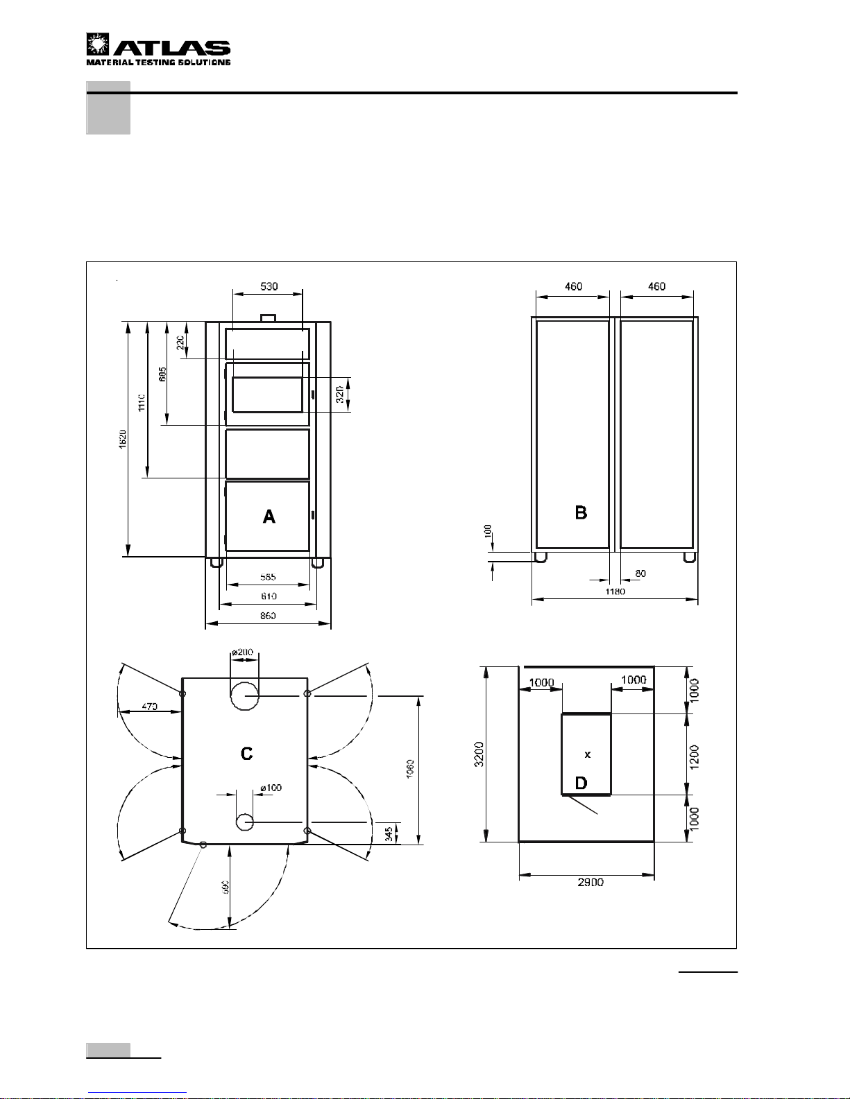
To ensure the accessibility of the instrument for repair, service, and maintenance work, keep
sufficient distances around the instrument open (min 1 m on each side, see Fig. 1):
• Instrument dimensions: 900 x 1200 x 1800 mm (W x D x H)
CAUTION - Instrument overheating!
The air exchange of the instrument is achieved
via air inlet and air outlet openings at the
instrument top and at the side vent openings.
If the air exchange is blocked, the constant conduction of tests will be impaired because the
safety devices will shut the instrument off. Also,
the repeated shut-on/shut-off resulting thereof
will shorten the life of the involved instrument
components.
Make sure that the vent openings are always
clear!
• The operating room must have a minimal
height of 2.5 m.
• Observe the minimal side distances. For the
dimensions of the safety and service
distances, please refer to Fig. 1.
Page 14
14
Operating instructions XENOTEST BETA+
3. Location requirements
3.6 Dimensions of the instrument and space requirements
A Front view
B Side view
C Top view
D Service area space requirements
Fig. 1
All dimensions in mm
Page 15

15
Operating instructions XENOTEST BETA+
4. Description of the instrument
4.1 Front and right view
Fig. 2: Front view:
1 Communication ports
2 Operating panel with touch screen
3 Test chamber door with viewport
4 Test chamber with sample holder turntable
5 Irradiator unit with filter system
6 Access panel for water supply system
7 Container for treated water
8 Height-adjustable stand
9 Lock for water supply system access panel
A Air inlet opening for irradiator cooler and
cooling system for electrical components with
filter in door (see Technical Data)
Right view:
B Side door of electrical supply unit
C Side door of electrical supply unit / humidifi-
cation system
D Test chamber ventilation exhaust air sleeve
E Printer for test documentation
F Main power switch for switching the device
on / off
G Test chamber door release
Fig. 2
Page 16
16
Operating instructions XENOTEST BETA+
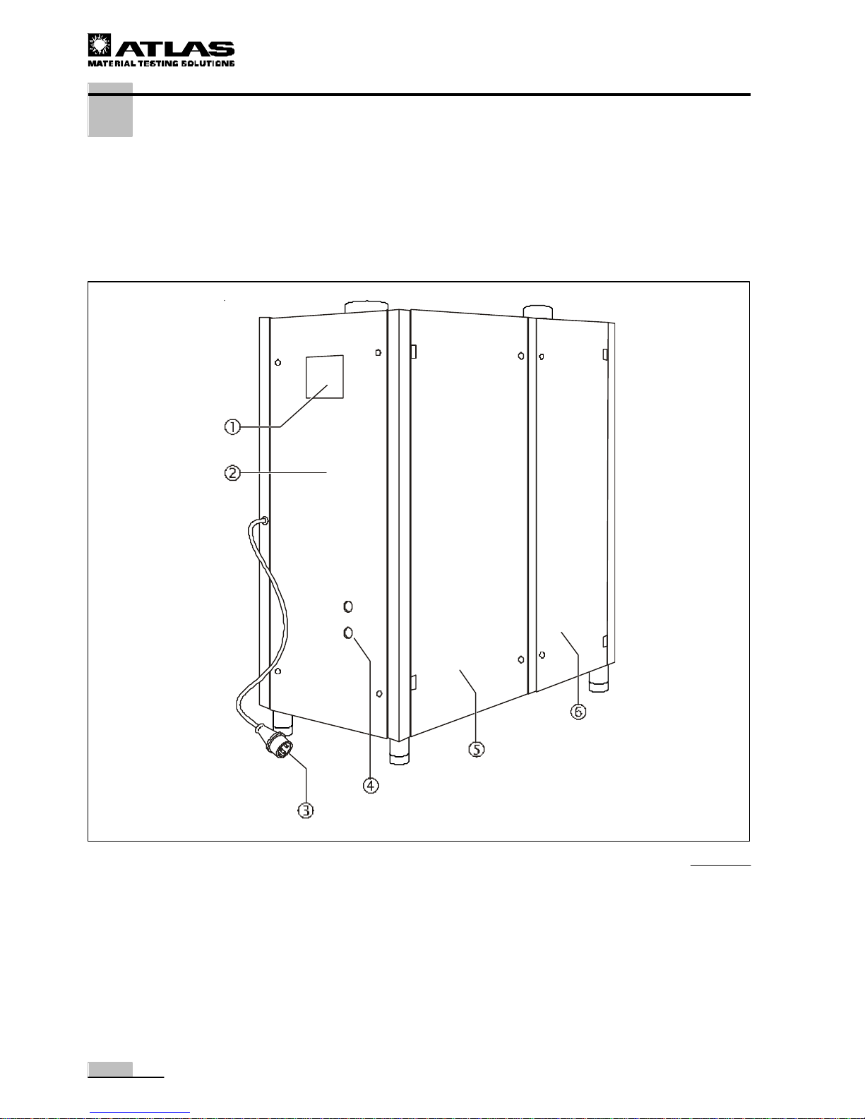
Left view:
5 Side door of electrical supply unit / humidifi-
cation system
6 Side door of electrical supply unit
Fig. 3
4. Description of the instrument
4.2 Rear and left view
Fig. 3: Rear view:
1 Air inlet opening of test chamber cooling
2 Device backpanel cover
3 Connecting cable for device power supply
4 Water connection
Page 17
17
Operating instructions XENOTEST BETA+
4. Description of the instrument
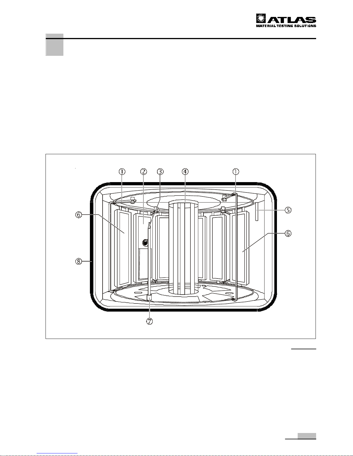
4.3 View of the test chamber
Fig. 4: View of the chamber:
1 Sample holder mount with sample cage strap
(4) for accommodating the sample holder
2 XENOSENSIV sensor for measuring the
irradiation intensity and black standard temperature.
3 Spraye rod for spraying the samples
4 Filter system for generating specific light and
internally installed Xenon irradiators for
irradiating the material samples
5 Integral sensor system for measuring temp-
erature and relative humidity in the test chamber
6 Sample holder for accommodating the samples
7 Spray rod release
8 Door seal
Fig. 4
Page 18
18
Operating instructions XENOTEST BETA+
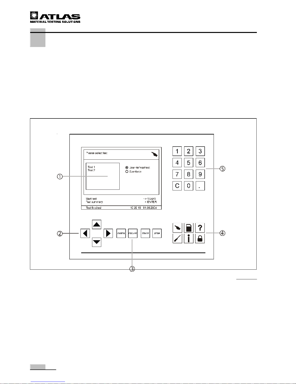
4 Menu keys for activating the program modules
5 Numeric keypad for entering program parame-
ters and test values
Fig. 5
4. Description of the device
4.4 View of the operating panel
Operating panel with touch screen, Fig. 5:
1 Display for menu dialogs, status indicators, and
program parameters
2 Arrow keys for navigation through menus
3 Function keys for selecting basic functions:
• ENTER: For confirming entered values
• ESCAPE : For cancelling menu dialogs
• START: For starting test programs
• STOP: For interrupting tests
Page 19

19
Operating instructions XENOTEST BETA+
5. Functional description
5.1 Program control
Fig. 6: The XENOTEST BETA+ is switched on using the main
switch 2 and operated using the program control 1 of the touch
screen.
The microprocessor-controlled program includes preprogrammed
test sequences as well as the design and initialization of userspecific tests.
The values required for the tests are entered using the numeric
keypad and the various function keys.
The entered data and the resulting status messages are shown
on the display.
The test documentation can be output using an integral (optional) printer 3 on paper rolls.
For details about the program control and about programming
test sequences, refer to the software documentation of the
device.
5.2 XENOCHROME filter system
Fig. 7: The XENOCHROME filter system consists of:
• a filter dome 2 with three absorbers 1 offset by 120°,
• the XENOCHROME filter plates 3 with specific filtration
characteristics:
• XENOCHROME 300 (II) and
• XENOCHROME 320 (III) and
• an exterior cylinder 4
The labeling of the XENOCHROME filters is located at the lower
end of the filters:
For differentiation reasons, the filters are marked with the
character combinations II or 30 and III or 32, respectively.
Fig. 6
Fig. 7
Page 20

20
Operating instructions XENOTEST BETA+
5. Functional description
Representation of the irradiation path:
Fig. 8: The Xenon irradiators 3 irradiate evenly in all directions.
The fractions of the UV und irradiation that strike the coated XENOCHROME filters 2
pass the outer cylinder and irradiate the samples 4 .
The IR irradiation fractions are partially reflected, directed to the black absorbers 1 ,
absorbed by them, and routed to the outside by the cooling air flow.
The irradiation intensity is set in accordance with the filter system in the wavelength range
of 300 to 400 nm used.
• XENOCHROME 300: 45 to 120 W/m²
• XENOCHROME 320: 35 to 100 W/m²
Fig. 8
Page 21

21
Operating instructions XENOTEST BETA+
5. Functional description
Fig. 9: The diagram shows the spectral energy distribution in the wavelength range of
200 - 800 nm using the combination XENOCHROME filter system 300 with outer cylinder. The data in Table 1 on Page 22 correspond with CIE No. 85, Table 4.
Fig. 10: The diagram shows the spectral energy distribution in the wavelength range of
200 - 800 nm using the combination XENOCHROME filter system 320 with outer cylinder. The values of the relative spectral distribution are listed in Table 2 on Page 22.
Fig. 9
Fig. 10
0
2
4
6
8
10
12
200 300 400 500 600 700 800 900
Bestrahlungsstärke [W/m² x nm]
Xenochrome 300
CIE 85
CIE Nr. 85, Table 4
Wavelength [nm]
Iradiation intensity [W/m² x nm]
0
2
4
6
8
10
12
200 300 400 500 600 700 800 900
Bestrahlungsstärke [W/m² x nm]
Xenochrome 320
Wavelength [nm]
Iradiation intensity [W/m² x nm]
Page 22

22
Operating instructions XENOTEST BETA+
5. Functional description
Application:
The XENOCHROME filter systems can be used for the following tests:
ISO 11341, ISO 4892-2, ISO 105-B02, and ISO 105-B06
For the relative spectral distribution of the XENOCHROME filter system, please
refer to the Tables 1 and 2.
* The tolerances listed in the tables are in accordance with the mentioned standards.
5.3 Filter system overview
Tab. 3
RSP* RSP*
< 290 nm 0,15 0.15
290 - 320 nm 24654,00 2.6 - 7.9
321 - 360 nm 34,6 28.2 - 38.6
361 - 400 nm 57,8 55.8 - 67.5
290 - 400 nm 100 100
*Relative spectral proportion standardized to 300 - 400 nm
XENOTEST BETA+ filter: XENOCHROME 300
Wavelength
Xenochrome 300
ISO/DIS 4892-2 (A),
ISO/FDIS 11341 (1)
RSP* RSP*
< 300 nm 0,01 0.29
300 - 320 nm 38018,0 0.1 - 2.8
321 - 360 nm 32,6 23.8 - 35.5
361 - 400 nm 66,2 62.4 - 76.2
300 - 400 nm 100 100
*Relative spectral proportion standardized to 300 - 400 nm
XENOTEST BETA+ filter: XENOCHROME 320
Wavelength
Xenochrome 320
ISO/DIS 4892-2 (B),
ISO/FDIS 11341 (2)
Tab. 2
XENOCHROME filter
Exterior cylinder
XENOCHROME 300, 10 pieces (Labeling II or 30) UV special glass filter
XENOCHROME 320, 10 pieces (Labeling III or 32) UV special glass filter
Page 23

23
Operating instructions XENOTEST BETA+
5. Functional description
5.4 Ventilation system
Fig. 11: The XENOTEST BETA+ is air-cooled. The cooling system is supplied with two
different airflows: irradiator cooling D and test chamber cooling 6.
Irradiator cooling:
A blower C aspirates the air D for the irradiator cooling at the air vents 3 at the right
side of the instrument. The air flows along the assembly duct and cool the electronic components. Then, the air is routed through the external cylinder 2 of the irradiator unit and
cools the Xenon irradiators.
The heated air is carried off through the vent at the top of the device 1 and is aspirated by
a technical ventilation in or removed directly out of the laboratory.
Test chamber cooling in fresh air mode:
The air 6 for the test chamber cooling is aspirated by the blower 9 through the air filter
5 at the air inlet opening.
Depending on the present temperature in the test chamberF, the fresh air feed rating is
controlled using the motor-driven doors 3 and 7.
The airflow is routed past the heating system 8 and heated to the required temperature. The humidification system A then mixes the air with humidified air and feeds the mixture
into the test chamber F. The humidification system removes air from the test chamber
through the inlet air pipe B.
The airflow E is distributed evenly around the sample turntable while temperature and
humidity are constantly measured by the integral sensor system 2.
The used air is carried off through the exhaust air opening 4 and is aspirated by a technical
ventilation in or removed directly out of the laboratory.
Test chamber cooling in recirculating air mode:
In the recirculating air mode, the two air doors 3 and 7 are closed so that the airflow
is routed into the closed air recirculation system.
Fig. 11
Page 24

24
Operating instructions XENOTEST BETA+
5. Functional description
5.5 Spray and humidification system
The spray and humidification system of the XENOTEST BETA+
allows samples to be tested under clearly defined climatic
conditions in the test chamber.
• The humidification system controls the relative humidity of
the air within the test chamber. The settable range is
between 10 % and 95 %. The test chamber is humidified by
8 ultrasonic atomizers.
• The spraying system sprays treated water through a sprayrod in cycles onto the samples without pressure.
Fig. 12: The spray and humidification system is fed through an
instrument-integral water reservoir 4.
A float switch 6 monitors the filling level of the water reservoir
and a magnetic switch 5 reports an excessively low filling level
to the program control.
Two pumps are installed in the water reservoir:
• One pump 7 supplies the humidifier 2 with water for air
humidification.
• The other pump 9 supplies the sample backside cooling
E with cooling water trough a separate supply pipe.
Other pumps:
• The spray pump B pumps the water from the reservoir into
the spray rods D that spray water onto the samples.
Water flowing off is fed back through the return pipe A into the
reservoir or into a gravity drain.
The water reservoir can be drained using the drain plug 8 .
NOTE - Fresh water supply
If the samples release particles during a test
with spraying, and if the cleanliness of the
water is an important criterion for the test, the
spray and humidification system can be
connected through the sleeve 3 to an external water circulation system.
The water return is then connected to the drains
(gravity drain).
The instrument-integral water reservoir is
continuously supplied with fresh, treated water
from a water treatment system or from an
external reservoir.
Fig. 12
Page 25

25
Operating instructions XENOTEST BETA+
5. Functional description
5.6 Measuring and control of sensor system
A combined test chamber temperature/humidity sensor is installed in the test chamber of
the XENOTEST BETA+. This sensor is used to default and constantly control the chamber
temperature and humidity.
The XENOSENSIV sensor can be installed as an option. This sensor moves synchroneously with the samples and captures the measured values of the black standard temperature at sample level (within a temperature range of 0 °C to 130 °C) as well as the
measured values of the irradiation intensity within a wavelength range of 300 nm to 400 nm.
The program control uses the measured values to control the preset parameter values.
Integral sensor system, Fig. 13:
The sensor system 2 installed in the test chamber measures:
• the chamber air temperature and
• the relative humidity.
This measuring system supports the following functions:
• Display of the measured chamber air temperature on the touch screen of the control.
• Constant control of the chamber air temperature according to default values up to 80 °C max.
• Control in accordance with relative electric irradiator rating (0 or 53 to 120 %). 100 %
irradiator rating corresponds with a nominal rating of 2200 VA. The control range 100
to 120 % indicates irradiator aging.
• Display of the measured relative humidity in the test chamber on the touch screen of
the control.
• Constant control of the relative humidity in the test chamber according to default values
up to 95 % r. h. max.
Fig. 13
Page 26

26
Operating instructions XENOTEST BETA+
5. Functional description
Fig. 13: XENOSENSIV sensor:
The optional system supports the following functions:
• Display of the measured irradiation intensity on the touch screen of the control.
• Constant control of the irradiation intensity in the wavelength range of 300-400 nm
(depending on filter system used); XENOCHROME 300: 45 to 120 W/m²,
XENOCHROME 320: 35 to 100 W/m²
• Display of the black standard temperature on the touch screen of the control.
• Constant control of the black standard temperature according to default values up to
130 °C max.
NOTE - Operation without sensor
If the XENOTEST BETA+ is operated without
XENOSENSIV sensor, the irradiation rating is
controlled constantly according to a default
value (see Section 7.2).
In this mode, the adapter for operation without
a sensor (terminating plug) must be connected
to the connecting sleeve (see Section 6.6).
5.7 Calibration sensor system
The calibration and subsequent adjustment of the irradiation intensity and of the black
standard temperature of the XENOSENSIV sensor can be performed using two instrumentindependent sensors:
• the XenoCal BB 300-400 sensor for the irradiation intensity and
• the XenoCal BST Sensor for the black standard temperature
(see Section 7.5).
Page 27

27
Operating instructions XENOTEST BETA+
6. Start-up
6.1 Initial start-up
NOTE - Initial start-up
The initial start-up must be performed only by
an ATLAS Technical Service rep or by an
authorized service company.
During the initial start-up, all functional units of
the instrument are checked for their correct
functions and operability.
The instrument is commissioned in an operational state; the commissioning is documented
in the commissioning log at the end of these
instructions.
6.2 Checking the instrument components
WARNING - Electric shock!
Contact with current-carrying components may
cause a lethal electric shock.
Before checking the instrument components,
disconnect the instrument from the power
supply system!
• Switch the instrument off using the ON/OFF
switch.
• Disconnect the mains plug from the socket
and protect it from accidental reconnection.
• Check to see if the instrument is de-energized.
Only instrument components that are in perfect condition ensure the operational safety of
the XENOTEST BETA+.
Prior to any start-up or test run, check components and their functional units listed below
for possible damage and operability.
Do not use damaged or worn components.
Checklist:
The following functional units must be checked prior to any start-up.
• Correct combination of light filters.
CAUTION - Overheating!
Apart from the light filtering, the light filters are
also used for absorbing heat. If tests are conducted without light filters, the instrument may
overheat and the samples may be damaged.
Ignite the Xenon irradiators only when light
filters are employed.
• Number of Xenon lamp operating hours.
• Condition of the air filters for irradiator cooling and test chamber cooling.
• Connection and possible leakage of water hoses.
• Condition of the water filter.
Page 28

28
Operating instructions XENOTEST BETA+
6. Start-up
• Filling level of the instrument-integral water reservoir or of the supply reservoir for treated
water.
• Condition of connector and power supply cable.
• Installation of the terminating plug for the XENOSENSIV sensor.
NOTE - Operation without sensor
If the XENOTEST BETA+ is operated without
XENOSENSIV sensor, the adapter for operation without sensor (terminating plug) must be
connected to the connecting sleeve (see Section
6.6).
Page 29

29
Operating instructions XENOTEST BETA+
6. Start-up
6.3 Installing / Removing Xenon lamps
WARNING - Electric shock!
Contact with current-carrying components may
cause a lethal electric shock. The irradiator
ignition system is under high voltage. Prior to
removing / installing the Xenon lamps, disconnect the instrument from the power supply
system!
• Switch the device off using the ON/OFF
switch.
• Disconnect the mains plug from the socket
and protect it from accidental reconnection.
• Check to see if the device is de-energized.
CAUTION - Risk of burns!
The components of the irradiation unit reach
extremely high temperatures; contact with skin
may cause burns.
Prior to replacing the Xenon lamp, allow the
irradiation unit components to cool down
sufficiently!
NOTE - Handling the Xenon lamp:
Residues from finger contact may burn into the
Xenon lamp glass tube and cause uneven irradiation.
• Grasp the Xenon lamp only at the lamp
socket.
• Wear clean cotton gloves for installation.
Removing the Xenon lamp:
1. Fig. 14: Remove the exhaust air hose (or air duct adapter). Remove the adapter from the exhaust air duct or from
the technical ventilation.
2. Release the exhaust air lid with connecting sleeve 4 and
fold it upward.
3. Remove the intermediate tube 5 from the flange 6 and put
it aside. The ground conductor cable connects the intermediate tube to the flange tube.
4. Remove the lamp contact sleeves 1, 2 and 3.
5. Remove the lamp centering piece 8.
6. Cautiously pull the old Xenon lamp 7 up out of the lamp
socket.
Fig. 14
Page 30

30
Operating instructions XENOTEST BETA+
6. Start-up
NOTE - Handling lamps and filter plate s
Residues from finger contact may burn in and
cause uneven irradiation.
• Wear clean cotton gloves for installation.
Installing the Xenon lamp:
1. Fig. 15: Insert the Xenon lamps 7 through the flange 6 into
the lamp socket and push it in carefully all the way to the
stop.
2. Place the lamp centering piece 8 between the Xenon
lamps.
3. Install the contact sleeves 1, 2 and 3 to the lamps. Make
sure that the contact sleeves are connected to the pertaining
lamps:
Lamp 1 = left (cable no. 26),
Lamp 2 = center (cable no. 27),
Lamp 3 = right (cable no. 28).
4. Place the intermediate tube 5 onto the flange 6. Make sure
that the ground conductor cable is secured with screws to
the flange and that the lamp connector cables are located
in the recesses.
5. Close the exhaust air lid with connecting sleeve 4 and latch
it.
6. Reinstall the adapter to the exhaust air duct or to the technical ventilation.
CAUTION - Overheating!
Apart from the light filtering, the light filters are
also used for absorbing heat. If tests are
conducted without light filters, the instrument
may overheat and the samples may be
damaged.
Ignite the Xenon irradiators only when light
filters are employed.
NOTE - Irradiator ignition
When the exhaust air lid at the top of the instru-
ment is opened, the irradiation system is
switched off. After the lid has been closed, the
system must be ignited again to resume the
irradiation process.
Fig. 15
Page 31

31
Operating instructions XENOTEST BETA+
6. Start-up
6.4 Replacing the filter system
XENOCHROME filter system:
The XENOCHROME filter system (300/320) consists of 10 filter
plates. The XENOCHROME filter dome is required for accommodating the filter plates.
Loading the filter dome:
1. Fig. 16: Clean the filter plates 1 using soft cloths and
commercial alcohol or spirit.
2. Insert the filter plates 1 from above into the slot 3 of the
XENOCHROME filter dome 2 .
3. Push the filter plates in the mount all the way to the stop.
Table 4 shows an overview of available filter types and their
labeling.
Fig. 17: Installing / Removing the filter dome:
The filter dome is inserted from above into the outer cylinder
and rotated into position
1. Remove the Xenon lamp system (see Section 6.3).
2. Remove the filter dome 1 from the external cylinder 6.
3. Insert the filter dome 1 into the external cylinder 6 and
align the distances between the absorbers and the lamps
evenly.
4. Install the Xenon lamp system (see Section 6.3).
Installing / Removing the external cylinder:
Removal
1. Remove the Xenon lamp system (see Section 6.3).
2. Fig. 17: Remove the filter dome 1 from the external
cylinder 6.
3. Remove the four retaining screws 2 from the flange 3.
4. Open the test chamber door and push the tube sleeve of the
removed flange slightly up from inside.
5. Remove the external cylinder 6 .
Installation
6. Fig. 17: Insert the lower sealing ring 5 into the guide groove
and install the exterior cylinder 6 from the front through the
test chamber door
7. Insert the upper sealing ring 4 into the tube sleeve and
place the sleeve onto the exterior cylinder.
8. Secure the flange 3 using the screws while observing the
centering of the exterior cylinder.
9. Insert the filter dome 1 into the exterior cylinder.
10. Install the Xenon lamp system (see Section 6.3).
Fig. 16
Fig. 17
Filter type
Filter plates Labeling
XENOCHROME 300 10 II or 30
XENOCHROME 320 10 III or 32
Tab. 4
Page 32

32
Operating instructions XENOTEST BETA+
Fig. 18
Fig. 19
6. Start-up
6.5 Loading sample holders
The sample holders are not included in the standard equipment
of the instrument. Sample holders can be ordered through the
ATLAS MTT GmbH.
NOTE - Loading the sample turntable
To ensure reproducable test conditions, all of
the 11 sample holders must be installed to the
sample turntable.
Unused sample holders are loaded with sample blanks.
Standard sample holders:
Fig. 18: The standard sample holder set (Part No. 56076543)
consists of 16 sample holders with the dimensions 320 mm x
80 mm x 10 mm (H x W x D).
A standard sample holder 5 (Part No. 56052571) can accommodate samples with a thickness of 10 mm max.
Cover sheets:
For the standard sample holder, three different cover sheets are
available with exposure areas of different sizes. Cover sheets are
used for the direct optical comparison between exposed and
unexposed sample areas.
1 Cover sheet, 27 mm (Part No. 56050992)
2 Cover sheet, 18 mm (Part No. 56050990)
3 Cover sheet, 9 mm (Part No. 56050988)
Sample holder board:
Fig. 18: ISO Standard 105-B02 contains details about backing
up the sample bodies on a cardboard.
For this purpose, sample holder boards 4 with the dimensions
320 mm x 80 mm x 0.05 mm (Part No. 56076547) are available.
NOTE - Surface temperature
The boards can affect the surface temperatures
of the samples.
The sample holder board is placed between the sample and the
sample holder.
Loading standard sample holders:
1. Fig. 19: Place the sample 2 into the sample holder 5.
2. Place the cover sheet 1 onto the sample and secure it
using the clamps 4.
3. Place the standard sample holder in the sample chamber to
the lower sample holder strap using the retainer 3 and to
the upper sample holder strap using the two retainers 6.
Page 33

33
Operating instructions XENOTEST BETA+
6. Start-up
Special 3-piece sample holder:
To differentiate test series with large sample quantities even
further, special sample holders with divided sightgwindows (Part
No. 56076699) can be used that allow three samples to be
placed in one sample holder.
1. Fig. 20: Place the individual samples 2 into the sightwindows of the sample holder 5.
2. Place the cover sheet 1 onto the samples and secure them
using the clamps 4.
3. Place the special sample holder in the test chamber to the
lower sample holder strap using the retainer 3 and to the
upper sample holder strap using the two retainers 6.
Special 2-piece sample holder:
The 2-piece sample holder (Part No. 56076760) is suitable e.g.
for lightfastness tests.
1. Fig. 21: Insert the samples 2 into the two sightwindows
of the sample holder 6; if required, place some material 3
under the samples to back them up.
2. Place the cover sheet 1 onto the samples and secure them
using the clamps 5.
3. Place the special sample holder in the test chamber to the
lower sample holder strap using the retainer 4 and to the
upper sample holder strap using the two retainers 7.
NOTE - Surface temperature:
The materials used for backing up the samples
may affect the surface temperature of the
samples.
Loading sample holders for sample backside cooling:
Fig. 19: For weathering processes under corrosive conditions,
dewing of the samples may be required to generate a condensate coating on the sample surface.
In this case, the dew point lower deviation is simulated in the
check routine after the transition from an irradiation phase into
a dark phase by spraying the backsides of the samples with
water.
To achieve effective sample cooling, the samples are placed onto
sample holders with open backpanels 7.
Housing for bluescales:
For weathering tests, e.g. in accordance with ISO 105-B04, a
special housing is available that accommodates the bluescale and protects it from direct spraying (see Section 12,
Accessories).
Fig. 21
Fig. 20
Page 34

34
Operating instructions XENOTEST BETA+
6. Start-up
6.6 Installing the XENOSENSIV sensor
CAUTION - Risk of burns!
The test chamber is extremely heated during
operation. Contact with heated test chamber
components may cause burns. Prior to any
sensor installation or removal, allow the test
chamber to cool down sufficiently!
1. Fig. 22: Install the XENOSENSIV sensor 2 using the two
retaining screws 4 to the adapter 3 of the sensor mounting
bracket 1.
2. For installation, the sensor mounting bracket 1 is positioned to the left or right sample holder straps next to the
connecting sleeve 6 .
3. Connect the connector 5 of the connecting cable to the
sensor receptacle 6.
NOTE - Operation without sensor
If the XENOTEST BETA+ is operated without
XENOSENSIV sensor, the adapter 7 for operation without sensor (terminating plug) must
be connected to the connecting sleeve 6 .
Fig. 22
Page 35

35
Operating instructions XENOTEST BETA+
6. Start-up
6.7 Filling the water reservoir
Fig. 23: Manual filling of the water reservoir:
1. Open the lower door 2 at the front of the instrument.
2. Lift the lid 1 of the water reservoir 3 open. Fill the reservoir with approx. 40 l of treated
water (specifications for treated water see Section 3.4).
3. Close the water reservoir lid, then close the instrument door.
Connection to an external water recirculation system:
1. Connect the water supply hose to the sleeve (at the rear
of the water reservoir).
2. Check the water reservoir filling level.
Fig. 23
Page 36

36
Operating instructions XENOTEST BETA+
6. Start-up
6.8 Connecting the irradiator cooling to the
exhaust air system
NOTE - Irradiator cooling exhaust air
The irradiator cooling of the XENOTEST BETA+
must be connected to an exhaust air system.
If the maximum length of the exhaust air duct
and the permitted number of 90° elbows (max.
2) are exceeded, the instrument exhaust air
system may overheat. In this case, the safety
devices of the XENOTEST BETA+ will interrupt
the power supply permanently.
Please observe the specifications for the instrument exhaust air system in Section 3.3.
Connecting the exhaust air system:
1. Fig. 24: Place the adapter 1 of the on-site exhaust air
system onto the connecting sleeve 2 at the XENOTEST
BETA+. The connecting sleeve has a diameter of 100 mm.
2. Check to see if the exhaust air system has an open outlet
into the open or if the on-site technical ventilation system is
operational.
CAUTION - Harmful UV radiation!
If no connection between the instrument and
the on-site exhaust air system is installed, UV
radiation may escape.
UV radiation may irritate the retina and the
surface of the skin.
Operate the instrument only if the exhaust air
system is operational.
Fig. 24
Page 37

37
Operating instructions XENOTEST BETA+
6. Start-up
6.9 Setting up the interface
Fig. 25: The instrument is equipped with four interfaces for data
communication with external systems.
Network connection 1:
Via the protocol "Integrated Fast Ethernet Controller" (3C905CTX-compatible), the test instrument can be integrated into a
network. Available only with later software version.
Serial interface 2 :
The RS232 interface allows the output of measuring data to
a computer during a running test program.
USB interface 3 :
Data interface in accordance with USB 2 standard. This interface
allows the output of measuring data to a computer during a
running test program. Available only with later software
version.
Slot 4 for SmartMedia chip 5:
For updating already installed instrument software, loading new
check programs or downloading measuring and test data.
6.10 Power supply connection
WARNING - Electric shock!
Contact with current-carrying components may
cause a lethal electric shock.
Prior to connecting the instrument to the power
supply system, check plug and power supply
cable.
Do not use damaged components for a connection to the power supply system!
The XENOTEST BETA+ is connected to a mains voltage of 400
V ± 10 %
The power supply connection is made through a grounding plug
(3P,N,PE), CEE (32 A, 5 poles, 6h).
The power supply system must be properly fused.
Connecting and switching the instrument on:
1. Prior to connecting the instrument to the power supply
system, check to see if the specifications of the power
supply system in the operating rooms corresponds with the
ratings on the nameplate at the rear of the instrument.
2. If the ratings for voltage (V) and maximum current (A) do not
correspond with the technical data (see Section 11), the
instrument must not be connected.
3. Fig. 26: Connect the grounding plug 2 (at the rear of the
instrument) to a properly grounded and fused outlet.
4. Make sure that the power supply cable is not subject to
pressure or tensile forces.
5. Fig. 26: Move the main switch 1 to position "I".
Fig. 25
Fig. 26
Page 38

38
Operating instructions XENOTEST BETA+
6. Start-up
6.11 Setting up the printer
You can use the printer to print data of the stored program as well
as the current measuring values of the running program on paper
rolls.
Operating and display elements, Fig. 27:
1 LED: indicates that the paper roll is empty.
2 LINE FEED/ENTER: Dual-function key.
In print mode, the LINE FEED key is used for manual paper
feed. If the menu program is open, it is used as the ENTER
key for accepting and storing the selected parameters.
3 Front panel latch: The front panel can be opened for
inserting the paper roll.
4 LINE MENU/SELECT: Dual-function key.
If the key is depressed for more than 3 seconds with the
XENOTEST BETA+ switched on, the printer switches to
menu program mode. In this mode, the printer parameters
can be changed.
If the menu program is open, the Select key is used for
selecting the various device parameters.
5 Tear-off edge: For tearing the paper strip off.
Inserting a paper roll:
1. Cut the front end of the roll to form a pinted angle.
2. Press the latch to the right and open the printer front
panel.
3. Fig. 28: Insert the paper roll 1 so that it unwinds in a
clockwise direction and lead the paper to the feed duct 2.
4. Slide the paper into the guide slot 2.
5. Keep the LINE FEED/ENTER key depressed until the front
end of the paper appears at the tear-off edge.
Fig. 27
Fig. 28
Page 39

39
Operating instructions XENOTEST BETA+
6. Start-up
Printer settings:
The printer is set at the factory to the following parameters:
Printer Interval NO
Printer Address 00--Print Always
Data Format 8 NO Parity
Baud Rate 2400
Interface Serial
Character Set National Language
Characters/line 40
Print Format Normal
Print Strength a.....+.....a
Mode Online
Changing the printer parameters:
The factory settings can be changed according to customer-specific requirements.
1. Open the parameter menu,
Keep the MENU/SELECT key at the printer depressed for approx 3 seconds.
The control touch screen shows the following message:
ACTUAL PARAMETER?
PRESS ENTER
2. To print a list of the actual parameters,
press the LINE FEED/ENTER key at the printer.
The operating panel display shows the following message:
CHANGE OF PARAMETERS?
3. To change the parameters, keep the LINE FEED/ENTER and MENU/SELECT keys at
the printer simultaneously depressed for approx. 4 seconds.
The operating panel display shows a list of the parameters.
4. To change a value, press the MENU/SELECT key.
Enter the value and confirm it by pressing the MENU/SELECT key.
You can use the arrow keys at the operating panel to move between parameter
lines.
5. To exit the parameter menu
keep the LINE FEED/ENTER and MENU/SELECT keys at the printer simultaneously
depressed.
If the parameter menu is not exited manually, the control program cancels the
parameter menu automatically after 3 minutes.
Page 40

40
Operating instructions XENOTEST BETA+
Fig. 29
7. Operation
7.1 Menu structure of the instrument control
Fig. 29: Overview of the menu structure of the program modules and of the pertaining submenus.
Page 41

41
Operating instructions XENOTEST BETA+
7. Operation
7.2 Operating the touch screen
Functional units:
Fig. 30: The instrument control via touch screen is achieved either
with a finger or with a touchpen USING three functional units:
3 Function keys for activating the basic functions with arrow
keys 2 for navigation through the menus.
4 Menu keys for activating the program modules and the
pertaining submenus.
5 Numeric keypad for entering program parameters.
Program module:
The instrument is controlled with 6 program modules that can be
accessed via the menu keys. Each program module is represented in the pertaining dialog window by an icon 3. The icons
have the following meanings:
h Enter tests / Change
e Output data
? Help
p Change settings
i Display data
k User profiles
The program modules can be accessed anytime; the icon
symbol in the display and a frame in the corresponding symbol
color indicate which menu key has been activated C.
User guiding:
The user menus are generally self-explaining. Each dialog
window contains notes about possible user actions or working
steps and displays information about the status of an initiated
action as well as general, primary information:
5 Request for user action
B Note about next possible, executable working steps
6 Status bar with display:
• Text information 7: Test running / interrupted /
completed
• Progress indicator 8 (during a running test)
9 Time
A Date
Fig. 30
Page 42

42
Operating instructions XENOTEST BETA+
7. Operation
Basic functions:
Fig. 31: Function keys for controlling basic functions:
b Confirm input
m Cancel action or return to the previously
selected menu
t Start program
n Interrupt program
The arrow keys 1 are used for highlighting an item in a selection
list.
o Move the highlight up
u Move the highlight down
l Move the highlight left
r Move the highlight right
Functions of the screen keyboard:
3 First letter uppercase, all others lowercase (Ab).
Must be reactived after a blank has been set.
4 All letters uppercase (AB).
5 Deletes all letters to the right of the cursor.
6 Deletes all letters to the left of the cursor.
7.3 Switching the instrument on
Fig. 32: When the instrument is switched on using the main
power switch, the software control is initialized. The boot process
is indicated by a start image, then the test selection dialog window
appears.
Fig. 31
Fig. 32
Page 43

43
Operating instructions XENOTEST BETA+
7. Operation
7.4 Starting the test program
The program control of the XENOTEST BETA+ allows access to:
• OWN TEST - user specific test programs - The following test
conditions can be defined:
• phases of light or dark,
• controlled irradiation intensity,
• controlled black standard temperature,
• controlled sample chamber temperature,
• controlled humidity,
• cyclic spraying or dewing of the samples.
• Standards - pre-programmed tests that conform to
international standards.
Selecting and starting a test program, Fig. 33:
1. After switch-on, the display 1 shows the test input
dialog window.
2. Set the configuration type 5 for the test. Specify whether
user specific or pre-programmed tests by Atlas are to be
used (Own tests / Standards).
3. Highlight the test program 4: Use the UP / DOWN arrow
keys 2 to select the test program.
4. To start the test program:
Press the t key
5. To interrupt the program run:
Press the nkey
6. To display a test overview:
Press the LEFT / RIGHT arrow keys 2
NOTE - Software documentation
The operation of the instrument control and
the programming of the test programs is
described in the separate software documentation.
Abb. 33
Page 44

44
Operating instructions XENOTEST BETA+
7. Operation
7.5 Adjusting the XENOSENSIV sensor
To ensure reproducable test conditions, the XENOSENSIV sensor can be adjusted using
two instrument-independent sensors:
• XenoCal BB 300-400 sensor (Part No. 55007863) for adjusting the irradiation inensity
within a range of 300 to 400 nm.
• XenoCal BST sensor (Part No. 55007861) for calibrating the black standard temperature
Based on this measuring data, the irradiation intensity and the black standard temperature
can be adjusted (see BELOW).
NOTE - Access privilege
The adjustment menu can be accessed only by
logged-on users.
Identifying a new XenoSensiv sensor:
If a new Xeno Sensiv sensor is entered as a control unit into the instrument control, all
existing adjustment data for irradiation intensity and black standard temperature is deleted.
1. Press the NEW XENOSENSIV switch.
2. Enter the serial number into the input field
.
3. Save the settings:
Press the bkey
4. Confirm the safety request:
The existing data for irradiation intensity and black standard temperature is deleted.
Adjusting the irradiation intensity:
1. Interrupt the test:
Press the nkey
2. Insert the operational XenoCal BB 300-400 sensor instead of a sample holder into
the sample holder rack.
3. Resume the test (without spray, dark phase or sample backside cooling):
Press the tkey
4. After approx 30 minutes (the run time should be at least 15 minutes), interrupt the
test.
Press the nkey
Page 45

45
Operating instructions XENOTEST BETA+
7. Operation
5. Remove the XenoCal BB 300-400 sensor from the test chamber and read the value of
the measured irradiation intensity.
6. Select the Settings program module:
Press the pkey
7. Select the following program functions in succession:
• Press the Adjustment switch,
• Press the Adjustment E switch.
8. Enter the irradiation intensity value read with the XenoCal BB 300-400 sensor into
the input field. The display now shows the old adjustment factor and the newly
calculated adjustment factor.
If the new factor is not within the tolerance (below 0.8 or above 1.2), send the
XENOSENSIV sensor in to ATLAS for a check.
9. Confirm the new adjustment factor:
Press the bkey
After an adjustment has been made, the adjusted test parameters should be calibrated
(measured value check).
Adjusting the black standard temperature:
1. Interrupt the test:
Press thenkey
2. Insert the operational XenoCal BST black standard temperature sensor instead of
a sample holder into the sample holder rack.
3. Resume the test (without spraying, dark phase or sample backside cooling):
Press the tkey
4. After approx 45 minutes (the run time should be at least 45 minutes), interrupt the test.
Press thenkey
5. Remove the XenoCal BST sensor from the test chamber and read the value of the
measured temperature.
6. Select the Settings menu:
Press the pkey
7. Select the following program functions in succession:
• Press the Adjustment switch,
• Press the Adjustment BST switch.
Page 46

46
Operating instructions XENOTEST BETA+
7. Operation
8. Enter the black standard temperature value read with the
XenoCal BST sensor into the input field. The display now
shows the old adjustment factor and the newly calculated
adjustment factor.
If the new factor is not within the tolerance (below 0.8 or
above 1.2), send the XENOSENSIV sensor in to ATLAS
for a check.
9. Confirm the new adjustment factor:
Press the bkey
After an adjustment has been made, the adjusted test parameters should be calibrated
(measured value check).
7.6 Control without senors
Controlling the irradiation intensity without XENOSENSIV sensor:
If the device is operated without the XENOSENSIV sensor, the control is perfomed in
accordance with the relative rating of the Xenon lamp within a range of 53 to 120 %.
100 % lamp rating correspond with the nominal rating of 2200 VA.
The control range of 100 to 120 % considers lamp aging.
NOTE - Operation without sensor
If the XENOTEST BETA+ is operated without
XENOSENSIV sensor, the adapter for operation without sensor (terminating plug) must be
connected to the connecting sleeve (see section
6.6).
Page 47

47
Operating instructions XENOTEST BETA+
7. Operation
7.7 Temperature fields
The black standard temperature (BST) and the chamber air temperatur (CHT) or the difference
between the two: ∆T = BST-CHT is of utmost importance for the material testing.
The two diagrams show the temperature fields ∆T for the various filter systems in dependence of the irradiation intensity.
The black standard temperature is controlled through the blower fan speed in dependence
of illumination intensity, chamber air temperature, and selected filter system. The settable
blower fan speed range is 800 to 2500 rpm.
At maximum blower speed, minimum ∆T values can be achieved; at minimum blower fan
speed, maximum ∆T values can be achieved.
With the idealized representation of the temperature fields, deviations are possible.
Fig. 34: Temperature fields for use of the XENOCHROME filter systems
For the filter system used, the number of ideally possible instrument settings (E, Delta T)
is given through all the points within the quadrangle.
Fig. 34
0
10
20
30
40
50
60
0 20 40 60 80 100 120 140
EUV (W/m²)
BST-CHT (°C)
XENOCHROME 300
XENOCHROME 320
Blower fan speed 2500
Blower fan speed 800 rpm
Page 48

48
Operating instructions XENOTEST BETA+
7. Operation
7.8 Adjusting the test chamber humidity
The test chamber humidity is set in dependence of test chamber temperature and blower
fan speed.
The settings are made at the operating panel as parameters of a test program (see software
documentation for XENOTEST BETA+).
Fig. 35: The humidity diagram shows the setting range for the relative humidity and the
humidity behavior with rising test chamber temperatures.
The settable blower fan speed range is 800 to 2500 rpm. The lamp rating of 2000 W
corresponds with approx. 81 % of the possible rating.
0
10
20
30
40
50
60
70
80
90
100
10 20 30 40 50 60 70 80 90
Test Chamber Temperature [°C]
Relative Humidity [%]
800
1250
2000
2500
Blower speed
Fig. 35
Page 49

49
Operating instructions XENOTEST BETA+
8. Shut-down
8.1 Switching the instrument off
The instrument can be switched off after completion or interruption
of a test program.
Switching the instrument off after completion of a test program:
• After the instrument has cooled down, move the master
switch to position "0".
Interrupting a test program and switching the instrument
off:
1. To interrupt the program run:
Press thenkey
2. Fig. 36: After the instrument has cooled down, move the
master switch to position "0".
8.2 Switching the instrument off in an
emergency
• Fig. 36: Move the master switch to position "0".
8.3 Removing samples
CAUTION - Risk of burns!
The samples are extremely heated during a test
program run.
Contact with heated samples may cause burns.
To remove samples, wear protective gloves!
To remove samples:
1. Switch the instrument off.
2. Open the test chamber door.
3. Allow the samples to cool down sufficiently.
4. Remove the sample holders from the retainers.
Fig. 36
Page 50

50
Operating instructions XENOTEST BETA+
9. Troubleshooting
9.1 Error messages and correction
Error message Correction
Unable to reach irradiation intensity
setpoint (E).
Maximum permissible program parameter deviation set too small.
Time to error message generation set too short.
Adjust XENOSENSIV sensor as required.
Clean the filters.
Check that the correct filter system is being used.
Check that the correct filter system is programmed.
Check the age of the xenon bulb.
Replace the filters.
Unable to reach black standard
temperature (BST).
Program parameter deviation set too low.
Time to error message generation set too short.
Check blower speed.
Check irradiation intensity.
Check XENOSENSIV sensor with black standard temperature sensor
and adjust as required.
Unable to reach setpoint sample
chamber temperature (SCT).
Black standard temperature set too low.
Time to error message generation set too short.
Invalid program parameters. The following error messages may be displayed after pressing the
START key:
- Program for sensor-free operation
- Program for sensor operation
- Program for other filter system
Correct problem according to the instructions below. If no error
message is displayed, reenter the program.
Program for sensor-free operation. Check that the connecting plug is firmly seated.
Program for sensor operation. Check that the XENOSENSIV sensor is installed.
Xenon bulb too old. Unable to reach
irradiation intensity with current filter
system.
Clean the filters.
Check that the correct filter system is used.
Check that the correct filter system is programmed.
Check the age of the xenon bulb.
Replace the filters.
Check the XENOSENSIV sensor:
Check the selected filter system and irradiation intensity in the test
program.
Program for other filter system.
Water to humidifier colder than 18 °C. Wait until water temperature
rises during operation.
Humidifier output limit reached. Refer to Section 7.4 for humidity limit
chart.
Unnable to reach setpoint humidity.
Maximum permissible black standard temperature set too low.
Check blower speed.
Check irradiation intensity. Check XENOSENSIV sensor and adjust
as required.
Max.black standard temperature
exceeded.
Tab. 5-1
Page 51

51
Operating instructions XENOTEST BETA+
9. Troubleshooting
Tab. 5-2
Error message Correction
Low water level, reservoir Top up reservoir
Sample chamber door open. Close sample chamber door.
Device cover open. Close device cover.
Sample chamber overtemperature. Contact Technical Service
Irradiator exhaust air overtemperature. Contact Technical Service
Series device overload. Contact Technical Service
Sample chamber air recirculation faulty. Contact Technical Service
Sprinkler failure. Contact Technical Service
Humidification failure. Contact Technical Service
Battery missing or discharged. Contact Technical Service
Battery older than 5 years. Contact Technical Service upon next inspection.
Low water level, humidifier. Check the tubing and connections.
Check the filling level in the reservoir.
XENOSENSIV sensor or terminating
plug not installed.
Check that the XENOSENSIV sensor or terminating plug are
installed.
Check the xenon bulb seat.
Check the xenon bulb fuse.
Check the xenon bulb`s age.
Lamp will not ignite.
Contact Technical Service. The device remains operative.
Reenter program, time and filter system.
Memory error
Performing basic inizilisation
--> ENTER
All device data and calibration factors
deleted --> ENTER
Power failure
on dd.mm.yy. at hh:mm
Refer to the software documentation.
Resume interrupted program by inputting the appropriate data.
Page 52

52
Operating instructions XENOTEST BETA+
10. Maintenance
10.1 Inspection
The device must be inspected annually.
The inspection comprises particularly:
• the safety devices
• the function of the program control
NOTE - Warranty
The manufacturer warrants the safety and
correct function only under the condition that:
• the inspection intervals are observed
• all inspections are performed by adequately
trained and qualified personnel or by the
Technical Service of ATLAS MTT GmbH
NOTE - Service package
ATLAS offers an instrument-specific service pa-
ckage that comprises inspections, measuring
service, and calibration service.
10.2 Repairs
Repair work must be performed only by adequately trained and qualified personnel or
by the Technical Service Group of ATLAS MTT GmbH.
Use only original spare parts for installing or replacing instrument components.
ATLAS is not liable for instrument components or spare parts from third-party suppliers.
NOTE - Service documents
A complete spare parts list and other repair
documentation are available to expert
personnel at request.
Page 53

53
Operating instructions XENOTEST BETA+
10. Maintenance
10.3 Service
WARNING - Electric shock!
Contact with current-carrying components may
cause a lethal electric shock. The irradiator
ignition system is under high voltage. Prior to
service work, disconnect the instrument from
the power supply system!
• Switch the instrument off using the ON/OFF
switch.
• Disconnect the mains plug from the socket
and protect it from accidental reconnection.
• Check to see if the device is de-energized.
Fig. 37: Installing / Removing the irradiation cooling air
filter:
1. Open the right device door 1 and rotate the retaining
screws using a screwdriver.
2. Pull the filter 3 out of the mounting 2.
3. Push the new filter into the mounting.
4. Close the instrument door.
Cleaning the air filters:
The air filters for irradiator cooling and test chamber cooling must
be cleaned every six months.
Clean the filter in a solution of tepid water and some light-duty
detergent and rinse it thoroughly.
In case of stubborn dirt, tap the filter mat clean, vacuum it or
blow it out using a soft compressed air stream, then clean it in
water.
Replacing the air cleaners:
After the two filters have been cleaned twice, they must be replaced.
Fig. 38: Installing / Removing the sample chamber cooling
air filter:
1. Pull the filter 1 out of the mounting 2.
2. Insert the new or cleaned filter and secure it in the mounting.
Replacing the Xenon lamp:
To comply with the irradiation consistency, the Xenon lamp must
be replaced after 1500 operating hours (see Section 6.3).
The required replacement after 1500 operating hours is reported
by the program control. The age of the Xenon lamp can also
be requested during a program run using the "DATA" key (see
software documentation).
Fig. 37
Fig. 38
Page 54

54
Operating instructions XENOTEST BETA+
10. Maintenance
Cleaning the water filter:
The dirt filter of the water pump must be cleaned every six
months. In case of stubborn dirt resulting from color slush from
samples that give off particles during a test the air filter must be
replaced.
After the dirt filter has been cleaned twice, it must be replaced.
Fig. 39: Installing / Removing the dirt filter:
The dirt filter 6 is an integral part of the water pump 2. The
water pump is installed in the water reservoir 1 of the device.
1. Switch the device off using the main switch, disconnect the
power plug from the mains socket and protect it from
accidental reconnection.
2. Disconnect the water hose from the connecting sleeve 3.
3. The water pump is attached to the floor of the water
reservoir with suction cups 5 . Pull the water pump off the
floor.
4. The protective grid 4 is attached to the pump housing. Pull
the grid off.
5. Remove the water filter 6 from the protective grid 4 and
rinse it thoroughly in tepid water.
6. Reinsert the water filter into the protective grid and attach
the grid to the pump housing.
7. Place the water pump onto the floor of the water reservoir
and push it on slightly so that the suction cups secure the
pump.
Fig. 39
Page 55

55
Operating instructions XENOTEST BETA+
10. Maintenance
10.4 Cleaning
Fig. 40: Cleaning the water reservoir:
To protect the piping system and the test chamber from dirt, the
water reservoir should be emptied before each new test program
and rinsed with clear water.
1. Open the left instrument door and rotate the retaining screws
using a screwdriver.
2. Connect the coupling 1 of the water reservoir drain hose
2. The drain hose is located at the left side of the device
at the water reservoir.
3. Empty the water reservoir using the drain hose.
4. Disconnect the drain hose from the connecting sleeve.
5. Open the lower instrument door at the front side.
6. Remove the water reservoir.
7. Dry the reservoir using a clean cloth.
Cleaning filters and glass components:
Clean the UV special-glass exterior cylinder and the window
filters using a 20 % solution of citric acid, then rinse with
water.
Wipe the XENOCROME filter set clean using a clean cloth that
has been dampened with commercial alcohol or spirit.
NOTE - Handling filter plates
Residues from finger contact may burn into the
filter plates and cause uneven irradiation.
• Wear clean cotton gloves for cleaning filter
and glass components.
Cleaning the test chamber:
Clean the test chamber using liquid stainless-steel cleaners
without chlorine compounds.
Rinse with pure water to prevent cleaning agent residues from
entering the water recirculation system.
Cleaning the instrument surface:
CAUTION - Plastic surfaces!
Parts of the instrument surface are made of
plastic material. Solvents may attack plastics
and make them unusable.
Do not clean the instrument surface and particularly the operating panel using solvents that
contain hydrocarbon.
Clean the instrument surface using a solution of tepid water and
commercial dishwashing agent, wipe the surface clean and dry
it using a clean cloth.
Fig. 40
Page 56

56
Operating instructions XENOTEST BETA+
11. Technical data
Power supply:
Mains connection: (3P, N, PE) AC, CEE (32A, 5 poles, 6h)
Nominal voltage / frequency: 400 V ±10 %, 50/60 Hz
Nominal current: 16 A
Nominal output: approx 12 kVA max
Xenon lamp nominal rating: 2200 VA
Xenon lamp rating: 2780 VA max
Xenon lamp current: 20 A max
Relative elecrical rating: 53 - 120 %
(without XENOSENSIV sensor)
Light source:
Light source: Xenon irradiator, air-cooled
Guaranteed life: 1500 hours
Irradiation intensity * at sample level:
Xenochrome 300: 45 W/m² min / 120 W/m² max
Xenochrome 320: 35 W/m² min / 100 W/m² max
Wavelength range:
Wavelength range for light measurement
/ Irradiator control: 300 - 400 nm
Test chamber:
Available sample surface: 4000 cm² max
(with 16 sample holders)
Test chamber temperature: 20 °C - 80 °C
Black standard temperature: 25 °C - 130 °C
Relative humidity: 10 % - 95 %
Blower fan speed: 800 - 2500 rpm
Water capacity:
Capacity of the water reservoir: 40 l
Water quality:
Conductance: < 5 µS/cm
pH value: 6-8
Max. silicate content: < 1 ppm
Water consumption (treated water):
Spraying: 0.7 l/min. max
Humidity: 0.07 l/min. max
Sample cooling: 0.07 l/min. max
Cooling air requirements:
Irradiator unit: 200 m³/h max
Test chamber: 200 m³/h max
*The values may vary depending on lamp age as well as test and
laboratory conditions.
Interfaces:
USB (available only with later software version)
Ethernet (available only with later software version)
RS 232
SmartMedia Chip
Data recording:
Download via USB / RS or SmartMedia Chip
Thermoprint with optional printer
Dimensions and weight:
Dimensions in cm: 90 x 120 x 180
(Width x Depth x Height)
Net weight: ca. 400 kg
(without operating media, e.g. water etc.)
Noise:
Noise level: 65 db(A)
Ambient conditions:
Room temperature: 18 °C to 25 °C max
Relative humidity: 50 % max
Laboratory room conditions:
Equipped with recirculating air system
Inlet air volume flow at least 400 m³/h
Air filtering using filters of Class EU 4
Dust-free
Page 57

57
Operating instructions XENOTEST BETA+
12. Accessories
Accessories for XENOTEST BETA+
Part No. Description Quantity
Sample holder
56076543
Standard sample holder
For samples of up to 10 mm thickness, size: 310 x 80 mm
16
56076544
Standard cover sheet set
with opening width 9, 18, and 27 mm
16 per set
56076699
Special 3-piece sample holder set
16 holder with 3 sample segments each
Sample size per holder: 100 x 68 mm up to 10 mm thickness
16
56076700
Special 2-piece sample holder set
28 holders with 2 sample segments each
Sample size per holder: 135 x 45 mm up to 10 mm thickness with open
backpanel including retaining sheets
28
56078036
Housing for bluescale (weathering tests) when sample holder set
56076700 is used
1
56076919 Special 2-piece cover sheet sets with opening width 9, 18, and 27 mm 56 per set
56078624
Housing for bluescale (weathering tests) including narrow sample holders
and reflector blanks (when standard sample holder set 56076543 or
special 3-piece set 56076699 is used).
1
56052876 Sample holder card 320 mm x 80 mm 100
Sensors
55007863
XenoCal BB 300-400
Broad-range sensor for calibration, adjustment, and measured value
capturing (via IBM-compatible PC) of irradiation intensity W/m² and
irradiation kJ/m² in a wavelength range of 300-400 nm (UV). Instrumentspecific adapter must be ordered separately.
Standard equipment:
- RS 232 interface and data communication cable
- MS Windows-compatible software XenoSoft® for menu-controlled
operation and data inquiry
- Lithium battery
- Box
1
55007861
XenoCal BST
Temperature sensor for the electronic capturing, calibration, and
adjustment of black standard temperature at sample level, including a leak-
safe, high temperature-resistant 3.6 V lithium battery; serial PC
connecting cable, transport box, software. Instrument-specific adapter
must be ordered separately.
1
Adapters, suitable for all measuring sensors
5678631
Adapter for narrow (80 mm) standard sample holder
(sensor holder sheet wide)
1
56078637 Adapter for narrow (45 mm) sample holder (sensor holder sheet narrow) 1
56052937
Standard sample holder for accommodating adapter set 56078631
(only required when special 2-piece sample holder are used)
1
Tab. 6
Page 58

58
Operating instructions XENOTEST BETA+
13. Wearing parts
Part No. Description Quantity Life ( h )
56050886 Sealing ring 3
56050908 Ignition diode 1
56051873 Water filter, submerged pump 5
56052229 Filter glass, UG11 1 3,500
56052340 Sealing ring 1
56052673 Battery 3.6 Volt SPC 1 5 (years)
56052849 Seal, spray rod 1
56052871 Exterior cylinder 1 1,500
56052872 Air filter, sample chamber 10
56052875 Exterior cylinder, quarz, Xenochr. 270 1 10,000
56052877 Filterglass, Zenochrome 270 1 25,000
56052878 Filterglass, Zenochrome 300 1 25,000
56052879 Filterglass, Zenochrome 320 1 25,000
56052940 Air filter, right door 10
56052952 Seal, segment 3
56052993 Xenon irradiator set NXE 2200 3 1,500
56076400 Xenon irradiator NXE 2200 1 1,500
Tab. 7
Page 59

59
Operating instructions XENOTEST BETA+
Notes
Page 60

ATLAS Material Testing Technology GmbH
Vogelsbergstr. 22
D-63589 Linsengericht
Phone ++ 49/6051/707-140
Fax ++ 49/6051/707-149
www atlas-mts.com
eMail info@atlasmtt.de
Id.No. 56352254 08 / 2004
 Loading...