

Page 1
XENOTEST ALPHA / ALPHA HIGH ENERGY
Operating manual
Page 2

Operating manual XENOTEST ALPHA / ALPHA HIGH ENERGY ATLAS
Page 2
Page 3

ATLAS Operating manual XENOTEST ALPHA / ALPHA HIGH ENERGY
Page 3
XENOTEST ALPHA / ALPHA HIGH ENERGY
Operating manual
Page 4

Operating manual XENOTEST ALPHA / ALPHA HIGH ENERGY ATLAS
Page 4
Contents Page
1. Hints for this operating manual................................................................................................. 7
1.1 Sign explanation .................................................................................................................. 8
1.2 Safety instructions for the customer ................................................................................... 9
1.3 Safety instructions for the operator ................................................................................... 10
2. Features ...................................................................................................................................... 11
3. Setting up the unit .................................................................................................................... 12
3.1 Scope of delivery ............................................................................................................... 12
3.2 Installation requirements ................................................................................................... 12
3.2.1 Laboratory ......................................................................................................................... 12
3.2.2 Unit air exhaust ................................................................................................................. 12
3.2.3 Electrical supply ................................................................................................................ 12
3.2.4 Water quality ..................................................................................................................... 13
3.2.5 Water supply ..................................................................................................................... 13
3.2.6 Space requirements .......................................................................................................... 14
3.2.7 Unit dimensions ................................................................................................................. 15
4. Description of the unit .............................................................................................................. 16
4.1 Front panel of the unit ....................................................................................................... 16
4.1.1 Program control ................................................................................................................. 17
4.1.2 Test chamber ALPHA ........................................................................................................ 18
4.1.3 Test chamber HIGH ENERGY .......................................................................................... 18
4.2 Right side of the unit ......................................................................................................... 20
4.3 Upper side of the unit ........................................................................................................ 20
4.4 Left side of the unit............................................................................................................ 22
4.5 Rear panel ......................................................................................................................... 22
4.6 Ventilation ALPHA ............................................................................................................. 24
4.7 Ventilation HIGH ENERGY ............................................................................................... 24
5. Options and accessories ......................................................................................................... 26
5.1 Options .............................................................................................................................. 26
5.1.1 Rain- and humidity function .............................................................................................. 26
5.1.2 Printer ................................................................................................................................ 27
5.1.3 Mains transformers ........................................................................................................... 29
5.1.4 Interface ............................................................................................................................ 29
5.1.5 Turning mode gear ............................................................................................................ 29
5.2 Accessories ....................................................................................................................... 30
5.2.1 Filter system ...................................................................................................................... 30
5.2.2 Standard set of sample holders ........................................................................................ 35
5.2.3 Special holder for thick samples ....................................................................................... 35
5.2.4 Sample holder for blue scale ............................................................................................. 36
5.2.5 Cover plates ...................................................................................................................... 36
5.2.6 Software package XENOVIEW .........................................................................................36
5.2.7 XENOSENSIV sensor ....................................................................................................... 37
5.2.8 Adapter for XENOSENSIV sensor .................................................................................... 37
5.2.9 Calibration adapter and end plug ...................................................................................... 38
Page 5

ATLAS Operating manual XENOTEST ALPHA / ALPHA HIGH ENERGY
Page 5
Contents Page
6. Start up ....................................................................................................................................... 39
6.1 Filter variations .................................................................................................................. 39
6.1.1 Fitting the filter to the latern .............................................................................................. 39
6.1.2 Insertion of the light exposure system .............................................................................. 40
6.1.3 Insertion of the lamp and the lantern ................................................................................ 40
6.1.4 Exchange of lamp ............................................................................................................. 40
6.2 Water supply ..................................................................................................................... 42
6.3 Insert the XENOSENSIV sensor ...................................................................................... 42
6.4 Adjust the XENOSENSIV sensor...................................................................................... 44
6.4.1 Fitting of the end plug ....................................................................................................... 44
7. Function ..................................................................................................................................... 45
7.1 Measuring and control sensor system .............................................................................. 45
7.1.1 Irradiance .......................................................................................................................... 45
7.1.2 Black standard temperature .............................................................................................. 45
7.1.3 Fan speed.......................................................................................................................... 45
7.1.4 Test chamber temperature ................................................................................................ 46
7.1.5 Test chamber humidity ...................................................................................................... 46
7.2 Rain ................................................................................................................................... 46
7.3 Program control ................................................................................................................. 47
7.4 Temperature diagrams ...................................................................................................... 47
8. Programing example ................................................................................................................. 49
8.1 Task of the program ......................................................................................................... 49
8.2 Solving the programing task.............................................................................................. 49
8.3 Program start .................................................................................................................... 53
8.4 Print out of current program parameters .......................................................................... 54
8.5 Change speed of blower during program operation.......................................................... 54
8.6 Stop a running program .................................................................................................... 54
8.7 Trouble shooting ................................................................................................................ 55
9. Setting up tests ......................................................................................................................... 58
9.1 Equip sample holders........................................................................................................ 58
9.2 Select unit parameters ...................................................................................................... 58
10. Care and cleaning ..................................................................................................................... 59
10.1 Cleaning of quartz- and glass components ...................................................................... 59
10.2 Cleaning the test chamber ................................................................................................ 59
10.3 Cleaning the water tank .................................................................................................... 59
10.4 Cleaning the air filter ......................................................................................................... 59
11. Maintenance ............................................................................................................................... 60
12. List of options and accessories .............................................................................................. 60
12.1 Options .............................................................................................................................. 60
12.2 Accessories ....................................................................................................................... 61
13. Technical data ............................................................................................................................ 62
Page 6

Operating manual XENOTEST ALPHA / ALPHA HIGH ENERGY ATLAS
Page 6
Fig. 1 Space requirements .......................................................................................................... 14
Fig. 2 Unit dimensions ................................................................................................................. 15
Fig. 3 Front side of equipment .................................................................................................... 16
Fig. 4 Program control ................................................................................................................. 17
Fig. 5 Test chamber ALPHA ........................................................................................................ 19
Fig. 6 Test chamber HIGH ENERGY .......................................................................................... 19
Fig. 7 Main switch........................................................................................................................ 20
Fig. 8 Right side of the unit ......................................................................................................... 21
Fig. 9 Left side of the unit............................................................................................................ 23
Fig. 10 Ventilation scheme ALPHA ............................................................................................... 25
Fig. 11 Ventilation scheme HIGH ENERGY ................................................................................. 25
Fig. 12 Water circuits ..................................................................................................................... 26
Fig. 13 Printer ................................................................................................................................ 27
Fig. 14 Printer parameter .............................................................................................................. 28
Fig. 15 Change of the paper roll .................................................................................................... 29
Fig. 16 Mains transformers ........................................................................................................... 29
Fig. 17 XENOCHROME-filter system ALPHA and path of radiation ............................................ 31
Fig. 18 Spectral Distribution ALPHA
XENOCHROME 300 and CIE 85...................................................................................... 32
Fig. 19 Spectral Distribution ALPHA
XENOCHROME 270 and 320 ........................................................................................... 32
Fig. 20 Spectral Distribution HIGH ENERGY
XENOCHROME 300 and CIE 85...................................................................................... 33
Fig. 21 Spectral Distribution HIGH ENERGY
XENOCHROME 270 and 320 ........................................................................................... 33
Fig. 22 Absorption-filter system .................................................................................................... 34
Fig. 23 Sunlight behind window glass ...........................................................................................34
Fig. 24 Light fastness of car interior .............................................................................................. 34
Fig. 25 Spectral Distribution ALPHA
Absorption filter system .................................................................................................... 35
Fig. 26 Standard sample holder .................................................................................................... 36
Fig. 27 Special sample holder for thick samples ........................................................................... 36
Fig. 28 Sample holder für blue scale............................................................................................. 37
Fig. 29 Cover plates ...................................................................................................................... 37
Fig. 30 XENOSENSIV-sensor ....................................................................................................... 38
Fig. 31 Adapter for XENOSENSIV sensor .................................................................................... 38
Fig. 32 Calibration adapter and end plug ...................................................................................... 38
Fig. 33 Fitting the exposure system .............................................................................................. 41
Fig. 34 Fitting the XENOSENSIV sensors .................................................................................... 40
Fig. 35 Calibration adapter ............................................................................................................ 40
Fig. 36 End plug ............................................................................................................................ 42
Fig. 37 Humidity diagram ALPHA and HIGH ENERGY ................................................................ 46
Fig. 38 Temperature fields ALPHA with XENOCHROME filter system ........................................ 47
Fig. 39 Temperature fields ALPHA with absorption filter system.................................................. 48
Fig. 40 Temperature fields HIGH ENERGY with XENOCHROME filter system .......................... 48
List of graphics Page
Page 7
ATLAS Operating manual XENOTEST ALPHA / ALPHA HIGH ENERGY
Page 7
Safety instructions Unit set-up Unit description Start-up
Function Setting up tests Care and cleaning Maintenance
Options und accessory
ALPHA and HIGH
ENERGY features
Program example
List of options and
accessories
1. Hints for this operating manual:
The maximum unit versions XENOTEST ALPHA LM-W and XENOTEST ALPHA HIGH ENERGY LM-
W are described in this operating manual.
For simplification these unit versions are merely called ALPHA or HIGH ENERGY (HE) in this operating
manual.
Options and accessories are presented in chapter 5 in this operating manual. In case you have a unit
version without much options and accessories, please skip the corresponding sections in this operating
manual.
Mod el T W HT LM-G LM-W HE-LM-G HE-LM-W
- Equipment feature
- Basic unit Alpha
- Basic unit ALPHA HIGH ENERGY
X
-
X
-
X
-
X
-
X
-
-
X
-
X
- Non-turning mode
- Non-turning mode for use with
XENOSENSIV
- Non-turning mode / turning mode
Non-turning mode / turning mode for use
wi th XE NOS ENSIV
-
-
X
-
-
-
X
-
-
X
-
-
-
X
-
-
-
-
-
X
-
X
-
-
-
-
-
X
- Control of lamp power in %
- Control of lamp rating in W/m²
X
-
X
-
-
X
-
X
-
X
-
X
-
X
Test chamber temperature
- controlled up to 45 °C
- controlled up to 70 °C
X
-
X
-
-
X
-
X
-
X
-
X
-
X
Measuring sensors at sample level
XENOSENSIV E(300-400 nm) and BST
- - X X X X X
Stationary sensor for test chamber
temperature and relative humidity
X X X X X X X
Ultrasonic humidification system X X X X X X X
Rain, pressureless - X - X X X X
Water supply with integrated
waterreservoir (capacity 70 l)
X X X X X X X
Electrical versions:
- 200V, 50/60Hz
- 210V, 50/60Hz
- 220V, 50/60Hz
- 230V, 50/60Hz
- 240V, 50/60Hz
Must be indicated to customer specification !
Software versions:
- German
- Englisch
- French
Must be indicated to customer specification !
Page 8
Operating manual XENOTEST ALPHA / ALPHA HIGH ENERGY ATLAS
Page 8
Safety instructions Unit set-up Unit description Start-up
Function Setting up tests Care and cleaning Maintenance
Options und accessory
ALPHA and HIGH
ENERGY features
Program example
List of options and
accessories
1.1 Sign explanation
HINT!
HINT! is used when user tips and
helpful hints are given.
ATTENTION!
ATTENTION! is used when the non-compliance with i
nstructions may cause damage to the system.
DANGER!
DANGER! is used when the non-compliance with
instructions may cause danger to the user.
DANGEROUS VOLTAGE!
DANGEROUS VOLTAGE! is used when the non-compliance with instructions
may cause danger to the user because of dangerous voltage.
Page 9

ATLAS Operating manual XENOTEST ALPHA / ALPHA HIGH ENERGY
Page 9
Safety instructions Unit set-up Unit description Start-up
Function Setting up tests Care and cleaning Maintenance
Options und accessory
ALPHA and HIGH
ENERGY features
Program example
List of options and
accessories
1.2 Safety instructions for the customer
General:
• The electrical connection of the equipment has to be made by an electric specialist.
• Please note the special safety hints in the chapters "unit set-up" and "maintenance".
• Instruct the operating personnel with the help of this operating manual in the operation, function
and care of the unit. The unit may only be operated by instructed personnel. The operating
manual should be kept close to the unit.
• Inform the operating staff about accident prevention regulations regularly.
• For work at and with the unit the user needs instructions in his mother language based on the
operating manual (FRG: UVV VBG1 § 7 (2)).
• Before starting the unit ensure that the necessary requirements for a failurefree operation of the
unit are given. Observe the installation requirements in chapter 3.2 of this manual as well as valid
national laws, regulations and guiding principles.
Intended areas of application:
• The ALPHA and HIGH ENERGY units are designed for research, development and test laboratories
• The ALPHA and HIGH ENERGY units shall only be used for the exposure and weathering of
materials in the intended areas of application.
• Inflammable or explosive materials must not be inserted into the unit. Do not insert materials
which despite their application as directed release toxical substances.
• Handling and usage contrary to the intended areas of application described in this operating manual
can present unforeseeable risk and should be avoided.
Maintenance and cleaning:
• The lateral two-leaf doors must only be opened by Xenotest personnel, an autorised customer
service or an electrical specialist.
• After one year it is necessary to subject the unit - especially the safety components - to regular
inspections.
• Mounting, extensions, replacements and repair work may only be carried out by Xenotest or an
authorised customer service engineer.
• The safety of the unit is only given, when the necessary maintenance and repair work is kept
within time and carried out by Xenotest or an authorised customer service engineer.
Page 10

Operating manual XENOTEST ALPHA / ALPHA HIGH ENERGY ATLAS
Page 10
Safety instructions Unit set-up Unit description Start-up
Function Setting up tests Care and cleaning Maintenance
Options und accessory
ALPHA and HIGH
ENERGY features
Program example
List of options and
accessories
1.3 Safety instructions for the operator
• The unit must be operated by instructed and authorised personnel only.
• Overheating and damage of the unit and the samples may occur, when the filters are not inserted. Always insert the filters!
• Disconnect the unit from the mains, pull mains plug and secure against replugging, when fitting
the filter system, the lamp and the lantern as well as when carrying out care and cleaning work.
• Lamps, specimens, specimen holders and sensors heat up considerably during the weathering
tests. Protective gloves must therefore be worn when removing them to prevent injury to your
hands. This applies in particular to high temperature tests.
• When removing the lamp exhaust air hose while the unit is running UV radiation may emerge and
may cause irritation of the retina and the scin. Remove the lamp exhaust air hose only when the
unit is switched off.
• Please observe the special safety hints in the text of the chapters "unit description", "start-up",
"function", "setting-up tests", "care and cleaning".
The unit complies with the safety standards of:
• DIN VDE 0411 part 1 / 03.94
Measuring, Regulating, Controlling
Safety requirements for electric motor-operated measuring, regulating, controlling and
laboratory units.
• DIN VDE 0711 part 1 / 09.91
Lamps
• DIN VDE 0875 part 14 / 09.91
Limits and methods of measurement of radio disturbance characteristics of electric motoroperated and thermal appliances for household and similar purposes, electric tools and similar
electric apparatus. (EN 55 014)
• DIN VDE 0871 part 11/09.87
Limits of radio disturbance and measuring methods for industrial, scientific and medical highfrequency apparatus (EN 55 011).
Page 11

ATLAS Operating manual XENOTEST ALPHA / ALPHA HIGH ENERGY
Page 11
Safety instructions Unit set-up Unit description Start-up
Function Setting up tests Care and cleaning Maintenance
Options und accessory
ALPHA and HIGH
ENERGY features
Program example
List of options and
accessories
2. Features
a
Pos. Feature XENOTEST ALPHA LM
1 Filter configuration Non-turning mode Warranty Turning mode Warranty
XENOCHROME 270 70 - 155 W/m² 135 W/m² 36 - 80 W/m² 70 W/m²
XENOCHROME 300 50 - 110 W/m² 100 W/m² 26 - 57 W/m² 51 W/m²
XENOCHROME 320 45 - 95 W/m² 80 W/m² 23 - 49 W/m² 42 W/m²
Absorption filters
7 IR
45 - 90 W/m² 75 W/m² 23 - 46 W/m² 38 W/m²
Absorption filters
4 IR + 3 window glass
50 - 95 W/m² 90 W/m² 26 - 49 W/m² 46 W/m²
Absorption filters
6 IR + 1 UV
40 - 85 W/m² 70 W/m² 21 - 44 W/m² 36 W/m²
2 Rel. electrical power without
XENOSENSIV sensor
Continuously adjusted to preset value
53 - 120 %
3 Test chamber temperature** 20 - 70 °C
4 Black standard temperature ** 25 - 130 °C 25 - 100 °C
5 Relative humidity** 10% - 95%
6 Fan speed 500 - 2500 rpm
Pos. Feature XENOTEST ALPHA LM HIGH ENERGY
1 Filter configuration Non-turning mode Warranty Turning mode Warranty
XENOCHROME 270 80 - 270 W/m² 270 W/m² 42 - 140 W/m² 140 W/m²
XENOCHROME 300 40 - 220 W/m² 190 W/m² 21 - 114 W/m² 99 W/m²
XENOCHROME 320 40 - 180 W/m² 170 W/m² 21 - 94 W/m² 88 W/m²
Absorption filters
7 IR
40 - 140 W/m² --- 21 - 72 W/m² ---
Window glass
10 WG
40 - 110 W/m² --- 21 - 57 W/m² ---
Absorption filters
4 IR + 3 window glass
40 - 140 W/m² --- 21 - 72 W/m² ---
Absorption filters
6 IR + 1 UV
40 - 140 W/m² --- 21 - 72 W/m² ---
2 Rel. electrical power without
XENOSENSIV sensor
Continuously adjusted to preset value
53 - 120 %
3 Test chamber temperature** 20 - 70°
4 Black standard temperature ** 25 - 130 °C 25 - 100 °C
5 Relative humidity** 10% - 95%
6 Fan speed 500 - 2500 rpm
Note:
* Depending on the filtering, ATLAS guarantees a lamp lifetime of 1500 h for the values in bold type; unless
separate values are indicated, it is applicable for the whole adjustment range.
** The values achieveable depend on the chosen filter system, the irradiance settings and the laboratory
environmental conditions.
Page 12
Operating manual XENOTEST ALPHA / ALPHA HIGH ENERGY ATLAS
Page 12
Safety instructions Unit set-up Unit description Start-up
Function Setting up tests Care and cleaning Maintenance
Options und accessory
ALPHA and HIGH
ENERGY features
Program example
List of options and
accessories
3. Unit set-up
3.1 Scope of delivery
Supply in a suitable case. Scope of delivery of LMW versions:
1. Control system with display and operating
keyboard,
2. 1 Xenon lamp,
3. non-turning-, and turning mode gearing with
connection for XENOSENSIV sensor,
4. sensor to measure test chamber
temperature and rel. humidity,
5. XENOSENSIV sensor to measure the
irradiance and the black standard temperature,
6. end plug for operation without
XENOSENSIV sensor,
7. adapter to fit XENOSENSIV in test chamber,
8. outer cylinder made of special UV glass
(Suprax),
9. water tank,
10. Thermo printer,
11. interface RS232 / RS485
12. Technical documentation:
- Operating manual
- Software documentation
- Circuit diagrams
- Spare part lists
Sensitive components such as:
1. Xenon lamp,
2. XENOSENSIV sensor,
3. Outer cylinder,
are packed separately.
Additional sample holders and optical
filter sysytem are necessary for the running of the unit.
3.2 Space requirements
3.2.1 Laboratory
• Set up the unit in a air-conditioned and airfiltered laboratory at 18°C - 25°C and a relative air humidity of max. 50%.
• Supply an amount of approx. 300m3 air per
hour via an air filter to the laboratory (filter
type EU 4).
• Keep the laboratory free of dust.
3.2.2 Exhaust air
• The exhaust hoses for the lamp and the test
chamber must be made of flexible
heatresistant material, as the temperatures
of the exhaust air may reach up to a max. of
120°C.
• The max. length of the exhaust hose is
limited to 3m including the option of two 90
degree bends.
• In case of longer exhaust air ducts or with
more than two 90 degree bends an external
blower is needed.
3.2.3 Electrical supply
The electrical connection to the mains has
to be made by an electrical specialist. The
unit is designed for a mains supply of
230V +/- 10%. Different voltages are
obtainable by fitting mains trans-formers.
Connection is ensured by (1,N,PE or 2,
PE), CEE (32A, 3pol.,6h).
• For the electrical supply observe UVV
VGB 4.
• Mains conditions have to agree with the
data on the name plate.
• Observe VDE- and technical connection
regulations of the energy supply companies.
Page 13
ATLAS Operating manual XENOTEST ALPHA / ALPHA HIGH ENERGY
Page 13
Safety instructions Unit set-up Unit description Start-up
Function Setting up tests Care and cleaning Maintenance
Options und accessory
ALPHA and HIGH
ENERGY features
Program example
List of options and
accessories
3.2.4 Water quality
The water must be of high-grade purity
to prevent deposits.
The use of ion exchange cartridges alone is not sufficient.
Regarding the water purity we refer to the minimum requirements of some important standards,
such as DIN 53387 „Artifical light and weather fastness of plastics“:
1. Electrical conductivy: < 5 µS/cm
2. PH value: 6-8
3. content of solid bodies < 1 ppm measured
as silicon dioxide.
3.2.5 Water supply
To ensure the functioning of the water
circuit and the humidification system,
the apparatus must be aligned by
means of its height adjustable feet.
By supply line:
fill the water tank (fig.9) with a pressure-resistant
hose to the water inlet of the tank (inner diameter
13mm, 3bar pressure).
without supply line:
fill the water tank manually.
Page 14
Operating manual XENOTEST ALPHA / ALPHA HIGH ENERGY ATLAS
Page 14
Safety instructions Unit set-up Unit description Start-up
Function Setting up tests Care and cleaning Maintenance
Options und accessory
ALPHA and HIGH
ENERGY features
Program example
List of options and
accessories
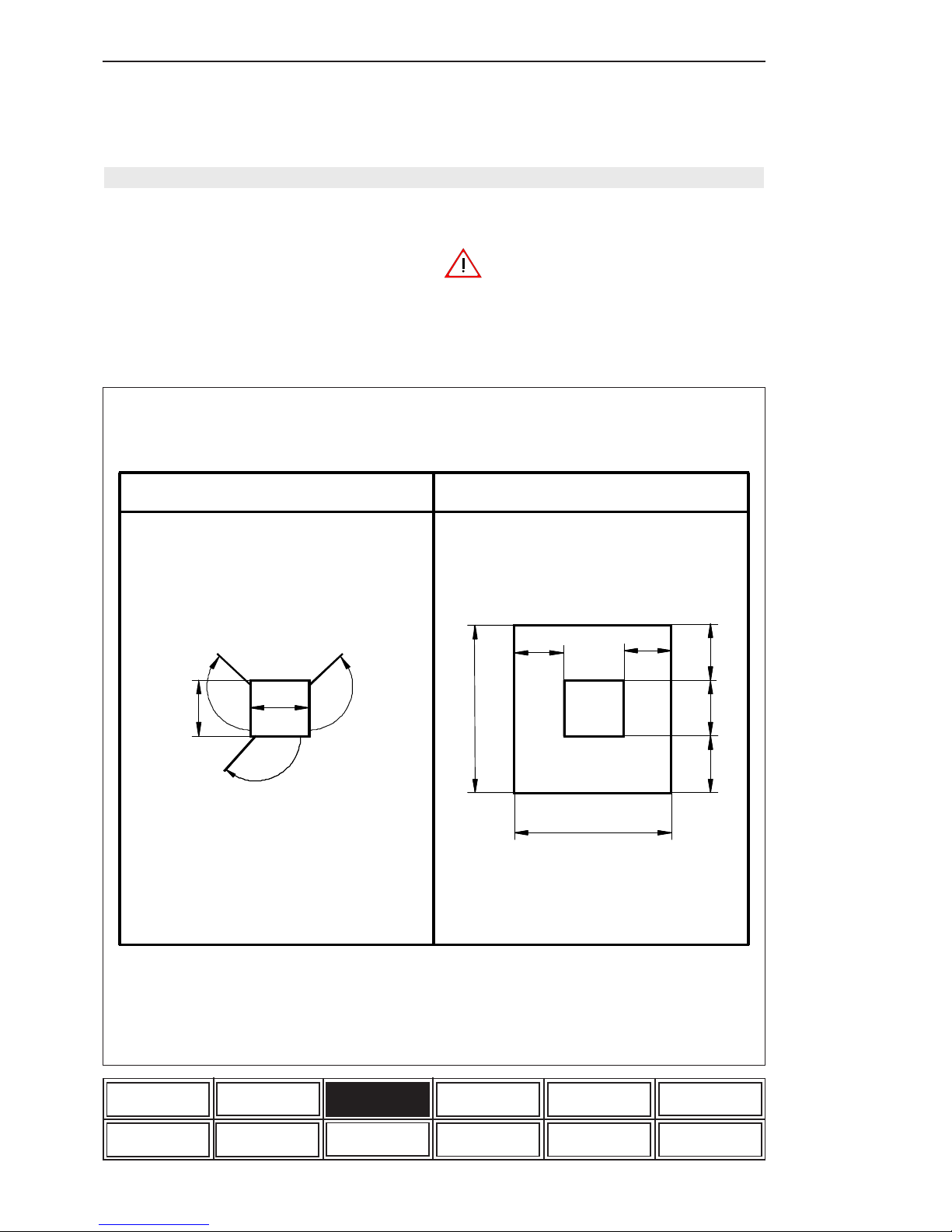
3.2.6 Space requirement (fig. 1)
Dimensions:
(Width x depth x height):
900mm x 780mm x 1800mm
For operating,- maintenance,- and repair work
please observe the necessary space requirements.
For adequate cooling of the xenon lamp,
take care that the air inlets and outlets at
the top and back side of the equipment
are not obstructed. Allow for the necessary space for operation, maintenance
and repair of the equipment.
Figure 1: Space requirement
Set-up area
Service area
H
x
H
R min
=2,5
x
x
Dimensions in
m
x
H
R min
H
0,9
2,9
1,0
1,0
1
,
0
1
,
0
Hx=1,8 H
R min
=2,5
x
X = XENOTEST ALPHA LM and ALPHA HIGH ENERGY
= unit height
= minimum laboratory height
0,9
2,9
1,0
1,0
2
,
8
1
,
0
0
,
8
1
,
0
0
,
8
x
Page 15
ATLAS Operating manual XENOTEST ALPHA / ALPHA HIGH ENERGY
Page 15
Safety instructions Unit set-up Unit description Start-up
Function Setting up tests Care and cleaning Maintenance
Options und accessory
ALPHA and HIGH
ENERGY features
Program example
List of options and
accessories
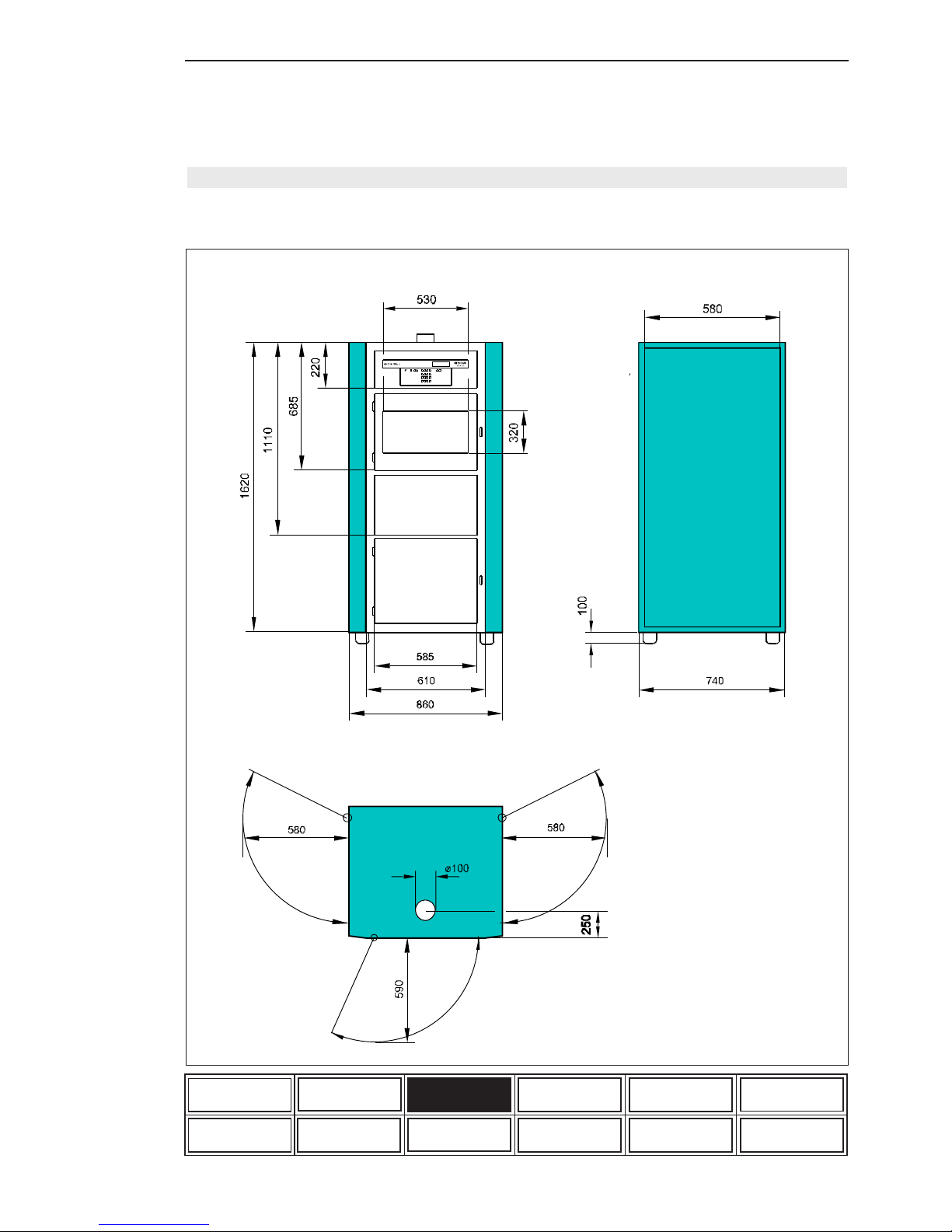
3.2.7 Unit dimensions (Fig. 2)
Figure 2: Unit dimensions (in mm)
Page 16
Operating manual XENOTEST ALPHA / ALPHA HIGH ENERGY ATLAS
Page 16
Safety instructions Unit set-up Unit description Start-up
Function Setting up tests Care and cleaning Maintenance
Options und accessory
ALPHA and HIGH
ENERGY features
Program example
List of options and
accessories
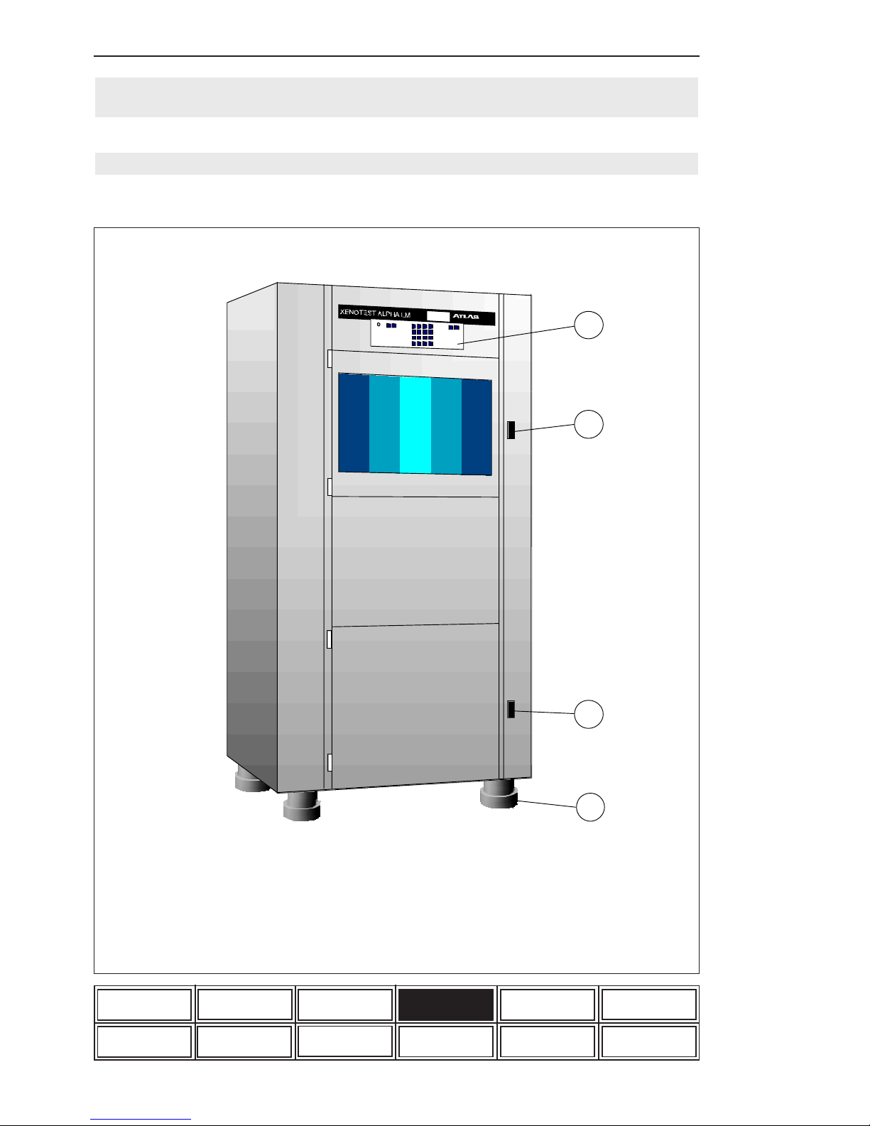
4. Description of the unit
Figure 3: Front side of equipment
1 Program control
2 Door locking test chamber
3 Door locking water tank
4 Height adjustable feet
4.1 Front side of equipment (fig. 3)
2
3
1
4
Page 17
ATLAS Operating manual XENOTEST ALPHA / ALPHA HIGH ENERGY
Page 17
Safety instructions Unit set-up Unit description Start-up
Function Setting up tests Care and cleaning Maintenance
Options und accessory
ALPHA and HIGH
ENERGY features
Program example
List of options and
accessories
The control panel on the front side of the apparatus
controls and regulates the course of the entered
weathering program. The program keyboard can
be locked during operation of the machine against
unauthorized access by means of a key-operated
switch.
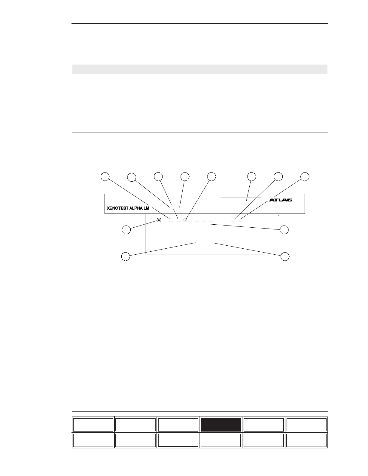
Figure 4: Program control
4.1.1 Program control (fig. 4)
1 4-line LCD display for user guidance and
data display
2 Data key for data display
3 Print key to print out the stored program,
parameter measurements and system
status from the printer
4 Program input keyboard
5 Enter key to confirm the input values
6 Escape key
7 Key-operated switch to allow locking
of the keyboard when the system is
running
8 START key
9 Green LED light comes on when main
switch is on
10 STOP key
11 Red LED flashes when the program is
interrupted with the STOP key or when
the system is defective. The red LED is
continuously on when certain limit values
are exceeded
12 Key to interrupt the rotation of the
specimen holder carousel during a running
program resp. to move the carousel when
a program is interrupted (When door is
closed)
1
2
3
4
56
7
8
9
10
11
12
0
1
Start Stop 123
456
789
0
ESCAPE ENTER
DATA PRINT
Page 18

Operating manual XENOTEST ALPHA / ALPHA HIGH ENERGY ATLAS
Page 18
Safety instructions Unit set-up Unit description Start-up
Function Setting up tests Care and cleaning Maintenance
Options und accessory
ALPHA and HIGH
ENERGY features
Program example
List of options and
accessories
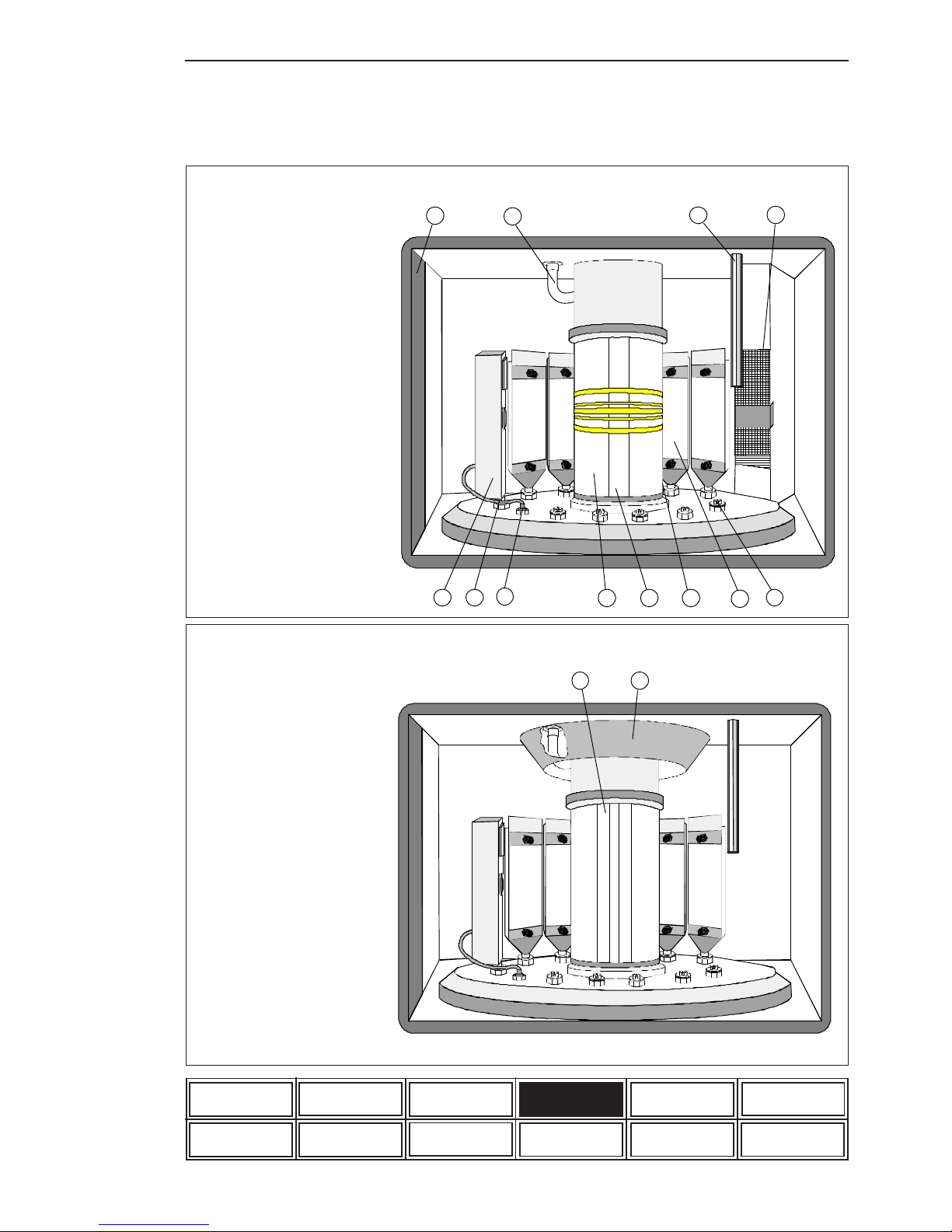
Open the test chamber by pressing the door lokking. A program is interrupted when the test chamber door is opened while a unit is running.
Are located in the test chamber :
- Chosen outer cylinder (1),
- Xenon lamp (2),
- Filter lantern (3),
- 11 sample holders (4),
- sample holder mountings (5).
Function:
The samples rotate around the lamp and filter lantern. In turning mode operation the samples are
turned by 180° per caroussell revolution.
Ventilation:
Test chamber and Xenon lamp are supplied by two
separate air flows. A uniform air ventilation is achieved by an appropriate air flow (fig. 10 ventilation
scheme).
Temperature, humidification and rain:
Air is taken from the test chamber by an air ex-
haust hose (6), warmed up by a heating system
and humidified in the humidifier, and then sent back
to the test chamber by an air supply hose (7).
The maximum chamber humidity can be adjusted
up to 95% r. h. depending on the preset temperature.
The rain bar (8) mounted in the test chamber is
used to spray ultra-pure water in cyclical intervals
and without any pressure on to the specimens.
Sensors:
At sample level a XENOSENSIV sensor (9) for
measuring the irradiance in the range between
300-400nm and the black standard temperature in
the surface temperature range up to 130°C can
be fitted to the test chamber by means of an ad-
apter (10) (fig. 31). The sensor is connected to
the program control via a connection socket (11).
If no sensor is used the end plug must be fitted to
the connection socket (fig. 36).
A sensor to measure the test chamber tempe-
rature and rel. humidity (12) is mounted in the
upper rear of the test chamber. The sensors combined with the program control guarantee control
of constant setting values.
Contrast to ALPHA:
Are locared in the test chamber:
- arc-shaped Xenon lamp (1)
Ventilation:
A uniform air ventilation of the sample area is achieved by an air conduction plate (2) (fig. 11 ventilation scheme).
4.1.3 Test chamber HIGH ENERGY (fig. 6)
4.1.2 Test chamber ALPHA (fig. 5)
Page 19
ATLAS Operating manual XENOTEST ALPHA / ALPHA HIGH ENERGY
Page 19
Safety instructions Unit set-up Unit description Start-up
Function Setting up tests Care and cleaning Maintenance
Options und accessory
ALPHA and HIGH
ENERGY features
Program example
List of options and
accessories
2 31
4
5
6
7
8
9
10
11
12
1 arc-shaped
Xenon lamp
2 Air conduction plate
Figure 6: Test chamber HIGH ENERGY
Figure 5: Test chamber ALPHA
1 Outer cylinder
2 Straight Xenon lamp
3 Filter lantern
4 Sample holder
5 Sample holder mounting
6 Air exhaust hose
7 Air supply hose
8 Rain bar
9 XENOSENSIV sensor
10 Adapter
11 Connection socket
12 Sensor for test chamber
temperature and rel.
humidity
21
Page 20
Operating manual XENOTEST ALPHA / ALPHA HIGH ENERGY ATLAS
Page 20
Safety instructions Unit set-up Unit description Start-up
Function Setting up tests Care and cleaning Maintenance
Options und accessory
ALPHA and HIGH
ENERGY features
Program example
List of options and
accessories
4.2 Right-hand apparatus side ALPHA and HIGH ENERGY (fig. 8)
4.3 Apparatus top ALPHA and HIGH ENERGY (fig. 8)
Data output:
Data of stored programs as well as current measuring values can be printed-out by a thermoprinter
(2). The interface (3) on the right-hand side of the
main switch provides for the data output and external computer control.
Electrical components:
The mains transformer of the humidifier (5), the
control transformer (6), a mains voltage inter-
ference filter (7) and the fuse base of the control voltage (8) are located below the test cham-
ber (4).
The power supply unit (10) of the lamp is moun-
ted below a protective wire mesh (9).
The mains transformer (11) and the lamp choke
(12) (not HIGH ENERGY unit) are located below
the power supply unit. The heating relay (14) is
seated next to the main contactor (13) and the
control of the test chamber fan (15). There is a
25 amps lamp fuse (16) protection and a 10 amps
heating fuse (17) protection. The operating hour
counter (18) records the operating time of the
equipment.
Ventilation:
The air intake for the lamp cooling (19) passes
through a filter pad in the equipment door.
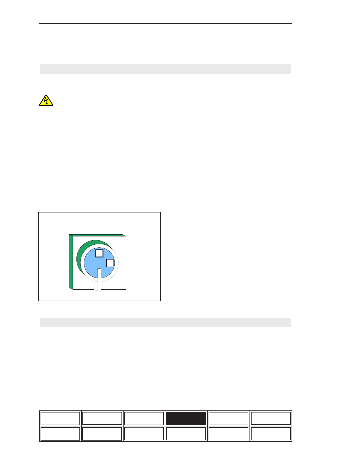
The main switch (1) (fig.7) is located on the upper
left of the unit. Use this switch to disconnect the
unit from the mains in case of trouble.
The lateral two-leaf doors of the unit
must only be opened by XENOTEST, or
an authorized customer service engineer
or an electrical specialist.
Contact with live parts of a unit connected to the mains may involve electrical
shock.
Before opening the lateral two-leaf doors
disconnect unit from the mains. Unplug
the connection socket and secure
against replugging!
Figure 7: Main switch
0
1
The exhaust air flow of the lamp is evacuated at
the top of the unit via an exhaust air socket
(20) to the open. (note figure 10 and 11,
ventilation schemes).
Page 21

ATLAS Operating manual XENOTEST ALPHA / ALPHA HIGH ENERGY
Page 21
Safety instructions Unit set-up Unit description Start-up
Function Setting up tests Care and cleaning Maintenance
Options und accessory
ALPHA and HIGH
ENERGY features
Program example
List of options and
accessories
Figure 8: Right hand apparatus side
0
1234 56
2
3
1
4
5
6
7
8
9
10
11
12
13
14
15
16
17
18
19
20
Before opening the lateral two-leaf doors disconnect unit from the mains.
Unplug the connection socket and secure against replugging!
1 Main switch
2 Thermo printer
3 Interface RS 232 / RS485
4 Test chamber
5 Transformer humidifier
6 Control transformer
7 Mains voltage interference filter
8 Fuse base of the control voltage
9 Protective wire mesh
10 Power supply unit for lamp
11 Mains transformer
12 Lamp choke (not HIGH ENERGY)
13 Main contactor
14 Heating relay
15 Control test chamber fan
16 Lamp fuse (2 pcs.), 25A
17 Heating fues (2 pcs.), 10A
18 Operating hours meter
19 Air intake for lamp cooling
20 Exhaust air socket lamp cooling
Page 22

Operating manual XENOTEST ALPHA / ALPHA HIGH ENERGY ATLAS
Page 22
Safety instructions Unit set-up Unit description Start-up
Function Setting up tests Care and cleaning Maintenance
Options und accessory
ALPHA and HIGH
ENERGY features
Program example
List of options and
accessories
4.4 Left-hand apparatus side ALPHA and HIGH ENERGY (fig. 9)
The lateral two-leaf doors of the unit
must only be opened by XENOTEST, or
an authorized customer service engineer or an electrical specialist.
Contact with live parts of a unit connected to the mains may involve electrical
shock.
Before opening the lateral two-leaf
doors disconnect unit from the mains.
Unplug the connection socket and secure against replugging!
Ventilation and heating:
The climatic fan (2) is located on top of the test
chamber (1) and takes air in from the test chamber
through a filter mat (3).The air is warmed up by a
heating system (4) and led to the test chamber
through a ventilation duct.
Humidification:
Heated air is taken out of the test chamberand led
to the humidifier (6) through a flexible, heat
resistant hose (5). The humidified air is returned
to the test chamber via four humidification hoses
(7) (note fig. 10 and 11 ventilation schemes). The
water supply to the humidifier is adjusted by a
valve (8).
Control of basic parameters
The sensor for test chamber temperature and
rel. humidity (fig. 5 Point 12) transmits the actual
values taken from the exhaust air flow of the test
chamber to the program control system. With a
target/actual comparison the requested test
parameters are adjusted permanently by adjusting
elements.
With an inserted Xenosensiv sensor (note fig. 5
Point 9) the slip ring collector (9) seated below
the test chamber transmits the measurd values to
the program control.
The fresh air supply to the test chamber is
controlled by an air flap which is adjusted by a flap
motor (10).
The ignition unit (11) in conjunction with the power
supply unit (note fig.8 Point 10) ignites the Xenon
lamp. The caroussel motor (12) drives the
caroussel in the test chamber. The turning- and
non-turning mode is switched on and off by a lifting
magnet (13). The function of the caroussel is
monitored by an inductive proximity sensor (14).
Rain:
The rain pump (15) provides the rain bar in he
test chamber with ultra-pure water. The inlet and
outlet lines of the humidifier, the water return line
from the test chamber and the supply line of the
water pump are led through the top of the water
tank (16). The water tank is emptied through the
water outlet tube (17).
4.5 Apparatus rear panel of ALPHA and HIGH ENERGY (fig. 9)
At the apparatus bottom rear panel the water tank
can be filled through a water supply tube (18).
The lamp exhaust air can be led to the open via a
flexible, heat resistant hose (19).
Page 23

ATLAS Operating manual XENOTEST ALPHA / ALPHA HIGH ENERGY
Page 23
Safety instructions Unit set-up Unit description Start-up
Function Setting up tests Care and cleaning Maintenance
Options und accessory
ALPHA and HIGH
ENERGY features
Program example
List of options and
accessories
Figure 9: Left hand apparatus side
2
3
1
4
5
6
8
9
10
11
12
13
14
15
16
17
18
19
7
20
Before opening the lateral two-leaf doors disconnect unit from the mains.
Unplug the connection socket and secure against replugging!
1 Test chamber
2 Climatic fan
3 Filter mat
4 Heating
5 Flexible, heat resistant supply hose
to humidifier
6 Humidifier
7 Humidification hoses (4x)
8 Valve
9 Slip ring collector
10 Flap motor ventilation flap
11 Ignition unit
12 Caroussel motor
13 Lifting magnet
14 Sensor for carussel speed
15 Rain pump
16 Water tank
17 Water outlet
18 Water inlet
19 Flexible, heat resistant air outlet hose
20 Fan lamp cooling
Page 24

Operating manual XENOTEST ALPHA / ALPHA HIGH ENERGY ATLAS
Page 24
Safety instructions Unit set-up Unit description Start-up
Function Setting up tests Care and cleaning Maintenance
Options und accessory
ALPHA and HIGH
ENERGY features
Program example
List of options and
accessories
1) Lamp cooling:
Fan (1) produces the exhaust air flow (2), which
cools down the xenon lamp.
2) Test chamber (fresh air operation):
The ventilation circuit of the test chamber receives fresh air (3) through a filter mat (4) at the left
side of the unit. The quantity of fresh air is controlled by an air inlet flap (5) and warmed up by a
heating system (6). The climatic fan (7) transmits the air humidified by the humidifier via air in-
take tubes (8) to the test chamber (9).
In the ALPHA, air flows from the air duct at the
rear of the unit to the samples (10). A sensor (12)
measures the temperature and relative humidity
of the test chamber exhaust air (11) under permanent target/value comparison. Via an exhaust
air hose (13) the air is evacuated to the outside.
4.7 Ventilation circuits HIGH ENERGY (fig.11)
Contrasts to ALPHA:
In the HIGH ENERGY unit air is directed via an air
duct (1) from the top along the samples (2).
4.6 Ventilation circuits ALPHA (fig.10)
3) Test chamber (air circulation):
During the air circulation mode the air flap (5) is
closed within the adjusting range (14) and the
air flow (15) is directed as described.
Page 25

ATLAS Operating manual XENOTEST ALPHA / ALPHA HIGH ENERGY
Page 25
Safety instructions Unit set-up Unit description Start-up
Function Setting up tests Care and cleaning Maintenance
Options und accessory
ALPHA and HIGH
ENERGY features
Program example
List of options and
accessories
Figure 10: Ventilation scheme ALPHA
(seen from top of the unit)
Figure 11: Ventilation scheme HIGH ENERGY
(seen from top of the unit)
2
11
1
9
12
15
8
6
5
4
3
1013
14
7
1 Fan lamp cooling
2 Lamp exhaust air flow
3 Fresh air inlet
4 Filter mat
5 Flap air inlet
6 Heating
7 Climatic fan
8 Air intake tubes from humidifier
9 Test chamber
10 Samples
11 Test chamber air
12 Sensor for test chamber temperature and
rel. humidity
13 Exhaust air hose
14 Flap adjusting range
15 Circulated air
2
1
1 Air duct
2 Samples
Page 26

Page 26
Operating manual XENOTEST ALPHA / ALPHA HIGH ENERGY ATLAS
Safety instructions Unit set-up Unit description Start-up
Function Setting up tests Care and cleaning Maintenance
Options und accessory
ALPHA and HIGH
ENERGY features
Program example
List of options and
accessories
Unit components which are installed by ATLAS.
5.1.1 Rain and humidity function (fig. 12)
5.1 Options
1 Water tank
2 Water inlet socket
3 Level switch
4 Solenoid switch
5 Diving pump
6 Humidifier
7 Valve
8 Rain pump
9 Rain ring bar
10 Test chamber return pipe
11 Water outlet socket
Figure 12: Water circuit
The water tank (1) is filled through a water inlet
socket (2). The overflow is regulated by a level
switch (3), water shortage is indicated on the
display by a solenoid switch (4). A diving pump
(5) is located in the water tank which supplies the
two humidifiers (6). The supply amount is
adjustable by a valve (7).
The rain pump (8) supplies water to the rain ring
bar (9). Excess water is returned to the water
tank via a return pipe (10) or evacuated outside.
The water tank can be emptied through the water
outlet socket (11).
5. Options and accessories
2
3
1
4
5
6
7
8
9
10
11
Page 27

Page 27
ATLAS Operating manual XENOTEST ALPHA / ALPHA HIGH ENERGY
Safety instructions Unit set-up Unit description Start-up
Function Setting up tests Care and cleaning Maintenance
Options und accessory
ALPHA and HIGH
ENERGY features
Program example
List of options and
accessories
5.1.2 Printer (fig. 13)
The stored programs and the measured data for
the running program can be printed out by the thermal printer. By pressing the „PRINT“-key during
the running program the printer parameters are
indicated on the display:
Equipment data = 1
Program parameter = 2
Current parameter = 3
1
2
3
4
5
The requested parameters are entered via the
keyboard of the control panel. When selecting
menu item 3 „Current parameters“ the printout
interval in minutes can be entered via the keyboard.
1 LED „ALARM“
2 Key LINE FEED/ENTER
3 Locking latch
4 Key MENU/SELECT
5 Paper tear-off bar
Figure 13: Printer
Menu/Select
This key has two functions. If this key is depressed
for more than 3 seconds during operation the
printer will change to the menu program allowing
modification of the printer parameters. In the menu
program "Select" is used to chose the various
equipment parameters.
Paper tear-off bar :
To tear off the paper strap, pull paper quickly
upwards from one side to the other.
LED-Alarm:
Lighting up of the LED signals the end of the
printing paper.
Line Feed/Enter:
This key has two functions. During operation „Line
Feed“ is used for manual paper transport, in the
menu program, „Enter“ is used to take over and
store the parameters chosen with „Select“.
By pressing the locking latch to the right the
frontplate swings out. This provides access to the
paper roll for exchange.
Page 28

Page 28
Operating manual XENOTEST ALPHA / ALPHA HIGH ENERGY ATLAS
Safety instructions Unit set-up Unit description Start-up
Function Setting up tests Care and cleaning Maintenance
Options und accessory
ALPHA and HIGH
ENERGY features
Program example
List of options and
accessories
The printer parameters (fig. 13) are
preset in the factory and must not be
changed.
Figure 14: Printer parameters
PRINT INTERVAL
PRINTER ADDRESS
DATA FORMAT
BAUDRATE
INTERFACE
CHARACTER SET
CHARACTERS/LINE
PRINT FORMAT
PRINT STRENGTH
MODE
NO
00-PRINT ALWAYS
8 NO PARITY
NORMAL
ON LINE
40
9600
SERIAL
NATIONAL LANGUAGE
.....+.....
Change of printer parameters:
1. For access to the menu, press „MENU/
SELECT“ key for more than 3 seconds.The
following message will be printed out.
ACTUAL PARAMETER?
PRESS „ENTER“
2. Press „LINE FEED/ENTER“ key. The printer
prints out current parameters and shows the
following message.
CHANGE OF PARAMETERS?
3. To change the printer parameters, press
„LINE FEED/ENTER“ and „MENU/SELECT“
for more than 4 seconds. Afterwards the single parameters are listed and can be confirmed by pressing „LINE FEED/ENTER“
or be changed by pressing „MENU/
SELECT“.
4. To exit the menu programm, press „MENU/
SELECT“ and „LINE FEED/ENTER“ keys
simultaneously, or the program is
automatically terminated after 3 minutes
without actuating any key.
Page 29

Page 29
ATLAS Operating manual XENOTEST ALPHA / ALPHA HIGH ENERGY
Safety instructions Unit set-up Unit description Start-up
Function Setting up tests Care and cleaning Maintenance
Options und accessory
ALPHA and HIGH
ENERGY features
Program example
List of options and
accessories
Change of paper roll: (fig.15)
Figure 15
Figure 16
2
1
1 Paper roll
2 Paper inlet slot
1. Press locking latch to the right and swing
front panel open.
2. Remove old paper roll.
3. Fit new paper roll in such way that it turns
clockwise when unwinding.
4. Cut edges of the paper and insert paperroll (note fig. 15).
5. Keep „LINE FEED/ENTER“ key
depressed until the beginning of the paper
appears below the tear-off edge.
6. Close front door (locking latch must
engage), the LED "ALARM" will go out,
and the printer is ready for operation.
5.1.3 Mains matching
transformer (fig.16)
The mains transformer is needed for specific mains
adaptations in the various countries and is fitted to
the bottom right side of the unit (note fig. 8 Point
11) .
5.1.4 Interface
The unit supports alternatively an RS 232 or RS
485 interface to transmit measurement data to a
computer whilst a program is in progress.
With the accessory-package XENOVIEW consisting of:
- connection cable
- software
- operating manual
the interface can be driven.
(serial 9-pole Id. No. 56076813)
(serial 25-pole Id.-No. 56076812)
Connect the interface of the unit with the serial
interface of the computer.
5.1.5 Turning mode gear
In turning mode operation the samples are moved
continuously around the lamp being permanently
exposed to the light source.
The turning mode gear is used to turn the samples,
each sample holder being turned by 180° after each
caroussel revolution. As a consequence, the sample
is exposed in a light/dark phase.
The average irradiance and black standard
temperature is calculated from the values measured
by the XENOSENSIV sensor running in the nonturning mode and from factors and formulas stored
in the program control to then be shown in the
display.
Page 30

Page 30
Operating manual XENOTEST ALPHA / ALPHA HIGH ENERGY ATLAS
Safety instructions Unit set-up Unit description Start-up
Function Setting up tests Care and cleaning Maintenance
Options und accessory
ALPHA and HIGH
ENERGY features
Program example
List of options and
accessories
5.2 Accessory
Helpful accessories for the operation with ALPHA and HIGH ENERGY.
For reference numbers please refer to the table on page 61.
Consists of a filter lantern (2) with 5 absorbers
(ALPHA) or 1 absorber (HIGH ENERGY) (3), and
10 filters (4) with corresponding outer cylinder
(5).
Different spectral energy distribution values can be obtained by varying the optical filters and the outer cylinder (see
fig. 18, 19, 20 and 21).
A) XENOCHROME 270 (I, 27)
with quartz cylinder,
B) XENOCHROME 300 (II, 30)
with UV special glass cylinder (Suprax),
C) XENOCHROME 320 (III)
with UV special glass cylinder (Suprax),
The ALPHA and HIGH ENERGY are used to simulate the solar or global spectrum with filtered
xenon lamp radiation. To realise the various stan-
dards and test specifications a XENOCHROMEand absorption filter systems are at your disposal.
5.2.1 Filter system
1. XENOCHROME filter system (fig. 17)
Identification of XENOCHROME filters:
identification with the numbers I,II,III or 27, 30
und 32 at the bottom end of the filter.
Page 31

Page 31
ATLAS Operating manual XENOTEST ALPHA / ALPHA HIGH ENERGY
Safety instructions Unit set-up Unit description Start-up
Function Setting up tests Care and cleaning Maintenance
Options und accessory
ALPHA and HIGH
ENERGY features
Program example
List of options and
accessories
metal absorber which absorbs them. The air flow
along the xenon lamp and the absorber plates in
the optical filter system dissipates the heat.
Figure 17: XENOCHROME filter system ALPHA and path of radiation
1 Xenon lamp
2 Filter lantern
3 Absorbers (5x)
4 Filters (10x)
5 Outer cylinder
UV + VI S
IR
IR
1
2
3
4
5
UV + VIS
Path of radiation:
The fraction of UV and light radiation which strike
the coated filters pass through the outer cylinder
towards the specimen level, while the IR-radiation
parts are reflected and directed on to the black
Page 32

Page 32
Operating manual XENOTEST ALPHA / ALPHA HIGH ENERGY ATLAS
Safety instructions Unit set-up Unit description Start-up
Function Setting up tests Care and cleaning Maintenance
Options und accessory
ALPHA and HIGH
ENERGY features
Program example
List of options and
accessories
Figure 18: ALPHA
Spectral energy distribution in the wavelength range 200-800 nm
XENOCHROME 300 filter system with Suprax outer cylinder and CIE 85
Figure 19: ALPHA
Spectral energy distribution in the wavelength range 200-800 nm
XENOCHROME 270 filter system with quartz outer cylinder
XENOCHROME 320 filter system with Suprax outer cylinder
0
2
4
6
8
10
12
200 300 400 500 600 700 800
Wavelength [nm]
Irradiance [W/m² x nm]
XENOCHROME 300
CIE 85
XENOTEST ALPHA
XENOCHROME filter variations:
0
2
4
6
8
10
12
200 300 400 500 600 700 800
Wavelength [nm]
Irradiance [W/m² x nm]
XENOCHROME 270
XENOCHROME 320
XENOTEST ALPHA
XENOCHROME filter variations:
Page 33

Page 33
ATLAS Operating manual XENOTEST ALPHA / ALPHA HIGH ENERGY
Safety instructions Unit set-up Unit description Start-up
Function Setting up tests Care and cleaning Maintenance
Options und accessory
ALPHA and HIGH
ENERGY features
Program example
List of options and
accessories
Figure 20: HIGH ENERGY
Spectral energy distribution in the wavelength range 200-800 nm
XENOCHROME 300 filter system with Suprax outer cylinder and CIE 85
Figure 21: HIGH ENERGY
Spectral energy distribution in the wavelength range 200-800 nm
XENOCHROME 270 filter system with quartz outer cylinder
XENOCHROME 320 filter system with Suprax outer cylinder
0
2
4
6
8
10
12
14
16
200 300 400 500 600 700 800
Wavelength [nm]
Irradiance [W/m² x nm]
XENOCHROME 300
CIE 85
XENOTEST ALPHA HIGH ENERGY
XENOCHROME filter variations:
0
2
4
6
8
10
12
14
16
200 300 400 500 600 700 800
Wavelength [nm]
Irradiance [W/m² x nm]
XENOCHROME 270
XENOCHROME 320
XENOTEST ALPHA HIGH ENERGY
XENOCHROME filter variations:
Page 34

Page 34
Operating manual XENOTEST ALPHA / ALPHA HIGH ENERGY ATLAS
Safety instructions Unit set-up Unit description Start-up
Function Setting up tests Care and cleaning Maintenance
Options und accessory
ALPHA and HIGH
ENERGY features
Program example
List of options and
accessories
2. Absorption filter system (fig. 22, 23 and 24)
The absorption filter system (fig. 22) consists of a
filter lantern (2) with 7 optical filters (3), which
are inserted next to each other, and an outer
cylinder of special UV glass (Suprax) (4).
Different spectral energy distribution values can be obtained by varying the optical filters and the outer cylinder (see
fig. 25 as an example).
Figure 22: Absorption filter system
B) Sunlight outdoors (fig. 23):
To simulate the exposure „sunlight outdoors“
(requirement for the testing of weather fastness
of textiles and leather according to ISO 105 B04
and corresponding to national standards such as
DIN 54071) one of the 7 IR filters is replaced by
a black glass filter.
1
2
3
4
1 Xenon lamp
2 Filter lantern
3 Filter segments (7x)
4 Out Suprax cylinder
Variants of the Absorption filter system:
(Not for HIGH ENERGY models)
A) Sunlight behind window glass (fig. 22):
To simulate the exposure „sunlight behind
window glass“ (requirement for the testing of
light fastness of textiles and leather according to
ISO 105 B02 and corresponding to national
standards (such as DIN 54004) 7 IR filters are
inserted into the filter lantern.
Abbildung 24
Figure 23
C) Light fastness of car interior fittings:
(fig. 24)
For a special test method according to ISO 105B06 resp. DIN 75202 (light fastness of car
interiors) a mixture of 4 IR- and 3 window glass
filters can be inserted into the lantern.
Page 35

Page 35
ATLAS Operating manual XENOTEST ALPHA / ALPHA HIGH ENERGY
Safety instructions Unit set-up Unit description Start-up
Function Setting up tests Care and cleaning Maintenance
Options und accessory
ALPHA and HIGH
ENERGY features
Program example
List of options and
accessories
Useful lifetime of absorption filters and outer cylinders:
IR absorption filters:
Exchange every 500 hours one of the 7 IR filters
against a new one. For distinction the filters are
marked at their bottom end with the numbers 1-7,
which allows recognizing their position.
UV black glass filter:
After 3500 hours.
Window glass filters:
Exchange separately in a rythm of 500 hours.
Outer cylinder of UV special glass (Suprax):
Exchange every 15 000 hours.
Outer cylinder of quartz glass:
Non ageing.
Figure 25: ALPHA
Spectral energy distribution in the wavelength range 200-800 nm
Absorption filter system with 7 IR filters and Suprax outer cylinder
0
2
4
6
8
10
12
200 300 400 500 600 700 800
Wavelength [nm]
Irradiance [W/m² x nm]
7 IR-Filter
XENOTEST ALPHA
Absorption filters:
Page 36

Page 36
Operating manual XENOTEST ALPHA / ALPHA HIGH ENERGY ATLAS
Safety instructions Unit set-up Unit description Start-up
Function Setting up tests Care and cleaning Maintenance
Options und accessory
ALPHA and HIGH
ENERGY features
Program example
List of options and
accessories
Figure 26: Standard sample holder
5.2.2 Standard set of sample
holders (fig. 26)
The standard set of sample holders (Id.-No.
56075142) consists of 11 sample holders with the
dimensions 135mm x 45mm x 3mm maximum
sample thickness.
Fitting:
1. Insert the specimen into the sample holder.
2. Fix the specimen with the two screws.
Figure 27: Special holder for thick
specimens
5.2.3 Special sample holder for
thick specimens (fig. 27)
The special sample holder set (No. 56075143 =
11 pieces) is used for samples with the dimensions
135mm x 45mm up to max.15mm thickness.
The special sample holder may only be
used in non-turning mode.
Fitting:
1. Adjust the special sample holder with a
screw driver to the required specimen
thickness.
2. Fit the sample between the two plates and
tighten with the knurled screws.
Page 37

Page 37
ATLAS Operating manual XENOTEST ALPHA / ALPHA HIGH ENERGY
Safety instructions Unit set-up Unit description Start-up
Function Setting up tests Care and cleaning Maintenance
Options und accessory
ALPHA and HIGH
ENERGY features
Program example
List of options and
accessories
The sample holder for blue scales (No. 56001452)
can be fitted into the ALPHA and HIGH ENERGY
unit.
Fitting:
1. Pull the two clamps (1) slightly aside and
remove the inner blue scale mounting (2)
towards the bottom.
2. Fix specimens and secure with the little
clamps.
3. Insert mounting, secure it and slip on top
part (3) from above sliding it towards the
bottom.
4. Insert sample holder into the machine and
push top part upwards until the holding
clamps (4) snap into position.
5.2.4 Sample holder for blue
scale (fig. 28)
Figure 28: sample holder for blue scale
1 Lateral clamps
2 Blue scale mounting
3 Top p art
4 Holding clamps
2
3
1
4
5.2.6 Software package
XENOVIEW
Software for transfer of measuring data to a PC.
- XENOVIEW, serial 9-pole (No. 56076813)
- XENOVIEW, serial 25-pole (No. 56076812)
5.2.5 Cover plates (fig. 29)
To make contrast between the irradiated and nonirradiated sections of the specimens clearly visible, the set of cover plates with 11 pieces ea. (id.
no. 56075155) is available with 3 differently sized
apertures of 9mm, 18mm and 27mm.
Fitting:
1. Insert specimen into the cover plate. For a
lighttight fitting insert cover plates with the
U-bent edges facing the sample holder.
2. Screw on the cover plates with the two knurled screws.
Figure 29: cover plate
Page 38

Page 38
Operating manual XENOTEST ALPHA / ALPHA HIGH ENERGY ATLAS
Safety instructions Unit set-up Unit description Start-up
Function Setting up tests Care and cleaning Maintenance
Options und accessory
ALPHA and HIGH
ENERGY features
Program example
List of options and
accessories
Figure 31: Adapter for XENOSENSIV sensor
The adapter (No. 56075643) is used to fix the
XENOSENSIV sensor in the test chamber.
5.2.8 Adapter for XENOSENSIV sensor (fig. 31)
5.2.7 XENOSENSIV sensor
(fig. 30)
The XENOSENSIV sensor (No. 56076841) collects
the values of irradiation in a wavelength range of
300-400 nm as well as the values of the black standard temperature in a surface temperature range
up to 130 °C at specimen level.
The XENOSENSIV sensor enables constant regulation of chosen irradiation and black standard
temperature values.
5.2.9 Calibration adapter and
end plug (fig. 32)
Figure 32: Calibration adapter and
end plug
To calibrate the XENOSENSIV sensor on a second XENOSENSIV master sensor (Software
documentation chapt. 1.3 A) a calibration adapter
(No. 56075992) is used. If no sensor is inserted,
the contact plug in the test chamber is protected
by an end plug.
Figure 30: XENOSENSIV sensor
S
S
T
E
Page 39

Page 39
ATLAS Operating manual XENOTEST ALPHA / ALPHA HIGH ENERGY
Safety instructions Unit set-up Unit description Start-up
Function Setting up tests Care and cleaning Maintenance
Options und accessory
ALPHA and HIGH
ENERGY features
Program example
List of options and
accessories
6. Start-up
6.1.1 Fitting the filters to the lantern
6.1 Filter variations
Wear cotton gloves to insert the filters in
order to avoid finger marks on the glass.
XENOCHROME filters:
Insert the 10 filters from the top into the lantern.
Turn into position.
Absorption filters:
Insert 7 filters from the top into the lantern.
Filter / Model XENOTEST ALPHA XENOTEST ALPHA HIGH ENERGY
XENOCHROME filters Outer cylinder with goldrings
Filter lantern with 5 absorbers
Straight lamp
Outer cylinder with goldrings
Filter lantern with 1 absorber
Omega-shaped lamp
XENOCHROME 270 (10 pcs.)
(identification I or 27)
Quartz outer cylinder
XENOCHROME 300 (10 pcs.)
(identification II or 30)
UV special glass cylinder (Suprax)
XENOCHROME 320 (10 pcs.)
(identification III or 32)
UV special glass cylinder (Suprax)
Absorption filters Outer cylinder with goldrings
Filter lantern without absorbers
Straight lamp
Outer cylinder without goldrings
Filter lantern with absorbers
Omega-shaped lamp
7 IR filter
(Green cutaway view)
UV special glass cylinder (Suprax)
10 window glas filter
(Light green cutaway view)
UV special glass cylinder (Suprax)
6 IR filter
(Green cutaway view)
1 Black filter
(Black filter)
UV special glass cylinder (Suprax)
4 IR filter
(Green cutaway view)
3 window glass filter
(Light green cutaway view)
UV special glass cylinder (Suprax)
Page 40

Page 40
Operating manual XENOTEST ALPHA / ALPHA HIGH ENERGY ATLAS
Safety instructions Unit set-up Unit description Start-up
Function Setting up tests Care and cleaning Maintenance
Options und accessory
ALPHA and HIGH
ENERGY features
Program example
List of options and
accessories
When filters are not inserted overheating
may occur and damage specimens and
unit.
Always insert filters!
11. Wear gloves to push Xenon lamp into the
bottom lamp socket. Take care to correctly
align the distance between absorber and
lamp (fig. 33).
Only applicable for unit version ALPHA:
Fit the lamp centering piece and connect lamp
contacts.
12. Close the casing cover and place the ex-
haust tube on to the air exhaust adapter.
6.1.2 Insertion of the exposure
system (fig. 33)
Contact with live parts of a unit connected to the mains may involve electrical
shock.
Switch the unit off and unplug the connection socket. Secure against replugging!
Please observe the possible filter
variations in chapter 6.1.
1. Switch the unit off!
2. remove exhaust air pipe on top of the unit,
3. fold up cover (1), lift spacer tube (2) and
put aside.
Only applicable for unit version ALPHA:
Put aside contact (3) of the lamp, remove lamp
centering piece (4),
4. wear gloves to carefully remove lamp (5),
5. remove filter lantern (6).
6. unscrew the 4 securing screws (7) of the
flange tube (8). Open the test chamber
door and move the connection piece of the
unscrewed flange tube slightly upwards,
7. fit lower sealing ring (9) and insert outer
cylinder (10) from the front through the
test chamber door,
Only applicable for unit version ALPHA:
Insert outer cylinder with goldrings in such way
that the inscription "UNTEN" is readable.
8. Insert upper sealing ring (11) into con-
nection piece and slide this on outer cylinder and sealing.
9. Fix upper flange with 4 securing screws
from the top through the casing cover.
10. Place filter lantern with filters into the outer
cylinder.
6.1.3 Insert the lamp and the
filter lantern (fig. 33)
Before starting operation:
Reset lamp age to 0 (see software documentation).
To exchange lamp proceed as described in chapter
6.1.2 for the start-up.
Exchange of lamps: points 1-4, 11-12.
Exchange of lantern: points1-5, 10-12.
6.1.4 Exchange of lamp
Optimize radiation constancy:
Exchange lamp in an interval of 1500 hours.
During operation:
The recommended exchange after 1500 operating
hours is signalled by the program control.
The lamp age can be retrieved via the DATA key.
Page 41

Page 41
ATLAS Operating manual XENOTEST ALPHA / ALPHA HIGH ENERGY
Safety instructions Unit set-up Unit description Start-up
Function Setting up tests Care and cleaning Maintenance
Options und accessory
ALPHA and HIGH
ENERGY features
Program example
List of options and
accessories
1
2
3
4
5
6
7
8
9
10
11
UNTEN
Figure 33: Insertion of the exposure system
7 Securing screws flange tube (4x)
8 Flange tube
9 Bottom sealing ring
10 Outer cylinder
11 Top sealing ring
1 Casing cover
2 Spacer tube
3 Lamp contacts
4 Lamp centering piece
5 Xenon lamp
6 Filter lantern
ALPHA HIGH ENERGY
Page 42
Page 42
Operating manual XENOTEST ALPHA / ALPHA HIGH ENERGY ATLAS
Safety instructions Unit set-up Unit description Start-up
Function Setting up tests Care and cleaning Maintenance
Options und accessory
ALPHA and HIGH
ENERGY features
Program example
List of options and
accessories
6.2 Water supply
For the rain and humidity function ultrapure water is needed. Please take care
of the necessary water quality (chapt.
3.2.4)!
Supply:
By supply line:
fill the water tank (fig.9) with a pressure-resistant
hose (inner diameter 13mm, max. 3bar pressure).
Without supply line:
open bottom door at front panel of the unit and fill
the water tank manually.
Function:
When the tank is full, the supply line is closed via
a float valve. Any water shortage occurring in the
tank is shown in the display.
6.3 Insertion of the XENOSENSIV sensor (fig. 34)
Fitting:
1. Fit the XENOSENSIV sensor (2) with the
two fixing screws (1) to the adapter (3).
2. Insert the fixed sensor beside the coupler
socket to the specimen caroussel (see fig.
5 point 11).
3. Connect plug to the coupler socket of the
test chamber by means of the connection
cable (4).
Function:
The continuously rotating sensor (at sample level)
collects the measuring values of the irradiance
(5) in the wavelength range of 300-400nm as well
as the measuring values of the black standard
temperature (6) in the range of the ambient temperature up to 130°C at sample level.
The measuring values are used by the program
control to adjust the preset parameter values.
Page 43

Page 43
ATLAS Operating manual XENOTEST ALPHA / ALPHA HIGH ENERGY
Safety instructions Unit set-up Unit description Start-up
Function Setting up tests Care and cleaning Maintenance
Options und accessory
ALPHA and HIGH
ENERGY features
Program example
List of options and
accessories
4 Connection cable
5 Measuring of irradiance
6 Measuring of black standard temperature
Figure 34: Insertion of the XENOSENSIV sensor
1 Fixing screws (2x)
2 XENOSENSIV sensor
3 Adapter
4
5
6
3
1
2
Page 44

Page 44
Operating manual XENOTEST ALPHA / ALPHA HIGH ENERGY ATLAS
Safety instructions Unit set-up Unit description Start-up
Function Setting up tests Care and cleaning Maintenance
Options und accessory
ALPHA and HIGH
ENERGY features
Program example
List of options and
accessories
6.4.1 Insertion of the end plug
(fig. 36)
6.4 Adjustment of the XENO SENSIV sensor
For the adjustment of the XENOSENSIVsensor a master sensor is necessary.
Procedure:
1. Fix the sensors to the adapters
(chapt.6.3).
2. Insert the two sensors on to the mountings
next to the coupler socket in the test
chamber.
3. Connect the sensors to the XENOSENSIV
sensor sockets (1,2) of the calibration adapter (fig. 35).
Please take care that the XENOSENSIV
sensor sockets of the calibration adapter are assigned to the corresponding
sensors.
4. Then connect the calibration adapter with
the plug-type connector (3) to the coupler
socket in the test chamber.
5. Set switch on the calibration adapter to position "SST" to calibrate the black standard
temperature or to E for the irradiance.
6. Start calibration program.
If no XENOSENSIV sensor is fitted, the coupler
socket in the test chamber is to be secured with an
adapter plug.
1 Master sensor socket
2 XENOSENSIV sensor socket
3 Plug-type connector
Figure 36: End plug
S
S
T
E
1
2
3
Figure 35: Calibration adapter
Page 45

Page 45
ATLAS Operating manual XENOTEST ALPHA / ALPHA HIGH ENERGY
Safety instructions Unit set-up Unit description Start-up
Function Setting up tests Care and cleaning Maintenance
Options und accessory
ALPHA and HIGH
ENERGY features
Program example
List of options and
accessories
7. Function
Control:
During the lifetime of the lamp (1500 hours) the
irradiance is kept constant at the set value.
Deviations of the irradiance are identified by the
XENOSENSIV sensor and compensated by the
control system.
Depending on the selected filter system different
spectral energy distributions may occur (fig. 18, 19,
20, 21 and 25).
7.1.2 Black standard
temperature
Measurig:
With the XENOSENSIV sensor.
Range of adjustment:
In dependence of the irradiance and the ambient
temperature up to max. 130°C via the control
system.
Control:
Control is effected by the fan speed, i.e. by the air
flow rate in the test chamber.
7.1.3 Fan speed
Range of adjustment:
500-2500 rpm. Adjustment by the program control
(chapter 8.5).
Function:
A variation of the fan speed automatically changes
the black standard temperature resulting from the
preset irradiance, the test chamber temperature and
the selected filter system. To increase the black
standard temperature it is necessary to reduce the
fan speed.
7.1 Measuring and control
sensor system
The integrated sensor system of the ALPHA and
HIGH ENERGY units inclduing the sensor for the
test chamber temperature and rel. humidity and the
XENOSENSIV sensor covers the following items:
1. measuring of the irradiance at sample
level in a range between 300 and 400nm,
2. control and display of the irradiance
between min. 40 to max. 155 W/m² for the
ALPHA and min. 40 to max. 270W/m² for
HIGH ENERGY depending on the selected
filters,
3. measuring of the black standard
temperature at sample level,
4. control and display of the black standard
temperature up to 130°C,
5. measuring, control and display of the
test chamber temperature,
6. measuring, control and display of the
rel. humidity.
Without XENOSENSIV sensor:
1. control by the relative electrical lamp
power (0 or 53-120%).
100% lamp power corresponds to a nominal power of 2000 VA for ALPHA and 2200
VA for HIGH ENERGY. The control range
from 100-120% allows for the lamp ageing.
2. Control by test chamber temperature
(ambient °C to 70°C).
7.1.1 Irradiance
Measuring:
With the XENOSENSIV sensor in the wavelength
range between 300-400nm.
Range of adjustment:
In dependence on the chosen filter system of min.
40 up to max. 155 W/m² for ALPHA or min. 40. up
to max. 270 W/m² for HIGH ENERGY by the control
system (fig. 4).
Page 46

Page 46
Operating manual XENOTEST ALPHA / ALPHA HIGH ENERGY ATLAS
Safety instructions Unit set-up Unit description Start-up
Function Setting up tests Care and cleaning Maintenance
Options und accessory
ALPHA and HIGH
ENERGY features
Program example
List of options and
accessories
7.1.4 Test chamber temperature
Measuring:
In the air flow of the test chamber by means of the
sensor for the test chamber temperature and rel.
humidity. Indication in the display.
Range of adjustment:
Ambient temperature up to 70°C
7.1.5 Test chamber humidity (fig. 37)
Measuring:
In the air flow of the test chamber by means of the
sensor for the test chamber temperature and rel.
humidity, indicated as percent rel. humidity in the
display.
Range of adjustment:
In dependence on test chamber temperature and
fan speed.
Generation:
By an aerosol free ultra sonic humidifier.
Figure 37: Humidity diagram
0
10
20
30
40
50
60
70
80
90
100
25 30 35 40 45 50 55 60 65 70 75
Test chamber temperature [°C]
Relative humidity [%
]
Fan spee d= 2000 U/min
Lamp performance = 8 1%
Power = 20 00W
7.2 Rain
The rain sprinkling of the entire sample surface is provided by the rain bar placed in the test chamber.
Control:
By adding air of the laboratory in connection with
the heating system.
Page 47

Page 47
ATLAS Operating manual XENOTEST ALPHA / ALPHA HIGH ENERGY
Safety instructions Unit set-up Unit description Start-up
Function Setting up tests Care and cleaning Maintenance
Options und accessory
ALPHA and HIGH
ENERGY features
Program example
List of options and
accessories
The black standard temperature (BST and the test
chamber temperature (CHT) resp. the difference
∆T = BST - CHT are of major importance for
material testing.
Fig. 31 shows the temperature fields ∆T for the
three different XENOCHROME filter systems as a
function of the irradiance. Another parameter in this
diagram is the fan speed. With a maximum fan
speed, minimum ∆T values can be achieved, and
maximum ∆T values are obtained at minimum fan
speed.
7.4 Temperature diagrams (fig. 38, 39 and 40)
Figure 38: ALPHA temperature fields with XENOCHROME filter system
7.3 Program control system (fig. 4)
The program control system of the ALPHA and
HIGH ENERGY together with the sensors for
irradiance, black standard temperature, test
chamber temperature and rel.humidity allows the
following optional programming of the requested
test procedure:
1. light and dark phases,
2. with controlled irradiance,
3. with controlled black standard temperature,
4. with controlled test chamber temperature,
5. with controlled humidity,
6. with cyclical rain or dew of the samples at
controlled water temperature.
ALPHA and HIGH ENERGY offers:
1. ten test programs with 10 test cycles each
2. continuous display of the current test
parameters comparing Target/Actual,
3. display of the lamp and unit age,
4. program end selectable by exposure time,
radiant exposure and duration of program,
5. interfaces RS 232 and RS 485,
6. printer protocol of the equipment data.
0
10
20
30
40
50
60
70
80
90
0 20 40 60 80 100 120 140 160
E [W/m²]
BST-CHT [°C]
XENOCHR OME 270
XENOCHR OME 300
XENOCHR OME 320
XENOTEST ALPHA
XENOCHROME filter variations:
Fan spee d 500 rpm
Fan sp eed 2500 rp m
Page 48

Page 48
Operating manual XENOTEST ALPHA / ALPHA HIGH ENERGY ATLAS
Safety instructions Unit set-up Unit description Start-up
Function Setting up tests Care and cleaning Maintenance
Options und accessory
ALPHA and HIGH
ENERGY features
Program example
List of options and
accessories
0
10
20
30
40
50
60
70
80
90
0 10203040 5060708090100
E [W/m²]
BST-CHT [°C]
7 IR
4 IR / 3 FGL
6 IR / 1 UG11
XENOTEST ALPHA
Absorptios filter variations
Fan speed 500 rpm
Fan speed 2500 rpm
0
10
20
30
40
50
60
70
0 50 100 150 200 250 300
E [W/m²]
BST-CHT [°C]
Xenochrome 270
Xenochrome 300
Xenochrome 320
XENOTEST ALPHA HIGH ENERGY
XENOCHROME filter variations
Fan speed 500 rpm
Fan speed 2500 rpm
Figure 40: HIGH ENERGY temperature fields with XENOCHROME filter system
Figure 39: ALPHA Temperature fields with absorption filter system
Page 49

Page 49
ATLAS Operating manual XENOTEST ALPHA / ALPHA HIGH ENERGY
Safety instructions Unit set-up Unit description Start-up
Function Setting up tests Care and cleaning Maintenance
Options und accessory
ALPHA and HIGH
ENERGY features
Program example
List of options and
accessories
8.2 Solving the program task
DISPLAY TEXT INPUT/KEY PAD
ATLAS
XENOTEST GmbH
unit __
VERSION x.y ---> ENTER ENTER
A) Input of filter system:
BASIC PARAMETERS = 1
PROGRAM START = 2
PROGRAMMING = 3
MAINTENANCE = 4 1
FILTER SYSTEM = 1
EXCHANGE OF LAMP = 2
CALIBRATION = 3 1
---> DATA DATA
Comment: Use the „DATA“ key to retrieve the possible filter systems and confirm with „ENTER“.
Parameter Phase 1 Phase 2
Filter system XENOCHROME 300
Program number 1
Number of phases 2
Irradiance (E) 80 W/m² 80 W/m²
Temperature control Test chamber temperature Test chamber temperature
Mode Non-turning mode Non-turning mode
Test chamber
temperature (CHT)
65 °C 55 °C
Rain No Yes
Relative humidity in % 40 Percent Rain
Phase time 102 min 18 min
Switch off criterion Total time
Total time 24 hours
8. Program example
8.1 Task of the program
The sample program is to run with the following parameters:
Page 50

Page 50
Operating manual XENOTEST ALPHA / ALPHA HIGH ENERGY ATLAS
Safety instructions Unit set-up Unit description Start-up
Function Setting up tests Care and cleaning Maintenance
Options und accessory
ALPHA aund HIGH
ENERGY features
Program example
List of options and
accessories
DISPLAY TEXT INPUT/KEY PAD
Filter system
XENOCHROME Type 300
with SUPRAX Cylinder
Next:: DATA Yes: ENTER ENTER
B) Delete a program:
BASIC PARAMETERS = 1
PROGRAM START = 2
PROGRAMMING = 3
MAINTENANCE = 4 3
PROGRAM
input = 1
PROGRAM
delete = 2 2
PROGRAM NUMBER ___ 1
ENTER
Program 01
is deleted!
YES: ENTER NO: ESC ENTER
C) Input of the program:
BASIC PARAMETERS = 1
START OF PROGRAM = 2
PROGRAMMING = 3
MAINTENANCE = 4 3
PROGRAM
input = 1
PROGRAM
delete = 2 1
PROGRAM NUMBER: ___ 1
ENTER
Page 51

Page 51
ATLAS Operating manual XENOTEST ALPHA / ALPHA HIGH ENERGY
Safety instructions Unit set-up Unit description Start-up
Function Setting up tests Care and cleaning Maintenance
Options und accessory
ALPHA and HIGH
ENERGY features
Program example
List of options and
accessories
DISPLAY TEXT INPUT/KEY PAD
D) Input of running mode:
Turning mode = 1
Non-turning mode = 2 2
ENTER
E) Input of number of phases:
Number of phases:
(max. 10) ___ 2
ENTER
Lamp life time
Warranty 1500 hours
at Emax = 110 W/m²
---> ENTER ENTER
Comment : The max. irradiance for the selected filter system is displayed.
F) Input of irradiance E:
E (0; 50 .. 110 W/m²)
PH1:___ PH2:___ 80
ENTER
80
ENTER
G) Input of temperature control:
Control CHT =1 BST =2
PH1:___ PH2:___
1
1
H) Input of test chamber temperature:
CHT (20 ... 80 °C)
PH1:___ PH2:___ 65
ENTER
55
ENTER
Page 52

Page 52
Operating manual XENOTEST ALPHA / ALPHA HIGH ENERGY ATLAS
Safety instructions Unit set-up Unit description Start-up
Function Setting up tests Care and cleaning Maintenance
Options und accessory
ALPHA aund HIGH
ENERGY features
Program example
List of options and
accessories
DISPLAY TEXT INPUT/KEY PAD
I) Rain:
RAIN: YES=1 NO=0
PH1:___ PH2:___ 0
ENTER
1
ENTER
J) Input of rel. humidity:
r.h. (0; 10 ... 95%)
PH1:___ PH2: Rain 40
ENTER
Comment: Phase 2 of the humidity function is not applicable because the rain function was selected.
K) Input of phase time (min):
PH1:___ PH2:___ 102
ENTER
18
ENTER
Comment: The phase time can be chosen between „1“ und „999“. When programming one phase only,
this phase is repeated permanently after termination of the phase time.
L) Input of switch-off criterion:
Switch-off criterion:
Total time = 1
Irradiation time = 2
Dose = 3 1
ENTER
Several
switch-off criteria ?
YES: ENTER NO: ESC ESC
Comment: The programming of several switch-off criteria is used for several defined stops during the
the course of the program, e.g. for specimen control.
M) Input of switch-off time:
Switch-off time [h]: 24
ENTER
Page 53

Page 53
ATLAS Operating manual XENOTEST ALPHA / ALPHA HIGH ENERGY
Safety instructions Unit set-up Unit description Start-up
Function Setting up tests Care and cleaning Maintenance
Options und accessory
ALPHA and HIGH
ENERGY features
Program example
List of options and
accessories
DISPLAY TEXT INPUT/KEY PAD
8.3 Program start
BASIC PARAMETERS = 1
PROGRAM START = 2
PROGRAMMING = 3
MAINTENANCE = 4 2
ENTER
Filter system ---> DATA
XENOCHROME Type 300
with SUPRAX cylinder DATA
ENTER
Comment: Confirm the chosen filter system with DATA.
Program number: ___ 1
ENTER
Program start = 1
Parameter display = 2
Change Parameter = 3
Start measuring = 4 1
Activate
parameter check ?
YES: ENTER NO: ESC ESC
Program start:
---> START START
Comment: Lamp ignites.
Program is
running
Program number: 01
Page 54

Page 54
Operating manual XENOTEST ALPHA / ALPHA HIGH ENERGY ATLAS
Safety instructions Unit set-up Unit description Start-up
Function Setting up tests Care and cleaning Maintenance
Options und accessory
ALPHA aund HIGH
ENERGY features
Program example
List of options and
accessories
DISPLAY TEXT INPUT/KEY PAD
8.4 Data print out of actual program parameter:
Comment: With the PRINT key you get to the printer menü.
Equipment data = 1
Program parameter = 2
Current data = 3 3
Configuration = 4
Print out
every nnn minutes? nn
ENTER
Comment: When printed out as recommended a complete test documentation is available.
8.5 Change speed of blower during operation:
Depending on lamp ageing and the kind of specimen it can be necessary to change the fan speed of
ALPHA und HIGH ENERGY during operation. After starting the unit press the DATA key until the following
menu appears:
Blower: 1800 rpm
hh:mm dd.mm.yy
Comment: Input a number between „500“ and „2500“.
8.6 Stop a running program:
A running test program can be stopped by pressing the STOP key.
STOP
Program interrupted
Continue program:
---> START ESC
Comment: To continue the program press START. The test program continues at the point of
interruption.
Page 55

Page 55
ATLAS Operating manual XENOTEST ALPHA / ALPHA HIGH ENERGY
Safety instructions Unit set-up Unit description Start-up
Function Setting up tests Care and cleaning Maintenance
Options und accessory
ALPHA and HIGH
ENERGY features
Program example
List of options and
accessories
8.7 Trouble shooting
In the XENOTEST ALPHA and HIGH ENERGY all
weathering programs and unit functions are subject
to permanent control. Input errors are indicated in
the display of the program control system. The
measures indicated for debugging can be carried
out by the user in compliance with the applicable
safety regulations. Otherwise, please call the ATLAS service department.
No. Fault Possible measures (Spare part no.)
1 Lamp too old or irradiance cannot be
reached with current filter combination
• Cleaning of the filters with alcohol and a lintfree cloth,
• Check of the fitted filter system or outer cylinder,
• Check of the selected filter system in the weathering program,
• Check of the lamp age, if necessary exchange lamp NXE 2000
• Exchange the filters
2 Irradiance can`t be reached. • Maximum deviation of program parameters too small,
• Time interval until error message too short,
• Check of fan speed,
• Check XENOSENSIV sensor with Radialux and calibrate if
necessary,
• Cleaning of the filtes with alcohol and a lintfree cloth,
• Check of the fitted filter system or outer cylinder,
• Check of the selected filter system in the weathering program,
• Check of the lamp age, if necessary exchange lamp NXE 2000
• Exchange the filters
3 Black standard temperature (BST)
can`t be reached
• Maximum deviation of program parameters too small,
• Time interval until error message too short,
• Check of fan speed,
• Check XENOSENSIV sensor with Radialux and calibrate if
necessary,
• Check of the irradiance.
4 Chamber temperature (CHT) can`t be
reached
• Selected black standard temperature too low,
• Time interval until error message too short,
Page 56

Page 56
Operating manual XENOTEST ALPHA / ALPHA HIGH ENERGY ATLAS
Safety instructions Unit set-up Unit description Start-up
Function Setting up tests Care and cleaning Maintenance
Options und accessory
ALPHA aund HIGH
ENERGY features
Program example
List of options and
accessories
No. Fa ul t Possible measures (Spare part no. )
5 Relative humidity can`t be r eached • Readjust supply valve,
• Water supply for humidifier below 18°C, wait until water
temperature rises during operation,
• Humidifer reache d perfo rmance limits, limits see ch apter 7.4,
figure 38 „humidity di agram“ .
6 Max. BST is reached • Maximum black standa rd temperature too narrow,
• Check of fan speed,
• Check of irradiance, check XENOSENSIV sensor with Radialux
and calibrate if necessary
7 Program parameter not valid • After pressing the ENTER key th e erro r messages 8,9,10 may
appear. If no error message is disp layed, r e-enter the program.
8 Program for sensorless operat ion • Check whether end pl ug is fitted.
9 Program for sensor operation • Check whether XENOSENSIV sensor is fi tted.
10 Program for use of other filter s • Check of t he sel ected filter system an d irr adiance in the
weathering program.
11 Program does not exist • Ent er weat hering program
12 Water tank empty • Refill water tank
13 No water supply for humidifi er • Readjust supply valve.
14 XENOSENSIV or adapter not fit ted • Check whether XENOSENSIV sensor or end plu g are fitted.
15 Lamp does not ignite • Check seat of lamp,
• Check lamp fuses,
• Check lamp age.
16 Caroussel blocked • Check sample carous sel.
17 Chamber door open • Shut test chamber door
18 Lid of set open • Shut lid of equipment.
19 Chamber temperature too high • XENOTEST service
20 Overtemperature at top of the l amp • XENOTEST service
21 Overload in lamp power supply • XENOTEST se rvi ce
22 Air circulation at fau lt • XENOTEST se rvice
23 Rain failed • XENOTEST service
24 Humidifier out of acti on • XENOTEST service
Page 57

Page 57
ATLAS Operating manual XENOTEST ALPHA / ALPHA HIGH ENERGY
Safety instructions Unit set-up Unit description Start-up
Function Setting up tests Care and cleaning Maintenance
Options und accessory
ALPHA and HIGH
ENERGY features
Program example
List of options and
accessories
No. Fault Possible measures (Spare part no.)
25 Sensor fuse defective • XENOTEST service
26 No battery or
battery discharged
• XENOTEST service
(Correct operation is no longer possible!)
27 Lithium battery older than 5 years
Exchange recommended
• Inform XENOTESTservice at next routine maintenance
28 Memory error
Basic initialisation will be
carried out --> ENTER
All unit data and calibration factors are
deleted --> ENTER
• XENOTEST service
(Correct operation is possible)
• Programs, time and filter configuration must be reentered!
29 Voltage loss on
dd:mm:yy at hh:mm
• Continue the interrupted program by a corresponding input
(note software documentation)
Page 58

Page 58
Operating manual XENOTEST ALPHA / ALPHA HIGH ENERGY ATLAS
9.1 Equip sample holders
Lamp, specimens, specimen holders and
sensors heat up considerably during the
weathering tests. Protective gloves must
be worn when removing them to prevent
the hands from being burnt. This applies
in particular to high temperature tests.
1. Fit the specimens with the dimensions
135mm x 45mm x 3mm thickness to the standard sample holder respectively up to 10mm
thickness to the special sample holder.
2. Put on cover plates, if necessary.
3. Secure specimens by the two screws.
To ensure reproducible exposure
conditions always insert all 11 specimen
holders into the caroussel. If individual
holders are not covered with a specimen
they should be covered with a fixing
sheet.
Certain standards specify the make-up of the
specimens, e.g. point 5 of DIN 54004 requires the
specimens to be fixed to a card. Exposure cards
(100 pieces) can be ordered from XENOTEST
GmbH.
A backing layer placed beneath the
specimens may affect the surface
temperature of the specimens depending
on its material characteristics.
9.2 Select unit parameters
Contact with live parts of a unit connected to the mains may involve electrical
shock.
Switch the unit off and unplug the connection socket (secure against replugging)!
1. Disconnect unit by pulling the mains plug,
2. Insert the chosen filters with the corresponding outer cylinder (chapt. 6.1.1, 6.1.2),
3. Insert the lamp (chapt. 6.1.3),
4. Insert the readily equiped sample holders into
the caroussel and pay attention to correct
insertion,
5. Switch unit on,
6. Enter the weathering program,
7. Start unit.
When removing the air exhaust hose
while the unit is running, UV radiation
may emerge and may cause irritation of
the retina and the skin.
Remove the lamp exhaust air hose only
when the unit is switched off.
9. Setting up tests
Safety instructions Unit set-up Unit description Start-up
Function Setting up tests Care and cleaning Maintenance
Options und accessory
ALPHA and HIGH
ENERGY features
Program example
List of options and
accessories
Page 59

Page 59
ATLAS Operating manual XENOTEST ALPHA / ALPHA HIGH ENERGY
10. Care and cleaning
10.3 Cleaning the water tank
For cleaning empty the water tank and remove the
tank from the system, to prevent pollution of the
pipe system and test chamber.
10.4 Changing the air filter
Filter pad:
Clean every 6 months in luke-warm water to which
a small amount of fine detergent was added, and
rinse in clear water.
Where more severe contamination occurs, the pad
can be beaten, vacuumed or blown through using
a gentle jet of compressed air.
When inserting the filter make sure that the "soft
side" faces outwards and that the edges seal
tightly.
Exchange:
After having cleaned it twice (filter class EU 4).
Safety instructions Unit set-up Unit description Start-up
Function Setting up tests Care and cleaning Maintenance
Options und accessory
ALPHA and HIGH
ENERGY features
Program example
List of options and
accessories
10.1 Cleaning of quartz- and
glass components
Contact with live parts of a unit connected to the mains may involve electrical
shock.
Switch the unit off when carrying out care
and cleaning work and pull mains plug
(secure against replugging)!
Suprax outer cylinder and window glass filter:
To be cleaned in a 20% citric acid solution.
IR filter and UV filter glass:
To be cleaned with a duster, because filters are
sensitive to moisture.
XENOCHROME filters:
To be cleaned with commercially available alcohol
or spirit.
Finger marks on the filter surface should
be avoided or carefully removed with a
soft cloth.
The XENOSENSIV filters are sensitive to
scratching.
10.2 Cleaning the test chamber
To be cleaned with a liquid cleaning agent which
does not contain any chlorine compounds. Rinse
the surfaces with ultra purified water to avoid
cleanser traces in the water circuit.
Page 60

Page 60
Operating manual XENOTEST ALPHA / ALPHA HIGH ENERGY ATLAS
11. Maintenance
After one year’s operation, the unit should be subject to a comprehensive inspection, with special
attention to the safety devices. Ask for our special
Xenoserv service package, which contributes with
its maintenance, measuring and calibration service
to the availability, process security and
reproducibility.
Inspections, maintenance and repair
work may only be carried out by the
XENOTEST after-sales service or an
authorised customer service engineer,
otherwise the safety and operation of the
system is not guaranteed.
The wide range of ALPHA and HIGH ENERGY accessories enables you to build your own tailor-made
system.
12.1 Options
Unit components which are installed by ATLAS.
12. List of options and accessories
Safety instructions Unit set-up Unit description Start-up
Function Setting up tests Care and cleaning Maintenance
Options und accessory
ALPHA and HIGH
ENERGY features
Program example
List of options and
accessories
Components Chapter Figure
Rain and humidification 5.1.1 12
Thermoprinter 5.1.2 13
Mains transformers 5.1.3 16
Interface RS232 or RS485 5.1.4 ÑÑ
Turning mode gear 5.1.5 ÑÑ-
Page 61

Page 61
ATLAS Operating manual XENOTEST ALPHA / ALPHA HIGH ENERGY
12.2 Accessories
Helpful accessories for the operation with ALPHA and HIGH ENERGY.
Safety instructions Unit set-up Unit description Start-up
Function Setting up tests Care and cleaning Maintenance
Options und accessory
ALPHA and HIGH
ENERGY features
Program example
List of options and
accessories
Item. Components Pieces Chapter Ident number Figure
1 Filters / Optical components:
XENOCHROME filter system 270
(ALPHA) with quartz outer cylinder
10 5-2-1 56076938 17
XENOCHROME filter system 300
(ALPHA)
10 56075138
XENOCHROME filter system 320
(ALPHA)
10 56075139
XENOCHROME filter system 270
(ALPHA HE) with outer quartz cylinder
10 56076085
XENOCHROME filter system 300
(ALPHA HE)
10 56077086
XENOCHROME filter system 320
(ALPHA HE)
10 56076087
IR filter
(ALPHA and ALPHA HE)
7
1
5-2-1 56050876
56050883
22
Black filter
(ALPHA and ALPHA HE)
1 56050874 23
Window glass filter (ALPHA HE)
(ALPHA and ALPHA HE)
(ALPHA and ALPHA HE)
10
3
1
56077205
56075535
56050882
24
2 Sample holders / cover plates:
Sample holder set standard 11 5-2-2 56075142 26
Special holder for thick specimens 11 5-2-3 56075143 27
Set of cover plates with 9mm, 18mm and
27mm sized apertures 11 5-2-4 56075155 29
Sample holder for blue scale 1 5-2-5 56001452 28
3 Sensor / sensor accessories
Software package XENOVIEW:
serial 9 pole
serial 25 pole
1
1
5-2-6
5-2-6
56076813
56076812
---
--XENOSENSIV sensor 1 5-2-7 56076841 30
Adapter XENOSENSIV sensor 1 5-2-8 56075643 31
Calibration adapter XENOSENSIV 1 5-2-9 56075992 32
End plug 1 5-2-9 56075482 32
Page 62

Page 62
Operating manual XENOTEST ALPHA / ALPHA HIGH ENERGY ATLAS
13. Technical data
Component XENOTEST ALPHA XENOTEST ALPHA HIGH ENERGY
Electrical Data
Mains voltage * 230V ±10%, 50/60Hz 230V ±10%, 50/60Hz
Mains socket (1,N,PE) AC or (2,PE) AC
CEE (32A, 5pol.,6h)
(1,N,PE) AC or (2,PE) AC
CEE (32A, 5pol.,6h)
Max. consumption ca. 5kVA ca. 5kVA
Nominal lamp power 1700VA 1700VA
Powe r of xenon lamp max. 2400VA max. 2400VA
Rated current 28A 16A
Lamp current max. 35A max. 20A
Equipment data
Dimensions
Width x depth x height
900mm x 1200mm x 1800mm 900mm x 1200mm x 1800mm
Weight ca. 280kg ca. 280kg
Sample surface
Non-turning mode
Turning mode
max. 500cm²
max. 1000cm²
max. 500cm²
max. 1000cm²
Noise level < 55 db(A) < 55 db(A)
Operational data
Cooling air required for
lamps
max. 200m³/h max. 200m³/h
Cooling air required for
test chamber
max. 100m³/h max. 100m³/h
Ultrapure water for rain max. 0,5l/min max. 0,5l/min
Ultrapure water for
humidity
max. 2l/h max. 2l/h
Comment:
* = other voltages on request.
Page 63

Page 63
ATLAS Operating manual XENOTEST ALPHA / ALPHA HIGH ENERGY
Page 64

ATLAS Material Testing Technology GmbH
V o g e l s b e r g s t r. 2 2
D-63589 Linsengericht
Phone: + 49/6051/707-140
Fax: + 49/6051/707-149
Ident-no.: 56350534 01/00
 Loading...