

Page 1

Wavelength / nm
/W/m
2
/nm
Spectral irradiance
300 400 500 600 700 800
0
1
2
3
4
5
6
Filter System TM16
AATCC Spezifikation
Tageslicht hinter Fensterglas
Xenotest 440
®
Xenotest 440
TM
Operating Instructions
Page 2

- 2 -
Inhalt/Content/Sommaire
Operating Manual Xenotest® 440
Copyright
This operating manual is protected by copyright. These rights, especially reprinting, photomechanical or digital further
processing or reproduction even in part are only allowed with the written permission of Atlas Material Testing Technology GmbH (Atlas). This condition does not cover the reproduction for internal use. The contents of the operating
manual are subject to change at any time without notice. The German version of this operating manual is binding for
translations into foreign languages.
Atlas Material Testing Technology GmbH • 63589 Linsengericht • Germany
Trademarks
Xenotest is a registered trademark of Atlas Material Testing Technology GmbH. All other trademarks used in this
operating manual are the exclusive property of the manufacturers concerned.
Atlas Material Testing Technology GmbH
Vogelsbergstr. 22
63589 Linsengericht / Germany
(p) + 49-6051-707-140
(f) + 49-6051-707-149
E-Mail: atlas.info@ametek.de
www.atlas-mts.com
Page 3

- 3 -
Inhalt/Content/Sommaire
Operating Manual Xenotest® 440
1 Safety Instructions .............................................................................................................................................7
1.1 Explanation of the symbols ............................................................................................................................7
1.2 Using the instrument ......................................................................................................................................8
1.3 Safety features of the instrument ...................................................................................................................8
1.4 General safety instructions .............................................................................................................................9
2 Delivery of the instrument ...............................................................................................................................10
2.1 Packing ........................................................................................................................................................10
2.2 Scope of delivery ..........................................................................................................................................10
3 Requirements for the installation site ............................................................................................................ 11
3.1 Room climate ...............................................................................................................................................11
3.2 Room ventilation ..........................................................................................................................................11
3.3 Instrument exhaust air system .....................................................................................................................11
3.4 Water supply ...............................................................................................................................................12
3.5 Transport ......................................................................................................................................................12
3.6 Space requirements .....................................................................................................................................13
4 Description of the instrument .........................................................................................................................15
4.1 View from the front and right ........................................................................................................................15
4.2 View from the rear, left and above................................................................................................................16
4.3 View of test chamber ....................................................................................................................................17
4.4 View of Xenotest
®
440 control panel ............................................................................................................18
5 Functional description .....................................................................................................................................19
5.1
Xenotest 440 program control panel ............................................................................................................... 19
5.2 XenoLogic™ Function ..................................................................................................................................19
5.3 Optical filter systems ....................................................................................................................................20
5.3.1 TM16 filter system (Fig. 8) ......................................................................................................................20
5.3.2 XENOCHROME® 320 filter system/ daylight B04 filter system (Fig. 9
) ....................................................20
5.4 Spectral power distribution ...........................................................................................................................21
5.4.1 Overview of optical filter systems ............................................................................................................21
5.4.2 Spectral power distribution TM16 ............................................................................................................22
5.4.3 Spectral power distribution XENOCHROME 320 filter system ..............................................................22
5.4.4 Spectral power distribution daylight B04 filter system .............................................................................23
5.5 Radiation System .........................................................................................................................................24
5.6 Ventilation system ........................................................................................................................................25
5.6.1 Lamp cooling ...........................................................................................................................................25
5.6.2 Test chamber cooling ..............................................................................................................................25
5.7 Humidity function ..........................................................................................................................................26
5.8 Sample spraying ..........................................................................................................................................27
5.9 Measuring and control sensors ....................................................................................................................28
6 Start up ..............................................................................................................................................................29
6.1 Initial start up ................................................................................................................................................29
6.2
Checking the instrument components .................................................................................................................. 29
6.3
Installing / removing the xenon lamps .........................................................................................................................30
6.3.1 Removing the xenon lamps .....................................................................................................................31
6.3.2 Installing the xenon lamps .......................................................................................................................31
6.3.3 Setting the replacement schedule for the lamps .....................................................................................32
6.4 Changing optical filters .................................................................................................................................32
6.5 Loading the sample rack ..............................................................................................................................34
Content Page
Page 4

- 4 -
Inhalt/Content/Sommaire
Operating Manual Xenotest® 440
6.5.1 Standard sample rack (Fig. 23) ...............................................................................................................34
6.5.2 Special sample rack (Fig. 25) ..................................................................................................................35
6.5.3 Special sample rack 1B (Fig. 26) ............................................................................................................36
6.5.4 Special sample rack 2B (Fig. 28) ............................................................................................................37
6.5.5 Special sample rack 3B (Fig. 29) ............................................................................................................37
6.6 XENOSENSIV
®
RC ....................................................................................................................................38
6.6.1 General ...................................................................................................................................................38
6.6.2 Sensor allocation .....................................................................................................................................38
6.6.3 Power supply ...........................................................................................................................................39
6.6.3.1 Monitoring of the battery voltage .......................................................................................................39
6.6.3.2 Changing the battery (Fig. 31) ..........................................................................................................39
6.6.3.3 Disposal of the battery ......................................................................................................................40
6.6.4 Assembly .................................................................................................................................................40
6.7 Filling the water tank ....................................................................................................................................41
6.8 Connecting the exhaust air system ..............................................................................................................41
6.9 Interfaces .....................................................................................................................................................42
6.10 Incoming power connection .........................................................................................................................43
7 Operation ..........................................................................................................................................................44
7.1 Operating the keypad/touch-screen .............................................................................................................44
7.2
Turning on the instrument ................................................................................................................................. 45
7.3
Setting the test chamber humidity ................................................................................................................... 46
7.4 Temperature fields ........................................................................................................................................46
7.5 Settings for test programs ............................................................................................................................47
7.6 Calibration and adjustment ..........................................................................................................................48
7.6.1 Calibration of the XENOSENSIV RC Sensor ..........................................................................................48
7.6.2 Adjustment of the XENOSENSIV RC Sensor .........................................................................................48
7.7 Note on implementation ...............................................................................................................................49
8 Shut down .........................................................................................................................................................50
8.1 Turning off the instrument ............................................................................................................................50
8.2 Turning off the instrument in an emergency .................................................................................................50
8.3 Removing samples .......................................................................................................................................50
8.4 Taking out of operation ................................................................................................................................. 50
8.5 Decommissioning of instrument ...................................................................................................................51
9 Troubleshooting ...............................................................................................................................................52
9.1 Error messages and troubleshooting ...........................................................................................................52
10 Maintenance ......................................................................................................................................................53
10.1 Inspection .....................................................................................................................................................53
10.2 Repair ...........................................................................................................................................................53
10.3 Maintenance .................................................................................................................................................54
10.4 Cleaning .......................................................................................................................................................56
10.5 Consumable parts ........................................................................................................................................57
11 Technical Data ..................................................................................................................................................58
11. Technical Data .............................................................................................................................................. 58
12 Accessories ......................................................................................................................................................59
12. Accessories ..................................................................................................................................................59
13 EC Declaration of Conformity .........................................................................................................................60
13. EC Declaration of Conformity .......................................................................................................................60
14 Notes .................................................................................................................................................................61
14. Notes ............................................................................................................................................................61
Content Page
Page 5

- 5 -
Inhalt/Content/Sommaire
Operating Manual Xenotest® 440
Instructions for the user:
This operating manual describes the Xenotest® 440 lightfastness instrument. Please note that the instrument should
only be operated by authorized and qualified personnel.
Qualified personnel are users who:
• Have obtained knowledge of instrument operation through specialized training
• Have been trained in the operation and function of the Xenotest 440 on the basis of this operating manual
• On the basis of their professional activities, experience and training with regard to safety-related regulations, are
capable of assessing and recognizing potential work hazards
Maintenance work:
• The lamps may only be replaced by qualified personnel who have been instructed by an electrician or authorized
Atlas representative
Cleaning work:
• Cleaning of the instrument or parts thereof may only be performed by instructed personnel.
Read this operating manual carefully before using the Xenotest 440 for the first time. You will then
be able to utilize all of the instrument features and avoid damage.
Should a particular problem occur which you feel is not adequately covered in this operating manual, we urge you for your own safety to contact Atlas or your local sales/service representative.
1
Safety Instructions
Page 6

- 6 -
Inhalt/Content/Sommaire
Operating Manual Xenotest® 440
Instructions for the user:
The Xenotest® 440 has been designed with state-of-the-art technology and business practices and is safe to operate.
However, this instrument could pose a hazard should it be operated by untrained personnel or if it used in a manner
for which it is not intended.
Start up and maintenance work:
The lamps and the optical filters may only be installed by a qualified technician during start up. After start-up, the
lamps may only be changed by a person who has been trained by a qualified technician. Optimum test results can
only be achieved with properly maintained, regularly calibrated and sufficiently cleaned instruments.
Instructions for the prevention of accidents:
• The legal owner of the instrument is responsible for ensuring its compliance with the national rules and regulations
for improving safety and health protection of workers
• For personnel who work on and with this instrument, the employer must prepare written instructions based upon
these operating instructions in a form that is easily understandable and in the operators’ native language. National
rules for the prevention of accidents must be observed
• Use these instructions to train the operating and cleaning personnel in the function,operation, and care of the
device
• For safety reasons, alterations or modifications to this instrument are prohibited
Warranty:
Atlas MTT GmbH guarantees the safety and functional capability of the instrument only on condition that:
• Only original spare parts or accessories approved by Atlas Service are used
• Inspections, calibrations and maintenance work are performed according to the given time intervals
Validity of the contents of the manual:
• The contents of the operating manual are subject to change at any time without notice
• The German version of this operating manual is binding for translations into foreign languages
Keep this operating manual in a safe place near to the instrument in order to refer to safety instructions and important operating information at all times.
1
Safety Instructions
Page 7
- 7 -
Inhalt/Content/Sommaire
Operating Manual Xenotest® 440
1
Safety Instructions
Symbols in the operating manual:
WARNING!
Failure to observe this warning may result in serious injuries or death
CAUTION!
Failure to observe this may lead to moderate to minor injury or material damage
NOTE! Gives tips for use and useful information
WARNING against dangerous electrical voltage
Warns of the dangers of electrical currents/voltages
WARNING against UV radiation
CAUTION: Wear UV protective glasses
WARNING against cutting injuries
WARNING against hot surfaces
WARNING against toxic substances
WARNING – change lamps!
It is recommended to change the lamps soon.
WARNING – change lamps!
The useful life of the lamps expires in 300 hours. It is recommmended to change the lamps soon.
Symbols on the instrument:
WARNING AGAINST A DANGEROUS COMPONENT!
Caution! See the operating manual
HOT SURFACE
Warning against burns
REFERENCE TO DISPOSAL DIRECTIVE (WEEE)!
The disposal of this product must comply with the EC directive 2012/19/ EU (updated version) with
regard to used electrical and electronic equipment (WEEE)
CE conformance mark
Pull out the instrument‘s
power plug before opening
Warns against touching live instrument parts
when opening the instrument
1.1 Explanation of the symbols
Safety symbols alert you to safety-critical operating errors.
Page 8

- 8 -
Inhalt/Content/Sommaire
Operating Manual Xenotest® 440
1
Safety Instructions
1.2 Using the instrument
Use for the intended purpose:
• The Xenotest 440® is used for weathering and lightfastness tests of material samples with filtered xenon light
• The instrument is suitable for continuous operation
• The Xenotest 440 is tested for electromagnetic compatibility and suitable for installation in an industrial environ-
ment
Improper use:
• The Xenotest 440 should not be operated in rooms which do not satisfy the site conditions
• No highly flammable or explosive fabrics, materials or liquids should be tested as samples
• No fabrics, materials or liquids which emit toxins should be used as samples
1.3 Safety features of the instrument
Safety requirements:
• DIN EN ISO 12100, 2011-03 Safety of Machinery
• DIN EN 61010, 1 VDE 0411-1 : 2011-07 Safety regulations for electrically operated
measuring, control, regulating and laboratory instruments. General requirements
• DIN EN 61010-2-010, 2004-06 Danger due to failure of control system parts
• DIN EN 50178 (VDE 0160): 1998-04 Equipping of high voltage systems with
electronic equipment
• DIN EN 60204-1; VDE 0113: 2011-01 Electrical equipping of industrial machines
• DIN EN 13732-1: 2008-12 Hot surfaces
• DIN EN 60598 Part 2 - 24 Lamps with limited surface temperature
• DIN EN 45635-8 Noise measurement on machinery; 1985-06
• DIN EN 11690-1- 1997-02 Guidelines for the design of low-noise
machinery-equipped workshops
• DIN EN 60947-1 ; VDE 0660-100: 2011-10 Low-voltage switchgear –
Part 1: General definitions
• DIN EN 61508-3, 2011-03 Danger from software – safety functions
• DIN EN 60947-3; VDE 0660-107: 2010-02 Low-voltage switchgear
• DIN EN 50274 2002-11 and DIN EN 60529-1, 2000-09 finger safety, back of hand safety
• DIN EN 61558-1 : 2006-07 Transformers, safety
• DIN EN 60950 2011-01 Safety information technology
• DIN EN 61326 EMV: in the respective valid parts
• DIN EN 61000 EMV: in the respective valid parts
Page 9
- 9 -
Inhalt/Content/Sommaire
Operating Manual Xenotest® 440
1
Safety Instructions
1.4 General safety instructions
Safety instruments:
The Xenotest 440® is equipped with safety switches and temperature sensors which monitor the individual functions.
• If the chamber door is opened during operation, all functions are turned off
• A temperature switch monitors the build up of heat near the test chamber heater. All the functions are turned off if
the temperature exceeds 85 °C
• Safety temperature switches exist for monitoring the lamp cooling
• A float switch turns off all the functions as soon as the height of the water reservoir drops below a minimum filling
level
• If the xenon lamps are not ignited after three tries, the ignition process is aborted
After turning off due to an error, an interrupted test continues at the place where it stopped.
Incoming power connection:
The Xenotest 440 is connected to an incoming voltage of 400 V ± 10%, 50/60 Hz
The incoming power connection is made by a PE plug: (3P/N/PE) or (3P/PE) CEE (32A,5pol., 6h)
Disposal:
OBSERVE THE REGULATIONS FOR DISPOSAL!
The manufacturer’s obligations to take back the equipment in accordance with the respective
national version of the EC Directive 2012/19/EU (updated version) WEEE (Waste Electrical and
ElectronicEquipment)applyasofMarch24,2006.
RohS conformity:
DIRECTIVE 2011/65/EU for restricting the use of certain hazardous substances in electrical and electronic equipment. This directive does not apply for equipment which was designed exclusively for research and development
purposes and is only provided at an intra-company level. Therefore, the Xenotest 440 instrument does not come
under the validity of the above mentioned directive.
Disposal of the packing:
Please dispose of the packing materials according to the valid disposal regulations.
A list of used packing materials can be found in chapter 2, sect. 2.1 “Packing.”
Page 10

Operating Manual Xenotest® 440
- 10 -
Inhalt/Content/Sommaire
2
Delivery of the instrument
2.1 Packing
The Xenotest® 440 is delivered in a stable packing crate.
All packing materials can be separated and are recyclable.
• Packing pallet of wood
• Steel screws for screwing together the crate and the
crate lid
• Polyethylene foil (PE)
• Polyethylene foam (PE)
The following sensitive components are packed separately:
• Xenon lamps
• Outer cylinder
• Optical filters
• XENOSENSIV® sensor
2.2 Scope of delivery
The Xenotest 440 is not ready for operation directly
upon delivery. The separately packed xenon lamps must
be installed before operating. The scope of delivery includes:
Basic instrument:
• Radiation system with xenon lamps
• Outer cylinder made of special UV glass
• Turning mode gear
• Air cooling system
• Humidity system
• Sample spraying system
Measuring system:
• Sensor for measuring the test chamber temperature
and test chamber humidity
• XENOSENSIV sensor for measuring the irradiance
and the surface temperature at sample level
• Adapter for using the XENOSENSIV sensor in the
test chamber
Technical documentation:
• Operating manual
• Software documentation
• Spare parts list
NOTE – test equipment!
Sample holders and an optical filter system need to be
installed to perform weathering and light exposure tests.
Page 11

- 11 -
Operating Manual Xenotest® 440
Inhalt/Content/Sommaire
3
Requirements for the installation site
3.1 Room climate
Climatic requirements for the installation room:
In continuous operation the Xenotest® 440 can cause a
constant change in the room climate due to the emission
of warm air. Therefore, the instrument should only be
installed in an adequately cooled, dust-free room.
• Room temperatures of 18 °C to 25 °C
• Relative humidity of 50% (± 10%)
3.2 Room ventilation
The installation room must be equipped with a ventilation system that can accommodate a fresh air volume
flow of at least 300 m³/h.
• The fresh air must be filtered through an air filter of
filter class EU 4
• The installation room must be kept dust-free
3.3 Instrument exhaust air system
The lamp cooling of the Xenotest 440 must be connected
to an exhaust system. The exhaust system may be provided by a contractor or direct extraction to the outdoors
whereby the following basic conditions must be satisfied:
• The exhaust air channel must be made of flexible,
heat-resistant material because the temperature of
the exhaust air can rise up to 120 °C
• The exhaust air channel may be a maximum of 3 m
long
• The diameter of the exhaust air channel must be
at least 100 mm. The connection nozzle on the Xenotest 440 has a diameter of 100 mm
• The exhaust air channel may have a maximum of two
90° bends
• If greater lengths than 3 m or more than two 90°
bends are necessary for laying the exhaust air channel, a blower must be installed by the customer
• The exhaust air system must work in such a way that
no air can be blown back into the instrument by back
pressure (see also Atlas price list)
The exhaust air of the test chamber can be fed into the
installation room and recirculated by the room ventilation.
NOTE – protective system failure
The instrument exhaust air system can overheat if the
maximum length of the exhaust air channel and the
maximum permissible number of two 90° bends is not
observed. This results in the protective mechanisms of
the Xenotest 440 interrupting the power supply to the
instrument.
Page 12
Operating Manual Xenotest® 440
- 12 -
Inhalt/Content/Sommaire
3.4 Water supply
The Xenotest® 440 requires purified water for humidify-
ing the test chamber. Purified water circulates in a closed
pipe system which is fed from the internal 60-liter water
tank. The water tank can either be refilled manually or
connected to a water treatment system.
• Connection: G 3/8 " (inch)
The purified water must have the following quality char-
acteristics:
• Conductance: < 5 μS/cm
• pH value: 6 – 8
• Max. silicate content: 0.2 ppm
NOTE – water quality
Poor water quality not only leads to poor test results but
also affects the function and life of the components in
the instrument.
3
Requirements for the installation site
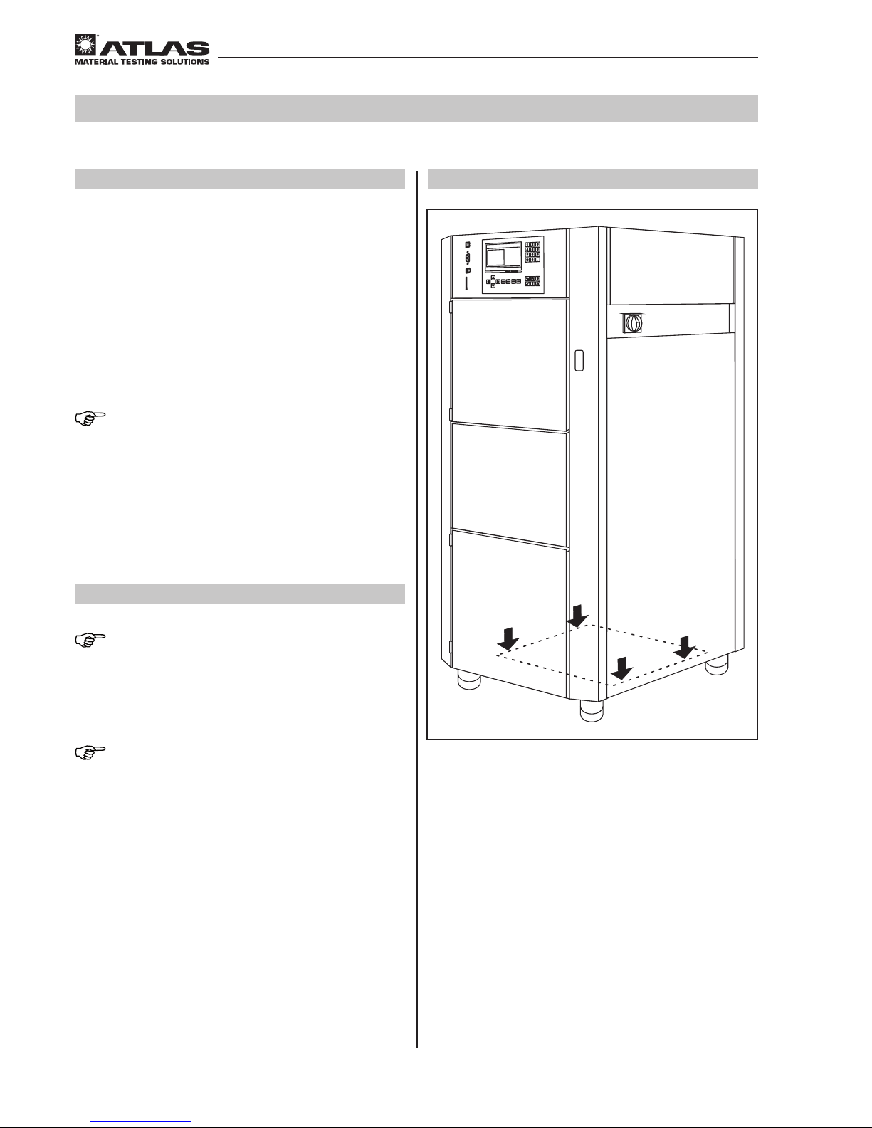
3.5 Transport
NOTE – Transport
The instrument may only be transported by experienced
service personnel using suitable equipment. The instrument may not be lifted by the front or side doors for
transport.
NOTE – lifting points (fig. 1)
The instrument may only be lifted at the lifting points
indicated in fig. 1.
Fig. 1
Page 13
- 13 -
Operating Manual Xenotest® 440
Inhalt/Content/Sommaire
3
Requirements for the installation site
3.6 Space requirements
Position the instrument on a sufficiently stable, nonflammable floor and align horizontally.
Weight of the instrument:
• Xenotest® 440 approx. 290 kg
NOTE – load at the installation site
If several instruments are to be installed in a room, ensure the static load-bearing capacity of the floor.
An access area of at least 1 m is needed around the
machine to allow for operation, maintenance and repair
work, see fig. 2 (page 14).
• Instrument dimensions:
900 mm × 780 mm × 1800 mm (W × D × H)
CAUTION – overheating of the instrument!
The air exchange of the instrument takes
place via air inlet and outlet openings on
the top of the instrument and the side air
vents. If the air exchange is blocked, tests
will be interrupted because the safety devices will shut the instrument off. Also, repeatedly turning the instrument on/off, will
shorten the life of instrument components.
Make sure that the ventilation openings are
always clear!
• The room of installation must have a minimum height
of 2.5 m
• Comply with the minimum distances at the side and
back of the instrument. The safety and maintenance
distances can be found in fig. 2 (page 14)
Page 14
- 14 -
Inhalt/Content/Sommaire
Operating Manual Xenotest® 440
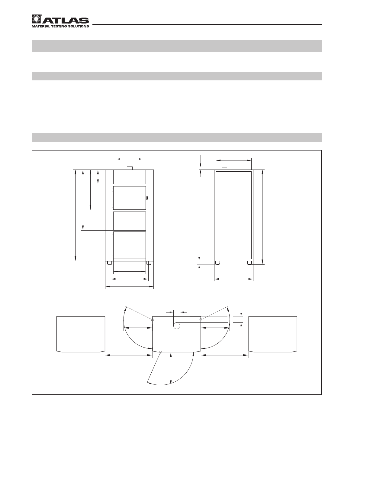
3.6 Instrument dimensions and space requirements
Fig. 2
Fig. 2:
Please see fig. 2, “Instrument dimensions” for safety and service access dimensions:
A: View from the front
B: View from the side
C: View from above
Dimensions on this drawing are in mm
3
Requirements for the installation site
A
530
1800
80
590
250
ø100
580
740
585
610
860
580
10001000
580
220
685
1110
1620
100
B
C
A
Page 15
- 15 -
Inhalt/Content/Sommaire
Operating Manual Xenotest® 440
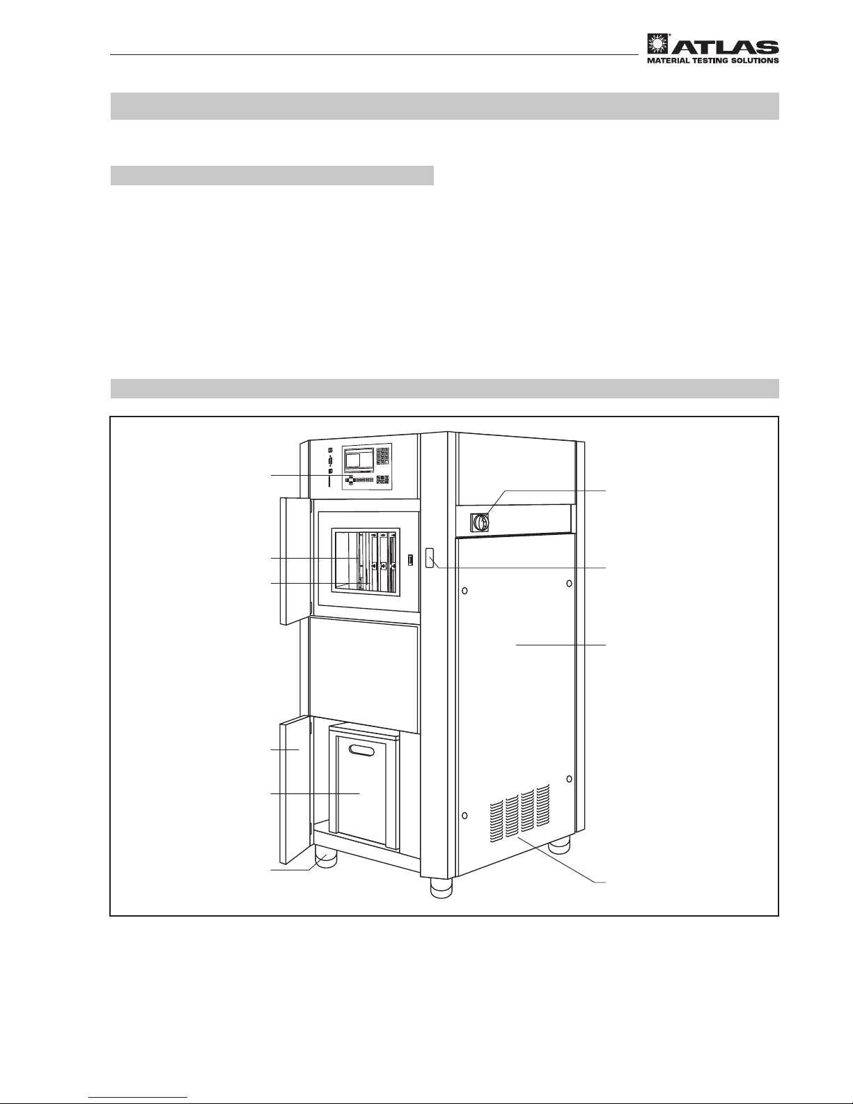
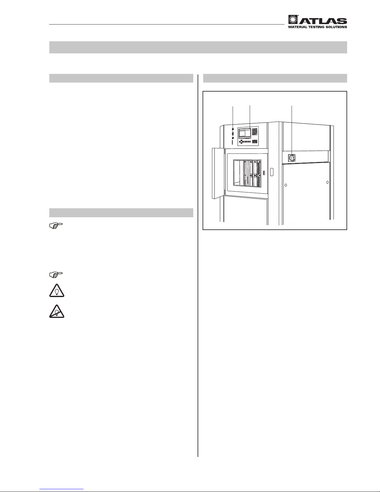
4.1 View from the front and right
Fig. 3:
View from the front:
1 Control panel with display
2 Test chamber and radiation panel
3 Sample rack with sample rack holder
4 Door to the water supply system
5 Tank for purified water
6 Height adjustable leg
4
Description of the instrument
View from the right:
7 Air inlet for the lamp cooling
8 Door to the electrical supply system
9 Door catch for the test chamber
AMain switch for turning the instrument on/off
Fig. 3
2
3
5
4
6
7
1
8
9
A
Page 16
- 16 -
Inhalt/Content/Sommaire
Operating Manual Xenotest® 440
4
Description of the instrument
4.2 View from the rear, left and above
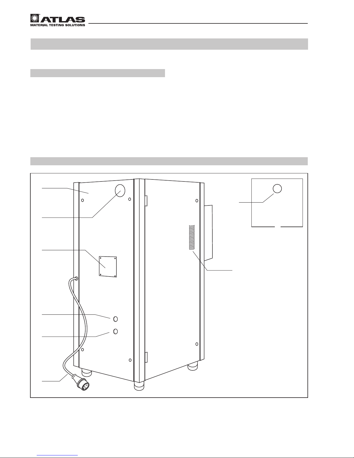
Fig. 4:
View from the rear:
1
Instrument rear panel
2
Air outlet for test chamber cooling
3
Cover panel for simple access to
the inside of the device
4
Opening for draining used water
5
Opening for supplying purified water
6
Connecting cable for supplying power to the
instrument
View from the left:
7
Air inlet for test chamber cooling
View from above:
8
Air outlet for lamp cooling
1
3
7
5
4
6
2
F
8
Fig. 4
Page 17
- 17 -
Inhalt/Content/Sommaire
Operating Manual Xenotest® 440
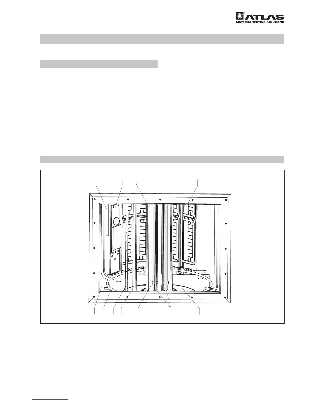
4.3 View of test chamber
Fig. 5
Fig. 5:
1
Xenon lamps for radiating material samples
2
Sample rack for holding the sample
3
Integrated sensor for measuring the test chamber temperature
and the relative humidity in the test chamber
4
Air shaft for air supply to the test chamber
5
Sample rack for revolving the samples around the xenon lamps
6
Receptacle for sample rack
7
Optical filter system for generating specific light
8
Outer cylinder
9
Exhaust air opening for discharging the heated test chamber air
A
XENOSENSIV® RC sensor for checking irradiance and
surface temperature
B
Specimen Spray System
8
5
7
9
4
3
2
1
6
A
B
4
Description of the instrument
Page 18
Operating Manual Xenotest® 440
- 18 -
Inhalt/Content/Sommaire
Fig. 6
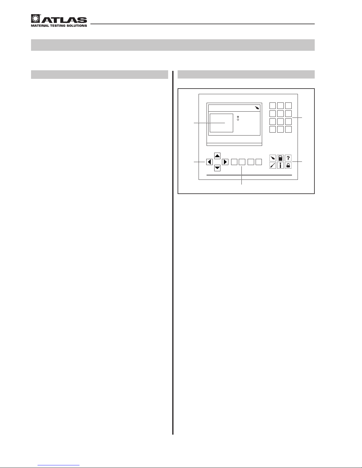
4.4 View of Xenotest® 440 control panel
Fig. 6:
1
Display that shows the menu dialogs, status displays
and program parameters
2
Arrow keys for navigation in the menus
3
Numeric keypad for entering the program parameters
and test values as well as function keys for activating
the basic functions:
• ENTER: Confirmation of the input values
• ESCAPE: Cancel the menu dialog
• START: Start a test program
• STOP: Interrupt the test
4
Menu keys
5
Numeric keypad for entering the program parameters
and test values
Start test
Test summary
-
> START
ENTER->
Test finished 10:20:15 01.08.2013
Please select test
User defined test
Standards
Test 1
Test 2
STOPSTARTESCAPE
ENTER
1
4
7
C
2
5
8
0
3
6
9
.
1
2
4
5
3
4
Description of the instrument
Page 19
- 19 -
Operating Manual Xenotest® 440
Inhalt/Content/Sommaire
5.1
Xenotest® 440 program control panel
Fig. 7:
The Xenotest 440 is turned on with the main switch 3
and then operated by the keypad on the program control
panel 2. The microprocessor-aided program control
enables both opening of already pre-programmed test
sequences and the design and initialization of userspecific tests. The parameter values required for the test
are entered with the numeric block of the keyboard and
initialized by the different function keys. The inputs and
the resulting status messages are shown in the display.
The test documentation can be output in data form via
the communication interface. Detailed specifications for
the program control and programming of test sequences
are described in the instrument’s software documentation manual.
5.2 XenoLogic™ Function
NOTE – XenoLogic function
XenoLogic is a new control technique based on two xenon lamps with which high irradiances and longer useful
lives can be achieved. The lamps are operated intelli-
gently and alternately or together as required.
NOTE – expiry of useful life
On expiry of the useful life, the lamp parame-
ters that ensure proper operation of the device
are no longer guaranteed. Especially negative
effects on the results gained with these cannot
be ruled out. Use of the lamps beyond the useful life specified by Atlas is therefore at your
own risk.
Fig. 7
1
2
3
5
Functional description
Page 20
Operating Manual Xenotest® 440
- 20 -
Inhalt/Content/Sommaire
5
Functional description
2
1
3
4
2
1
3
Fig. 8
Fig. 9
5.3 Optical filter systems
NOTE – spectral power distribution
Depending on the selected test method, the appropriate
filter system which surrounds the xenon lamps 1 in
order to create the prescribed/desired spectral energy
distribution.
5.3.1 TM16 filter system (fig. 8)
An aging-stable filter system for simulation of sunlight
behind window glass; e.g. for tests conducted in accordance with AATCC TM16. The filter system consists of:
• a filter lantern 2 with six optical filter 3
• the clamping springs for fixing the individual filter
4
5.3.2 XENOCHROME® 320 filter system/
daylight B04 filter system (fig. 9
)
Aging-stable filter systems. XENOCHROME 320 for
simulation of sunlight behind window glass; e.g. for tests
conducted in accordance with ISO 105-B02. Daylight
B04 for simulation of sunlight outdoors; e.g. for tests conducted in accordance with ISO 105-B04, -B10, 4892-2.
The filter systems consist of: a filter lantern 2 with eleven optical filter as well as an additional, uncoated compensation filter disc 3 in the XENOCHROME 320 filter
system.
Page 21

- 21 -
Inhalt/Content/Sommaire
Operating Manual Xenotest® 440
5.4 Spectral power distribution
Optical filters Outer cylinder
TM16 filter, 6 pieces Special UV glass filter
XENOCHROME
®
320, 11 pieces Special UV glass filter
Daylight B04, 11 pieces Special UV glass filter
5.4.1 Overview of optical filter systems
Table 1
5
Functional description
Page 22

- 22 -
Inhalt/Content/Sommaire
Operating Manual Xenotest® 440
5.4.2 Spectral power distribution TM16
Fig. 10: The diagram shows the spectral power distribution in the wavelength range of 300 nm – 800 nm of the
TM16 filter system in comparison with the specification of AATCC TM16.
Fig. 10
Fig. 11
5.4.3 Spectral power distribution XENOCHROME® 320 filter system
Fig. 11: The diagram shows the spectral power distribution in the wavelength range of 300 nm – 800 nm of the
XENOCHROME 320 filter system in comparison with the CIE 85 (table 4) behind 3 mm window glass.
0
0,5
1
1,5
2
2,5
3
3,5
4
4,5
5
300 350 400 450 500 550 600 650 700 750 800
Wavelength(nm)
SpectralIrradiance (W/m²/nm)
Filter System TM16
AATCC specification
0
0,5
1
1,5
2
2,5
3
3,5
4
4,5
5
300 350 400 450 500 550 600 650 700 750 800
Wavelength(nm)
SpectralIrradiance (W/m²/nm)
Filter System XENOCHROME 320
CIE85(Tab. 4) behind3mmwindow glass
5
Functional description
Page 23

- 23 -
Inhalt/Content/Sommaire
Operating Manual Xenotest® 440
5.4.4 Spectral power distribution daylight B04 filter system
Fig. 12:
The diagram represents the spectral energy distribution in the wavelength range from 300 nm to 800 nm using filter
system daylight B04 in comparison with CIE 85 (table 4).
Fig. 12
0
1
2
3
4
5
6
250 300 350 400 450 500 550 600 650 700 750 800
Spectral Irradiance (W/m²/nm)
Wavelength (nm)
Filter System XC300
CIE85, Tab. 4
5
Functional description
Page 24

- 24 -
Inhalt/Content/Sommaire
Operating Manual Xenotest® 440
5.5 Radiation System
Fig. 13:
The samples rotate on the sample rack 1 around the xenon lamps and the filter system.The irradiance is controlled
by the XENOSENSIV® RC sensor 2.
1
2
Fig. 13
5
Functional description
Page 25

- 25 -
Operating Manual Xenotest® 440
Inhalt/Content/Sommaire
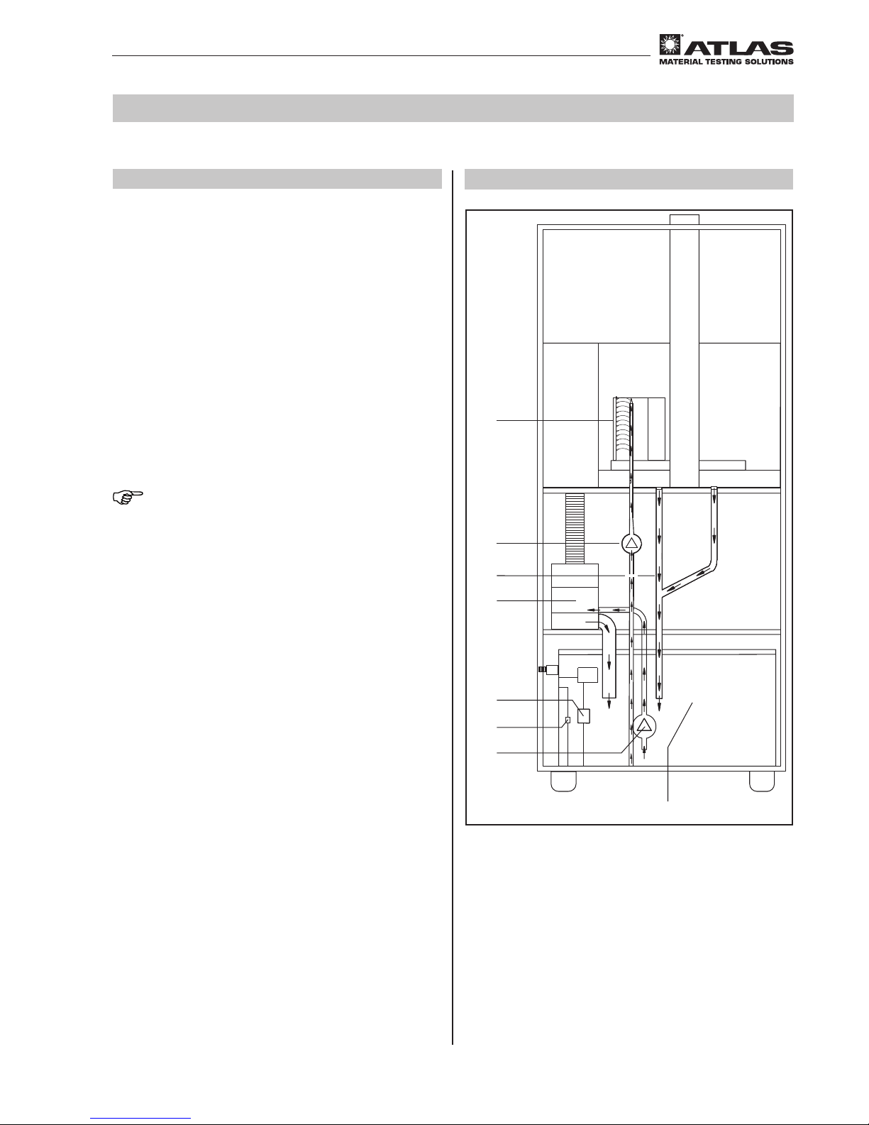
5.6 Ventilation system
The Xenotest® 440 is an air-cooled instrument. The cooling system uses two different air sources.
• Air flow system for the lamp cooling
• Air flow system for the test chamber cooling
5.6.1 Lamp cooling
Fig. 14:
The cooling air for lamp cooling is brought in by a fan
and enters through the air vents 3 on the right hand
side of the instrument. The air current flows along the
right hand module shaft and cools the electronic components first. The air is then fed through the outer cylinder 2 and cools the xenon lamps. The heated cooling
air emerges from the air vent on the top of device 1
and must be extracted by a separate exhaust system
(see 3.3).
CAUTION – overheating!
If the exhaust air current impairs the cool-
ing of the lamp, the instrument may overheat and cause damage to the samples.
The exhaust at the top of the instrument
must always be kept clear!
5.6.2 Test chamber cooling
Fig. 15:
The cooling air 1 for cooling the test chamber is brought
in by the fan 9 at the air inlet opening 7 though the
air filter 8. Depending on the temperature preset in the
test chamber, the volume of cooling air is controlled by a
motordriven vent 6. The air is fed past the heating system B where it is heated to the necessary temperature,
then mixed with humid air in the humidity system C
according to the preselected values and fed in through
the air shaft on the rear wall of the test chamber 4.
The air is distributed evenly over the sample rack 3 and
the temperature and humidity are measured continuously by the integrated sensor system 2. The used air A
is passed through the air outlet 5 in the front left section of the test chamber and, together with the heated
cooling air of the lamp cooling, is either exhausted by a
technical ventilation system or discharged directly into
the outside air.
3
2
1
B
9
8
7
A
5
6
C
1
2
34
Fig. 14
Fig. 15
5
Functional description
Page 26

Operating Manual Xenotest® 440
- 26 -
Inhalt/Content/Sommaire
5.7 Humidity function
The humidity function of the Xenotest 440 enables samples to be tested under controlled humidity conditions.
• The humidification of the test chamber is generated
by an aerosol-free ultrasonic humidifier.
Fig. 16:
The humidity system is fed from a water tank 1 inside
the instrument. The fill level of the water tank is monitored by a float valve 4. A magnetic switch 3 reports
the fill level to the program control. There is an immersion pump 2 in the water tank which supplies the humidifier 5 with water for air humidification. Water flows
back into the tank via return tubes 6.
1
2
6
5
4
3
Fig. 16
5
Functional description
Page 27
- 27 -
Operating Manual Xenotest® 440
Inhalt/Content/Sommaire
5.8 Sample spraying
The sample spraying of the Xenotest® 440 enables
spraying of the samples with the processed water during
a wet cycle.
Fig. 17:
The humidifier as well as the sample spraying are fed
from a water tank 1 inside the instrument. The filling
level of the water tank is monitored by a floating switch
4. A magnetic switch 3 reports a low water fill level to
the program control panel.
The following pumps are installed:
• The immersion pump 2 which supplies the humidi-
fier 5 with water for air humidification.
• The spray rod 7 supplies water from the water tank
into the spray lance 8 for spraying the samples.
Draining water is fed into the water tank or into a gravity
drain through the return pipe 6.
NOTE – Fresh water operation
The purity of the water is an important criterion for the
test. Therefore, it is recommended that the return line 6
is connected to the laboratory drain (gravity drain) if the
samples give off particles in the test with spraying.
The water tank inside the instrument is then constantly
supplied with fresh, processed water by a water treatment system or from an external tank.
Weathering tests of materials which release chlorine or
reactive chlorine compounds during weathering tests
or extract with spray water should only be conducted in
fresh water operation. In this case, the return pipe 6
must be connected to a laboratory drain!
1
2
6
5
4
3
7
8
Fig. 17
5
Functional description
Page 28

Operating Manual Xenotest® 440
- 28 -
Inhalt/Content/Sommaire
5.9 Measuring and control sensors
Fig. 18:
A combined temperature and humidity sensor 1 is installed in the test chamber of the Xenotest® 440.
The test chamber temperature and relative humidity are
measured and regulated with this sensor.
The functions of the sensor are:
• Display of the measured test chamber temperature
• Constant control of the test chamber temperature ac-
cording to programmed setpoint
• Display of the measured relative humidity in the test
chamber
• Constant control of the relative humidity in the test
chamber according to programmed setpoint
A XENOSENSIV® RC sensor for controlling the irradiance and surface temperature is positioned on the sample rack.
The functions of the XENOSENSIV RC sensor:
• Measurement of the surface temperature at sample
level
• Measurement of the irradiance at sample level
•
Regulation of the surface temperature (BST or BPT)
according to a programmed setpoint
• Display of the measured irradiance
• Constant control of the irradiance according to pro-
grammed setpoint
NOTE
The parameters mutually influence each other. A preliminary test should be made to establish whether the
desired values are reached (see also section 7.4 and
section 7.5).
1
Fig. 18
5
Functional description
Page 29

- 29 -
Operating Manual Xenotest® 440
Inhalt/Content/Sommaire
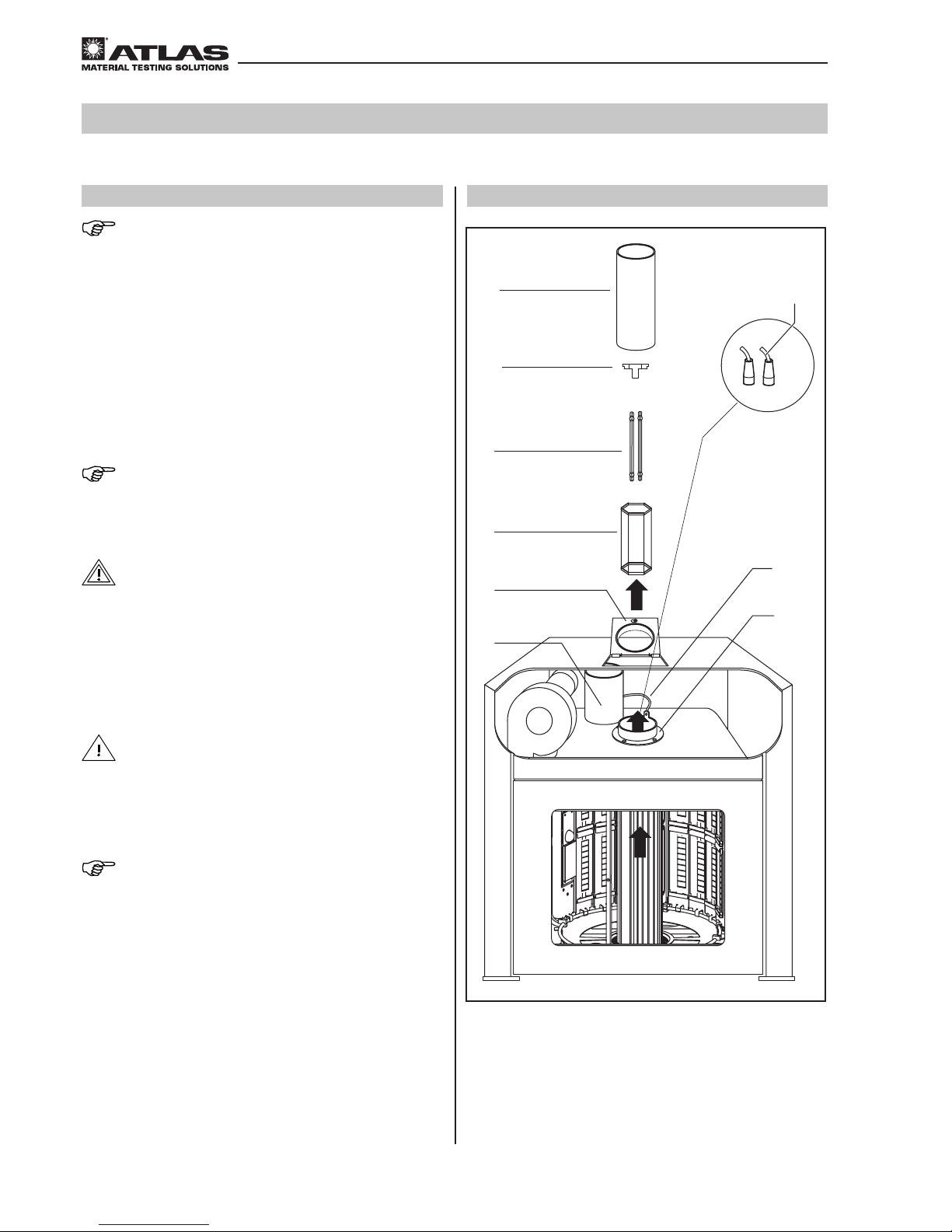
6.1 Initial start up
NOTE – first start up
The instrument may only be started for the first time by
an Atlas technical service or authorized service representative. All the functioning components of the instrument are checked during first-time start up.
6.2
Checking the instrument components
WARNING – electrical shock!
Touching live parts can lead to life threat-
ening electrical shock. Disconnect the instrument from the power supply before
checking components!
• Turn the instrument off at the ON/OFF switch
• Pull the electrical plug out of the socket and secure
against reconnecting
• Check whether the instrument is voltage free
Only instrument parts which are in optimal working condi-
tion ensure the functional reliability of the Xenotest® 440
instrument. Check the instrument components and operational functions listed below for possible damage and
operability issues before starting or before every new test
run. Do not use damaged or worn components.
Checklist:
The following functions must be checked before starting:
• Correct combination of light filters
CAUTION – overheating!
The lamp filters assist in reducing heat ra-
diation. If tests are performed without filters, the instrument can overheat and the
samples will be damaged. Only ignite the
xenon lamps when filters are properly installed.
• Number of operating hours of the xenon lamps
• Condition of the air filters for lamp cooling and test
chamber cooling
• Fit and tightness of the water hoses
• Condition of the water filter
• Fill level of the instrument’s internal water tank and
supply tank for unpurified water
• Condition of plugs and power cables
6
Start up
Page 30
Operating Manual Xenotest® 440
- 30 -
Inhalt/Content/Sommaire
6.3
Installing / removing the xenon lamps
NOTE – warranty complaint lamp set
In the event of a warranty claim, both lamps must be
sent back together with the appropriate warranty card
and the lamp file. Only then can a claim be made under
the warranty!
The lamp file of the used lamps can be saved on an SD
card under “Save settings/device/lamp age/lamp file.”
The file name corresponds to the serial number of lamp
set that is the subject of the complaint and must match
the warranty card and the lamp set. The file must be
saved before activating the new lamp set.
NOTE – XenoLogic™ function
The lamps must always be changed in pairs for the
XenoLogic function. Only then can a prolonged useful
lamp life be achieved.
WARNING – electrical shock!
Touching live parts can lead to life threat-
ening electrical shock. Disconnect the instrument from the power supply before
checking components!
• Turn the instrument off at the ON/OFF switch
• Pull the electrical plug out of the socket and secure
against reconnecting
• Check whether the instrument is voltage free
CAUTION – danger of burns!
The components of the lamp unit get very
hot and can cause burns when they come
into contact with the skin. Let the components of the lamp unit cool down sufficiently before changing the xenon lamps!
NOTE – handling the xenon lamps
Residue from finger marks can burn into the glass tubes
of the xenon lamps and cause uneven light radiation:
• Only hold the xenon lamps by the base
• Wear clean cotton gloves when handling the lamps
3
2
1
5
7
6
4
8
9
Fig. 19
6
Start up
Page 31

- 31 -
Operating Manual Xenotest® 440
Inhalt/Content/Sommaire
6.3.1 Removing the xenon lamps
Fig. 19 (page 30):
1. Remove the exhaust air channel adapter 1 or the
technical ventilation system.
2.
Lift up the exhaust air cover with connection nozzle 4.
3. Lift the intermediate tube 5 off the flange tube 7
and set aside. The intermediate tube is simply placed
on top, but is connected to the flange tube by a PE
conductor cable 6.
4. Pull the contact socket 8 off the lamp.
5. Remove the lamp covering 9.
6. Remove the filter assembly 3 up out of the exhaust
air shaft.
7. Lift the used xenon lamps 2 up and out of the lamp
socket carefully.
6.3.2 Installing the xenon lamps
Fig. 20:
1. Push the xenon lamps 1 through the flange tube,
place in the lamp socket and press in carefully.
2. Place the lamp covering 3 onto the xenon lamps.
3. Fit the contact socket 4 to the lamp.
4. Place the intermediate tube 5 onto the flange tube
2
. Make sure that the PE conductor cable is screwed
to the flange tube and the lamp plug cable is in the
recess.
5. Close and lock the exhaust air cover with the connection nozzle 6.
6. Mount the exhaust air adapter or the technical ventilation system.
CAUTION – overheating!
The lamp filters also assist with heat ab-
sorption. If tests are performed without filters, the instrument can overheat and the
samples will be damaged. Only ignite the
xenon lamps when filters are properly installed.
NOTE – lamp ignition
The radiation system is turned off by opening the exhaust air cover on the top of the instrument. The system
must be reignited to continue radiation after closing the
cover.
6
5
2
1
3
4
Fig. 20
6
Start up
Page 32

Operating Manual Xenotest® 440
- 32 -
Inhalt/Content/Sommaire
6.4 Changing optical filters
WARNING – electrical shock!
Touching live parts can lead to life threat-
ening electrical shock. The lamp ignition
of the instrument is under high voltage.
Disconnect the instrument from the main
power supply before installing/removing
the xenon lamps!
• Turn the instrument off at the ON/OFF switch
• Pull the electrical plug out of the socket and secure
against reconnecting
• Check whether the instrument is voltage free
CAUTION – danger of burns!
The components of the lamp unit get very
hot and can cause burns when they come
into contact with the skin. Let the components of the lamp unit cool down sufficiently before changing the xenon lamps!
NOTE – handling the filter
Residue from finger prints can burn into the filter and
cause uneven light radiation. Wear clean cotton gloves
when handling the filters.
Removing the filter assembly:
1. Remove the exhaust air components (see sect. 6.3)
2. Pull the contact socket off the lamps
3. Remove the lamp covering
4. Remove the lamps
5. Remove the filter assembly from the exhaust air shaft
carefully. Make sure that the xenon lamps are not
damaged
6.3.3 Setting the replacement schedule
for the lamps
The counters for the useful life of the lamps must be
reset after installing new lamps. A lamp code is enclosed
with every lamp set in which special lamp properties are
coded. By using these data, XenoLogic™ can optimize
the activation of the lamps and prolong the useful life.
The counters for the useful life of the lamps are also
reset by entering this code.
The user has the following options for entering the lamp
code:
Automatic read-in of SD card
If the lamp code is available on an SD card, it can be
read in automatically by the controller:
1. Change lamps as described in section 6.3.2.
2. Insert SD card with lamp code into the device control-
ler.
3. Read in the lamp code with “Settings / Device /
Lamp set / New lamp set.”
4. A prompt appears on the screen whether the coun-
ters for the useful life of the lamps are to be reset.
5. Confirm the prompt.
Manual input of the lamp code
1. Change lamps as described in section 6.3.2.
2. Switch on device.
3. Enter the lamp code under “Settings/Device/ Useful
life lamps/ Reset.”
4. A prompt appears on the screen whether the coun-
ters for the useful life of the lamps are to be reset.
5. Confirm prompt
NOTE – lamp code
The lamp code can only be used once to reset the useful
life of the lamps!
NOTE – expiry of useful life
On expiry of the useful life, the lamp parame-
ters that ensure proper operation of the device
are no longer guaranteed. Negative effects on
the results obtained with these expired lamps
cannot be ruled out. Therefore, use of the
lamps beyond the useful life specified by Atlas
is at your own risk.
6
Start up
Page 33

- 33 -
Operating Manual Xenotest® 440
Inhalt/Content/Sommaire
6.4 Changing optical filters
Inserting optical filters (fig. 21)
XENOCHROME
®
320 / B04:
1. Clean the filter discs with a dry, soft cloth.
2. Insert the filter discs 1 into the opening 3 of the
filter assembly 2 from above.
3. Push the filter discs into position within the holder until it stops.
The XENOCHROME 320 and B04 optical filter systems
consist of eleven filter discs. The appropriate filter as-
sembly is required to accommodate the filter discs.
TM16:
1. Clean the filter discs with a dry, soft cloth.
2. Push the filter discs 1 into the filter assembly guides
from the side.
3. Fix the filter discs with the spring at the top and bottom edges (cut-outs).
The TM16 optical filter system consists of six filter discs.
The appropriate filter assembly is required to accommo-
date the filter discs.
Installing filter lantern:
1. The filter lantern is inserted into the outer tube from
above and turned into position
2. Install the xenon lamps
3. Insert lamp alignment part
4. Fit the contact sockets to the lamps
5. Fit exhaust components
Installing/removing the outer cylinder (fig. 22)
Removal:
1. Remove the xenon lamps system (see sect. 6.3).
2. Remove the filter assembly 1 from the outer cylin-
der 6.
3. Loosen the four fastening screws 2 of the flange
tube.
4. Open the test chamber door and push up the tube
nozzle of the loosened flange tube slightly from the
inside.
5. Remove the outer cylinder 6.
Installation:
6. Insert the lower sealing ring 5 into the guide groove
and insert the outer cylinder 6 through the test
chamber door from the front.
7. Place the upper sealing ring 4 into the tube nozzle
on the outer cylinder.
8. Screw the flange tube tight and make sure the outer
cylinder is centered.
9. Place the filter assembly 1 into the outer cylinder.
10.
Install the xenon lamps system (see sect. 6.3).
1
2
3
1
6
5
4
1
2
3
Fig. 21
Fig. 22
6
Start up
Page 34

Operating Manual Xenotest® 440
- 34 -
Inhalt/Content/Sommaire
6.5 Loading the sample rack
The sample racks are an optional accessory and can be
ordered separately depending on the application.
NOTE – loading the sample rack
All sample holders must always be inserted into the
sample rack to guarantee reproducible test conditions.
Empty sample holders must be filled with blank samples.
6.5.1 Standard sample rack (fig. 23)
The sample rack 5 (ID no. 56079776) with dimensions
320 mm × 45 mm can be equipped with two samples 135
mm × 45 mm with a thickness of up to approx. 3 mm.
Cover plates (fig. 23)
Three different cover plates with different sized exposure surfaces are available for the standard sample
rack. Cover plates serve as a direct visual comparison
between the exposed and unexposed sample surfaces.
1
Cover plate 27 mm, compl. set (ID no. 56050992)
2
Cover plate 18 mm, compl. set (ID no. 56050990)
3
Cover plate 9 mm, compl. set (ID no. 56050988)
4Sample rack card (ID no. 56050993)
Equipping standard sample rack (fig. 24)
A standard sample rack can be equipped with two single
samples.
1. Push the sample 2 with the cover plates 3 of the
appropriate size into the sample rack 1.
2. Place the sample rack 1 with the holder 4 in the
lower sample rack bracket and with both holders on
the upper sample rack bracket 5.
NOTE – surface temperature
The materials used as a backing can influence the surface temperature of the samples.
5
4
3
2
1
1
2
3
4
5
Fig. 23
Fig. 24
6
Start up
Page 35

- 35 -
Operating Manual Xenotest® 440
Inhalt/Content/Sommaire
1
2
3
4
5
6
6.5.2 Special sample rack (fig. 25)
The special sample rack 2 (ID no. 56079777) with dimensions 320 mm × 48 mm can be equipped with two
samples 135 × 45 mm with a thickness of up to approx.
10 mm.
Cover plates (fig. 23)
For cover plates, see standard sample rack (sect. 6.5.1).
Equipping the special sample rack 2 (fig. 25)
1. Insert cover plates 1 into the sample rack 2.
2. Then insert the samples 3 followed by additional un-
derlay material if necessary (PET felt).
3. Push spacer sleeves 4 corresponding to the total
sample thickness onto the threaded pins.
4. Fit the retainer plate 5 and fix with quick-clamping
nuts 6.
NOTE
Wing nuts must be used for fixing total sample thicknesses greater than 10 mm.
Fig. 25
6
Start up
Page 36

Operating Manual Xenotest® 440
- 36 -
Inhalt/Content/Sommaire
5
4
3
2
1
6
7
3
6
1
2
4
5
6.5.3 Special sample rack 1B (fig. 26)
The special sample rack 1B (ID no. 56080037) with
dimensions 320 mm × 80 mm can be equipped with
samples with a thickness of up to approx. 10 mm. The
sample rack plate 4 fixes the samples.
Cover plates (fig. 26)
Three different cover plates with different sized exposure surfaces are available for the special sample rack
1B. Cover plates serve as a direct visual comparison
between exposed and unexposed sample surfaces.
1. Cover plate, 27 mm, set (ID no. 56052925)
2. Cover plate, 18 mm, set (ID no. 56052924)
3. Cover plate, 9 mm, set (ID no. 56052923)
4. Sample rack plate, set (ID no. 56052938)
Sample rack card (fig. 27):
Sample rack cards 2 with the dimensions 320 mm ×
80 mm × 0.5 mm are available as a backing material.
2
Sample rack card set of 100 pcs. (56052876)
NOTE – surface temperature
The materials used as a backing material can influence
the surface temperature of the samples
Equipping special sample rack 1B (fig. 27):
1. Place the sample or sample rack card 2 in the sam-
ple rack 5. Place material 4 underneath as a backing if necessary.
2. Place cover plate 1 on the samples and fix with the
retaining clips 6.
3. Place the sample rack 5 with holder 3 on the lower
sample rack bracket and with both holders 7 on the
upper sample rack bracket.
Fig. 26
Fig. 27
6
Start up
Page 37

- 37 -
Operating Manual Xenotest® 440
Inhalt/Content/Sommaire
6
Start up
3
5
4
2
5
6
7
2
1
1
4
2
2
2
3
4
5
6
Fig. 28
Fig. 29
6.5.4 Special sample rack 2B (fig. 28)
The special sample rack 2B is suitable for technical textiles or plastics, or other materials which are subjected
to mechanical tension tests after your light or weather
resistance tests.
Equipping special sample rack 2B (fig. 28):
1. Place the samples 2 in the two viewing windows of
the sample rack 6, place backing material 3 underneath the samples if necessary.
2. Place cover plate 1 on the samples and fix with the
retaining clips 5.
3. Place the special sample rack in the sample chamber
with the holder 4 in the lower sample rack bracket
and with the two holders 7 on the upper sample rack
bracket.
NOTE – surface temperature
The materials used as a backing can influence the surface temperature of the samples
6.5.5 Special sample rack 3B (fig. 29)
In order to further differentiate test series with the use of
larger quantities of samples, special sample racks with
subdivided viewing windows can be used which enable
3 samples to be placed in one sample rack.
Equipping special sample rack 3B (fig. 29):
1. Place the individual samples 2 in the respective
viewing windows of sample rack 5.
2. Place cover plate 1 on the samples and fix with the
retaining clips 4.
3. Place special sample rack in the sample chamber
with holder 3 in the lower sample rack bracket and
with the two holders 6 on the upper sample rack
bracket.
Page 38

Operating Manual Xenotest® 440
- 38 -
Inhalt/Content/Sommaire
Fig. 30
6.6 XENOSENSIV® RC
6.6.1 General
The XENOSENIV RC sends the measured data to the
instrument by a wireless connection. The instrument
must be equipped with an appropriate receiver.
The sensor is available in the following versions:
XENOSENSIV RC-34 BST
XENOSENSIV RC-420 BPT
6.6.2 Sensor allocation
Every XENOSENSIV RC must be allocated to an instrument. This is especially important when operating
several instruments. After the allocation, the instrument
only receives data from the sensor allocated to it. This
sensor may only be used in this instrument. The allocation remains valid until another sensor is allocated to the
instrument.
The ID and serial number of the sensor allocated to the
instrument can be requested by the instrument control
panel. If a sensor is allocated to several instruments,
only one of these instruments may be switched on otherwise transmission errors will occur.
Allocating XENOSENSIV RC to an instrument:
NOTE – sensor allocation
This process may not be performed on several instruments simultaneously.
• Open the XENOSENSIV menu in the instrument control panel (see software documentation manual) and
select the sensor function. Once this function is selected, for a period of approx. 10 seconds, the instru-
ment will be ready to receive a connection to a new
sensor.
• Hold the included magnet 1 (fig. 30) against the top
of the sensor for approx. 2 seconds. The sensor then
sends its contact data (frequency and channel number) to the instrument.
• The process can be repeated if necessary.
• After successful allocation, the ID and serial number
of the sensor allocated to the instrument is displayed
for verification.
• Any existing calibration factors which were determined for the old (previous) sensor must be deleted.
1
2
NOTE – screw
The screw 2 may not be removed.
NOTE – adhesive label
The field on the back of the sensor may not covered with
(metal) adhesive labels.
6
Start up
Page 39

- 39 -
Operating Manual Xenotest® 440
Inhalt/Content/Sommaire
6.6.3 Power supply
The XENOSENSIV® RC is battery-operated. The battery
has an average life of approx. three to six months depending on the operating hours of the test instrument.
NOTE – sleep mode
There is no need to remove the battery when the instrument is not in use. The sensor has a sleep mode. This is
activated when the instrument is switched off.
6.6.3.1 Monitoring of the battery voltage
The battery voltage is checked when starting and during
the test. If the battery voltage drops too low, the test is interrupted and an error message is displayed. The battery
must be changed to continue the test. We recommend
that you order a new spare battery immediately after
changing the battery. This helps avoid extended periods
of downtime. Original spare batteries can be ordered from
Atlas (ID No. 56055009).
Please observe the instructions for disposal of the battery.
NOTE – battery voltage
If the battery voltage is too low, the test is interrupted.
6.6.3.2 Changing the battery (Fig. 31)
WARNING – DANGER OF EXPLOSION
Only original spare batteries may be used.
If other batteries are used there is a danger
of explosion due to the high operating temperatures in the sensor!
1. Unscrew the cover 1, carefully disconnect the plug
2 and remove the battery.
WARNING – DANGER OF EXPLOSION
When changing without plastic sleeves
there is a danger of explosion due to shortcircuits! The battery must always be fitted
with plastic sleeves 3 before inserting into
the battery chamber.
2. Push two plastic sleeves 3 onto the new battery.
3. Make the connection 2.
4. Insert the battery into the sensor.
5. Check the seal 4 and screw the cover 1 back on.
A desiccant plate is inserted in the battery compartment
at the factory. This helps to prevent condensation. The
material of the plate is completely non-toxic. You can
dispose of the plate when necessary as part of your normal waste disposal.
1
2
3
4
Fig. 31
6
Start up
Page 40

Operating Manual Xenotest® 440
- 40 -
Inhalt/Content/Sommaire
6.6.3.3 Disposal of the battery
WARNING – DANGER OF FIRE:
Short-circuited batteries (plus and minus
pole connected) can heat up and ignite materials with a low flashpoint. Do not shortcircuit the batteries!
Disposal:
• Please dispose of the packaging materials according
to the appropriate disposal regulations.
• Old batteries should not be discarded in the domestic
waste. Consumers are asked to take the batteries to
a suitable collection point at a dealers or the local
authorities.
• They can also give old batteries to the Atlas service
technician who will then pass them on for proper disposal.
• Please also read the instructions on the battery and
the information on the documents accompanying delivery.
OBSERVE THE REGULATIONS FOR DIS-
POSAL!
Since March 24, 2006, the manufacturers are
asked to take batteries back in accordance
with the European directive 2002/96/EU WEEE
(Waste Electrical and Electronic Equipment)
in the respective national version.
Pb: Battery contains lead
Cd: Battery contains cadmium
Hg: Battery contains mercury
Fig. 32
4
1
2
3
3
6.6.4 Assembly
CAUTION – danger of burns!
The test chamber heats up considerably
during operation. Touching hot test chamber components can cause burns. Allow
the test chamber to cool down sufficiently
before installing or removing the sensors.
Fig. 32:
1. Mount the XENOSENSIV® RC Sensor 2 with the two
fastening screws 4 on the adapter 3 of the sensor
rack 1.
2. Insert the sensor holder (with mounted XENOSEN-
SIV RC) into the sample rack.
6
Start up
Page 41

- 41 -
Operating Manual Xenotest® 440
Inhalt/Content/Sommaire
6.7 Filling the water tank
Manual filling of the water tank
Fig. 33:
1. Pull open the bottom door 2 on the front of the in-
strument, which is held by a magnet.
2. Lift the lid 1 of the water tank 3. Fill the water tank
with approx. 40 to 60 liters of water (see specification
of the treated water sect. 3.4).
3. Close the lid of the water tank and then the instru-
ment door.
When connecting to an external water circuit:
1. Open the water supply.
2. Check the fill level in the water tank.
6.8 Connecting the exhaust air system
NOTE – exhaust air lamp cooling
It is highly recommended that the lamp cooling air be
connected to an exhaust air system. The instrument exhaust air system can overheat if the maximum length of
the exhaust air channel and the maximum permissible
number of two 90° bends is not observed. This may result in the instrument exhaust system overheating. In
turn, this will cause the instrument safety equipment to
continuously interrupt the power supply to the instru-
ment. Please observe the specifications for the instrument exhaust air system in sect. 3.3.
CAUTION – harmful UV radiation!
If the instrument is not connected to an on-
site exhaust system, hazardous levels of
UV radiation may be emitted. UV radiation
can cause irritation to the retina and skin.
Only operate the instrument with a functional exhaust air system installed.
Connecting exhaust air system Xenotest® 440
Fig. 34:
1. Place the adapter 1 of the customer’s exhaust air
system on the connection nozzle 2 on Xenotest 440.
The connection nozzle has a diameter of 100 mm.
2. Check whether the exhaust air system has an open
output outdoors or the on-site technical ventilation
system is ready for operation.
3
2
1
Fig. 33
2
1
Fig. 34
6
Start up
Page 42

Operating Manual Xenotest® 440
- 42 -
Inhalt/Content/Sommaire
6.9 Interfaces
Fig. 35:
The Xenotest® 440 instrument is equipped with four interfaces for exchanging data with external systems.
Network connection 1:
The test instrument can be integrated into a network via
the Ethernet port (see Software Documentation sect.
“Add-ons”).
Serial interface 2:
The RS232 interface enables measured data to be output during an ongoing test program on a computer.
USB interface 3:
Data interface according to the USB 2 standard. Measured data can be output to a computer via this interface
during an ongoing test program. Only available with later
versions of the software.
Slot 4 for memory card 5:
For updating installed instrument software, loading new
test programs or downloading measuring and test data.
The light emitting diode (LED) 6 illuminates when
data is transferred to the memory card.
NOTE – data loss
The memory card should not be removed from the slot
when the LED is illuminated.
1
2
3
4
6
5
Fig. 35
6
Start up
Page 43

- 43 -
Operating Manual Xenotest® 440
Inhalt/Content/Sommaire
6.10 Incoming power connection
WARNING – electrical shock!
Touching live parts can lead to life threat-
ening electrical shock. Check plugs and
power cables for damage before connecting to the incoming power. Damaged parts
should not be used for electrical connection!
The Xenotest® 440 is connected to an incoming voltage
of 230 V ± 10% (see technical data). The power supply
is made through a grounding plug (1P/N/PE), CEE (32 A,
3 pole, 6h). The electrical supply must be fused accord-
ing to regulations.
Connecting and turning on the instrument (Fig. 36)
1. Before connecting to the incoming power, check
whether the values of the power supply network in
the room of operation matches the data on the rating
plate on the back of the instrument.
2. If the data for voltage (V) and maximum current (A) do
not match, the instrument should not be connected.
3. Insert the PE plug 2 into a properly grounded and
fused socket.
4. Make sure that no stress or strain is put on the power
cables.
5. Set the main switch 1 to the “I” position.
1
2
Fig. 36
6
Start up
Page 44

Operating Manual Xenotest® 440
- 44 -
Inhalt/Content/Sommaire
7.1 Operating the keypad/touch-screen
Operation/programming of Xenotest® 440
Fig. 37:
The device controller is operated on the touch screen
either with a finger or a stylus:
2
Function keys for activating the basic functions and
arrow keys 1 for navigation in the menus
3
Menu keys for activating the corresponding menus
4
Numeric block for entering parameter values
Program modules
The instrument is controlled by six program modules
which can be accessed by the menu keys. Each program module is represented in the dialog window by an
icon C. The symbols have the following meanings:
Enter / change tests
Output data
Help
Change settings
Display data
User profiles
The menu keys can be accessed at all times. Which
menu is activated is shown in the display by the corresponding symbol C and a frame in the appropriate
symbol color.
Screen layout
The user menus are fairly self-explanatory. Each dialog
window contains notes about possible user actions or
working steps and displays information about the status
of an initiated action as well as general, primary information:
5
Request for user action
B
Note about next possible, executable working steps
6
Status bar with display:
• Text information 7: Test running / interrupted /
completed
• Progress indicator 8 (during a test run)
9
Time
A
Date
Fig. 37
Start test
Test summary
-
> START
ENTER->
Test finished 10:20:15 01.08.2013
Please select test
User defined test
Standards
Test 1
Test 2
STOPSTARTESCAPEENTER
1
4
7
C
2
5
8
0
3
6
9
.
Edit test ENTER
-
>
Test finished 10:20:15 01.08.2013
Please select test
User defined test
Standards
Test 1
Test 2
New
Copy
Delete
1
2
3
4
6
5
C
B
78 9A
7
Operation
Page 45

- 45 -
Operating Manual Xenotest® 440
Inhalt/Content/Sommaire
Fig. 38
Please enter your user name
Q
W
S
X
E
D
C
R
F
V
T
G
B
Z
H
N
U
J
M
I
K
Ö
Del
O
L
Ä
P
Ü
.:
A
Y
<
1
2
STOPSTARTESCAPEENTER
3546
7.1 Operating the keypad/touch-screen
Basic functions
Fig. 38:
Function keys 2 for controlling the basic functions:
confirm entry
cancel action or return to respective previously
selected menu
start program run
interrupt program run
The arrow keys 1 serve to mark an entry in a dropdown
menu.
Move the cursor up
Move the cursor down
Move the cursor, scroll to the left
Move the cursor, scroll to the right
Functions of the screen keyboard
3
First letter upper case, all others lower case (Abc).
Must be reactivated after setting a space.
4
All letters written in upper case (ABC).
5
Deletes all letters to the right of the cursor.
6
Deletes all letters to the left of the cursor.
The menu guide is described in the corresponding software documentation manual.
7.2
Turning on the instrument
Fig. 39:
Set the main switch to the “I” position.
The software control panel is initialized when the instrument is turned on at the main switch. The booting
process is indicated by an appropriate status message
in the four-line display. Input of the programs can then
begin.
7
Operation
Fig. 39
I
0
Edit test ENTER->
Test finished 10:20:15 01.08.2013
Please select test
User defined test
Standards
Test 1
Test 2
New
Copy
Delete
Page 46

Operating Manual Xenotest® 440
- 46 -
Inhalt/Content/Sommaire
7.3
Setting the test chamber humidity
The desired humidity in the test chamber is entered as
a parameter on the instrument control panel. The maximum humidity which can actually be achieved in the test
chamber depends on the ambient conditions. In addition, the amount of humidity which must be introduced
into the test chamber by the humidifier has an influence
on the maximum temperature which can be reached
in the test chamber. Under dry ambient conditions, the
maximum settable sample chamber temperature in the
device may not be reachable.
Fig. 40:
The diagram shows the maximum achievable sample
chamber humidity at a given sample chamber tempera-
ture under dry laboratory conditions, i.e. 20 °C and approx. 30% relative humidity, with closed air vent. With
the air vent open, the achievable humidities are lower
and highly dependent upon the ambient laboratory conditions.
7.4 Temperature fields
Fig. 41:
The diagram shows the ΔT temperature fields for
XENOCHROME® 320 and daylight B04 depending on
the irradiance. The black standard temperature (BST)
is regulated by the fan speed and dependent upon the
irradiance, test chamber temperature and the selected
filter system. The setting range for the fan speed is be-
tween 500 and 2,500 rpm. Minimum ΔT values are possible at maximum fan speed and maximum ΔT values at
minimum fan speed. Tolerances are possible within the
temperature fields shown in Fig. 41.
Fig. 40
Fig. 41
20 30 40 50 60 70
0
10
20
30
40
50
60
70
80
90
100
800 RPM
2500 RPM
flap closed
Chamber temperature CHT/°C
Rel. Humidity/ %
T= /°C
BST-PRT
20 40 60 80 100 120 140
5
10
15
20
25
30
35
40
45
50
55
60
65
500 RPM
XENOCHROME 320
2500 RPM
Daylight B04
Irradiance E
300-400
/ W/m
2
7
Operation
Page 47

- 47 -
Operating Manual Xenotest® 440
Inhalt/Content/Sommaire
7.5 Settings for test programs
The program controller of the Xenotest® 440 enables
programming of ten test programs in addition to the preprogrammed tests. The parameter input is menu guided
by the touch screen of the device controller.
NOTE – software documentation
The programming of the test programs is explained in
the separate software documentation manual.
7
Operation
Page 48

Operating Manual Xenotest® 440
- 48 -
Inhalt/Content/Sommaire
7.6 Calibration and adjustment
The Xenotest® 440 can be operated with different
XENOSENSIV® sensors.
Depending upon the XENOSENSIV sensor used, differ-
ent calibration sensors must be used for the calibration
and adjustment.
XENOSENSIV RC 34 BST
ID No.: 55008020
for calibration of irradiance in the range of 300 nm to
400 nm.
XenoCal® BB 300-400
ID No.: 55007863
for calibration of irradiance in the range of 300 nm to
400 nm.
XenoCal BST
ID No.: 55007861
for calibration of the black standard temperature.
XenoCal BB 300-400 BST
ID No.: 55007864
for calibration of irradiance in the range of 300 nm to
400 nm and the black standard temperature.
XENOSENSIV RC 420 BPT
ID No.: 55008021
for calibration of irradiance at 420 nm.
XenoCal NB 420
ID No.: 55007869
for calibration of irradiance at 420 nm.
XenoCal BPT
ID No.: 55007876
for calibration of black panel temperature.
The instructions in the XenoCal Sensor operating
manual must be observed.
7.6.1 Calibration of the XENOSENSIV RC
Sensor
The irradiance and the surface temperature can be
checked (calibrated) with a XenoCal during a running
test.
NOTE
When performing a calibration/adjustment, make sure
that the respective measuring variables of the calibra-
tion ensors corresponds to those of the XENOSENSIV.
Proceed as follows to calibrate:
1. Interrupt the test:
• Press thekey.
2. Insert the ready-to-measure XenoCal in place of a
sample rack in the sample rack holder. (See section
6.6 for XenoCal assembly).
3. Continue test (without rain or dark phase):
• Press thekey.
4. At the end of the recommended measuring time (see
XenoCal operating instructions) interrupt the test.
• Press thekey.
5. Remove the XenoCal from the test chamber and
read out the measured value.
An adjustment can then be made if necessary (see sect.
7.6.2).
7.6.2 Adjustment of the XENOSENSIV RC
Sensor
1. Open the appropriate adjustment menu on the instrument control panel after calibration (see software
documentation).
2. Enter the measured value read out from the XenoCal
on the keypad of the control panel. The old adjustment factor and the newly calculated adjustment factor are then shown on the display.
If the new factor is outside the range of 0.8 to 1.2, the
XENOSENSIV RC should be sent to Atlas for inspection.
3. Confirm and save the new adjustment factor:
• Press thekey.
The adjusted test parameters should be recalibrated
(measured value check) after adjustment (see sect.
7.6.1).
7
Operation
Page 49

- 49 -
Operating Manual Xenotest® 440
Inhalt/Content/Sommaire
7.7 Note on implementation
When working according to quality management principles, a validation of the integration (implementation) of
the test instrument into the existing processes usually
takes place first.
It is recommended to carry out a user validation process
with typical test materials for the selected test method.
Instructions for this can be found for example, in ISO
4892-1 or in ISO 105-B02.
7
Operation
Page 50

Operating Manual Xenotest® 440
- 50 -
Inhalt/Content/Sommaire
8.1 Turning off the instrument
The instrument can be turned off at the end of or interruption of a test program.
Turn off at the end of the test program:
• Set the main switch to the “0” position after the cool
down period.
Interrupt the test program, turn off the instrument:
1. Interrupt program run:
• Press the
STOP
key
2. Fig. 42:
Set the main switch to “0” after the cool down period
(approx. 5 minutes).
8.2 Turning off the instrument in an
emergency
Fig. 42:
Set the main switch to the “0” position or disconnect the
electrical plug from the electrical socket.
Fig. 42
I
0
8.4 Taking out of operation
CAUTION – danger of burns
In order to cool the hot samples and the
sample rack, the fan continues to operate
even after the instrument has switched off.
Do not open the test chamber until the fan
has switched off automatically. Wear protective gloves when changing samples.
1. After the fan switches off automatically, switch the
ON (I) / OFF (O) main switch to the “OFF (O)“ posi-
tion.
2. Put on protective gloves.
3. Open the sample chamber door by unlatching and
remove the samples from the test chamber.
4. Remove optional accessories from the test chamber
if necessary.
5. Clean the instrument according to sect. 10.4. “Clean-
ing.“
6. Disconnect the power supply plug for longer operat-
ing breaks.
8.3 Removing samples
CAUTION – danger of burns!
The samples heat up considerably during
a test program run. Touching the hot samples can cause burns. Wear gloves to remove the samples!
Remove samples:
1. Turn off the instrument.
2. Open the door of the test chamber.
3. Let the samples cool down sufficiently.
4. Remove the samples from the test chamber.
8
Shut down
Page 51

- 51 -
Operating Manual Xenotest® 440
Inhalt/Content/Sommaire
Disposal of the instrument in EU countries outside the Federal Republic of Germany:
Atlas instruments are classified according to the EU
directive 2012/19/EU of the European Parliament and
Commission on Waste Electrical and Electronic Equipment (WEEE) as „monitoring and control instruments for
exclusively commercial use“ (Category 9) and may NOT
be handed into public collection points.
The instruments carry the symbol (crossed
out trash can on wheels and bars) to identify electrical and electronic equipment
which came onto the EU market after August 13, 2005 and must be disposed of
separately in accordance with EU directive
2012/19/EU (WEEE) on waste electrical and
electronic equipment.
Notify the dealer from whom you purchased the instrument when you have finished using it so that he takes
back and disposes of it in accordance with the EU directive 2012/19/ EU on waste electrical and electronic
equipment.
Disposal of the instrument in non-EU countries:
CAUTION – environmental damage!
Observe the pertinent public disposal regu-
lations for protection of the environment
8.5 Decommissioning of instrument
Atlas instruments are classified according to the EU
directive 2012/19/EU of the European Parliament and
Commission on Waste Electrical and Electronic Equipment as “monitoring and control instruments for exclusively commercial use“ (Category 9) and may NOT be
handed into public collection points.
The instruments carry the symbol (crossed
out trash can on wheels and bars) to identify electrical and electronic equipment
which came onto the EU market after August 13, 2005 and must be disposed of
separately in accordance with EU directive
2012/19/EU (WEEE) on waste electrical and
electronic equipment.
A high percentage of the materials must be recycled for
environmental protection reasons.
Contact Atlas Technical Service to organize the acceptance and disposal in accordance with the Electrical and
Electronic Equipment Act (ElektroG) of the German Civil
Code I S. 762.
CAUTION – Violation of applicable law
Do NOT hand in Atlas instruments to public
collection points
Used Atlas instruments are dismantled and sorted into
separate materials by certified companies in accordance
with EU directive 2012/19/EU. The instruments must be
cleaned and free from test materials to rule out health
hazards for employees of the disposal companies.
NOTE
The user of the instrument is responsible for ensuring
that the instrument is free from health hazardous materials before handing it over to a disposal company.
Prior to collection, the disposal company requires a
safety declaration which can be obtained from Atlas.
WARNING
Contamination of the instrument with toxic,
infectious or radioactive material.
Danger of intoxication
Danger of infection
NEVER pass on the instrument for recycling in accordance with EU directive 2012/19/EU when it is soiled by
toxic substances or sources of infection. Dispose of in-
struments with irremovable toxic substances or sources
of infection as special waste in accordance with national
regulations.
8
Shut down
Page 52

Operating Manual Xenotest® 440
- 52 -
Inhalt/Content/Sommaire
9.1 Error messages and
troubleshooting
A list of all the error messages and the necessary troubleshooting can be found in the Xenotest® 440 software
documentation manual.
9
Troubleshooting
Page 53

- 53 -
Operating Manual Xenotest® 440
Inhalt/Content/Sommaire
10.1 Inspection
The instrument must be inspected annually. The scope
of the inspection includes:
• Checking the protective components of the instrument
• Checking the functional capability of the program
control panel
NOTE – warranty!
The manufacturer warrants the safety and operation on
the condition that:
• Inspection intervals are maintained
• Inspections are carried out by appropriately trained
and qualified personnel or by an Atlas Technical Service Representative
• Instructions in the operating manual are observed
NOTE – service package!
Atlas offers a service package especially adapted to the
instrument which includes inspection, measuring and
calibration services.
10.2 Repair
Repair work may only be carried out by appropriately
trained and qualified personnel or by an Atlas Technical
Service Representative. Only original spare parts should
be used to install or change instrument components.
Atlas will not be responsible for instrument components
or parts from third-party manufacturers.
10
Maintenance
Page 54

Operating Manual Xenotest® 440
- 54 -
Inhalt/Content/Sommaire
10.3 Maintenance
WARNING – electrical shock!
Touching live parts can lead to life threat-
ening electrical shock. Disconnect the instrument from the power supply before beginning maintenance work!
• Turn off the instrument at the main ON/OFF
switch
• Pull the electrical plug out of the socket
and secure against reconnecting
• Check whether the instrument is voltage
free
Cleaning the air filters:
The air filters for lamp cooling and test chamber cool-
ing must be cleaned every six months. Place the filter
in warm water with a mild detergent and rinse well. In
case of excessive dirt, tap the filter mat clean, vacuum
it or blow it out using soft compressed air, then clean it
in water.
Changing the air filters:
The two filters must be changed with new filters after
cleaning the existing filters twice.
Removing and installing the lamp cooling air
filter
Fig. 43:
1. Open the right hand instrument door 1.
2. Pull the filter 3 to the right out of the holder 2.
3. Push the filter into the holder.
4. Close the instrument door again.
Removing and installing the test chamber cooling air filter
Fig. 44
1. Pull the filter 1 up out of the holder 2.
2. Push the filter into the holder.
3
2
1
1
2
Fig. 43
Fig. 44
10
Maintenance
Page 55

- 55 -
Operating Manual Xenotest® 440
Inhalt/Content/Sommaire
10.3 Maintenance
Changing the xenon lamps
To maintain constant radiation, it is necessary to replace
the xenon lamps only in pairs (see sect. 5.2. and sect.
6.3). The recommended change is indicated on the pro-
gram control panel. The age of the xenon lamps can
also be reviewed during the program run (see software
documentation manual).
Cleaning the water filter:
The water pump dirt filter must be cleaned every six
months. In case of heavy debris caused by degraded
sample material during testing, the dirt filter must be replaced. The filter should be replaced with a new filter
after cleaning it twice.
Removing and installing the dirt filter
Fig. 45:
The filter 6 is part of the water pump 2. The water
pump is installed in the instrument’s water tank 1.
1. Turn off the instrument at the main power switch, pull
the electrical plug from the outlet and secure it to prevent reconnection.
2. Pull the water hose off the connection nozzle 3.
3. The water pump is affixed to the bottom of the water
tank by suction pads 5. Release the water pump
from the bottom of the tank by pulling gently.
4. The protective grille 4 is fit onto the pump housing.
Pull off the protective grille.
5. Take the filter 6 out of the protective grille 4 and
rinse well with luke warm water.
6. Reinsert the filter into the protective grille and fit the
protective grille onto the pump housing.
7. Place the water pump on the bottom of the water tank
and press gently to adhere the suction pads to the
bottom of the water tank.
Cleaning the water tank (fig. 45)
In order to prevent build up in the pipe system and the
test chamber, the water tank should be emptied and
rinsed with clean water before every new test program.
1. Open the lower instrument door.
2. Pull the water tank forward and remove the front lid.
3. Empty the water tank 1.
4. Dry with a clean cloth.
1
4
5
6
23
4
Fig. 45
10
Maintenance
Page 56

Operating Manual Xenotest® 440
- 56 -
Inhalt/Content/Sommaire
10.4 Cleaning
Cleaning the filters and outer cylinders
Cleaning step 1: with deionized water and citric acid.
Removes acid soluble residue.
Cleaning step 2: deionized water.
Removes polar residues incl. residues from step 1.
Cleaning step 3: Ethanol absolute.
Removes organic residues.
NOTE – handling the filter plates
Residue from touching with fingers can burn into the filter plates and cause uneven irradiance.
• Wear cotton gloves to clean filters and glass compo-
nents.
Cleaning the test chamber
Clean the test chamber with liquid stainless steel cleaner
without bleach. Rinse with pure water to prevent clean-
ing agent residue from contaminating the water circulation system.
Cleaning the instrument surface
CAUTION – plastic surfaces!
Parts of the instrument surface are made
of plastic. Solvents can attack plastics and
damage them. Do not clean the top of the
instrument and especially the control panel
with solvents containing hydrocarbons.
Clean the instrument surface with a solution of warm water and mild detergent, wipe the surface clean and dry
with a clean cloth.
10
Maintenance
Page 57

- 57 -
Inhalt/Content/Sommaire
Operating Manual Xenotest® 440
10.5 Consumable parts
CAUTION – approved consumable parts
The safety and reliability of the instrument is only guaranteed if the defined consumable parts listed
below are used. The use of other parts may hold hidden risks and is prohibited.
Item Designation Change to Life ID No. Section
1 Lamp
Set of xenon lamps (2 pcs.) NXE 2203 1,500 hours (each lamp) 56055329 6.3
2 Optical filter
Outer cylinder “UV special glass“ 15,000 hours 56052871 6.4
Outer cylinder seal once per year 56050886 6.4
XENOCHROME
®
320 25,000 (non-aging) 56052879 6.4
TM 16 25,000 (non-aging) 56055285 6.4
Daylight B04 25,000 (non-aging) 56079944 6.4
3 Air filter
Air filter test chamber
dependent on
ambient conditions
56055286 10.3
Air filter door
dependent on
ambient conditions
56052455 10.3
4 Water filter
Water filter
dependent on
ambient conditions
56051873 10.3
5 Battery
Battery
dependent on
ambient conditions
56055009 6.6.3
Here you can find the consumable parts recommended by Atlas which can be changed by the user.
Table 2
10
Maintenance
Page 58

Operating Manual Xenotest® 440
- 58 -
Inhalt/Content/Sommaire
11. Technical Data
Incoming power:
Incoming power connection: 3P/N/PE
CEE (32A,5-pol.,6h)
Nominal voltage: 400V ±10%
Nominal frequency: 50/60 Hz
Rated curr: max. 28 A
Nominal power: max. 8 kVA
Nominal power of xenon lamps: 2200 VA
Power of the xenon lamps: 16.5 A
Source:
Light source: 2 xenon lamps, air-cooled
Lamp life (guaranteed): 1.500 h each
Sample chamber:
Capacity: app. 2310 cm² (with XENOSENSIV)
Sample chamber temp.*: 20 °C – 65 °C
Black standard temperature*: 20 °C – 115 °C
Black panel temp.*: 20 °C – 110 °C
Relative humidity: 10% – 95%
Fan speed: 800 – 2500 rpm
Irradiance input limits:
Filter TM16 0.7 W/m² – 1.25 W/m² (420 nm)
Filter TM16 30 W/m² – 65 W/m² (300 – 400 nm)
XENOCHROME® 320
30 W/m² – 90 W/m² (300 – 400 nm)
Daylight B04 30 W/m² – 120 W/m² (300 – 400 nm)
Water capacity:
Water tank capacity: 60l
Water quality:
Conductance: <5μ S/cm
pH- value: 6 – 8
Solid content: <1ppm
Silicate content
(measured as silicon dioxide SiO2): <0.1ppm
Ultrapure water consumption:
Spraying: 0.7l/min
Humidity:
(100% activation oft the humidifier): 0.033 l/min
Connection conditions purified water:
Minimum pressure: 2 bar ±0.5 bar
Cooling air requirement:
Radiator cooling: max. 150m3/h
Sample chamber: max. 100m3/h
Interfaces:
RS232
Memory chip
Ethernet
Data recording:
RS232
Memory chip
Dimensions and weight:
Dimensions: 900 mm × 780 mm × 1800 mm
Empty weight (without operating media): app. 290kg
Noise:
Noise level: <70 db(A)
Ambient conditions:
Room temperature: max. 18 °C – 25 °C
Relative humidity: max. 50% (±10%)
Laboratory conditions:
Equipment with circulating air system
Volumetric flow of incoming air of at least 300m³/h
Air filtering with filter class EU4
dust-free
* The values depend on the lamp age, the test and
laboratory conditions.
11
Technical Data
Page 59

- 59 -
Inhalt/Content/Sommaire
Operating Manual Xenotest® 440
12. Accessories
Order no.: Designation
56079772 Application kit 105-B02 (non-aging)
Included in delivery:
* XENOCHROME
®
320 filter system (non-aging)
* Sample rack set for samples with a thickness of up to 3 mm (19 pieces)
* Set of masks 9, 18 and 27 mm aperture width (38 pieces each)
* ISO blue wool scale and ISO grey scale
* Sample rack cards (130 pieces)
56079773 Application kit TM16-2004 (non-aging)
Included in delivery:
* TM16 filter system (non-aging)
* Sample rack set for samples with a thickness of up to 3 mm (19 pieces)
* Set of masks for AATCC with a square cut-out 30 x 30 mm (38 pieces)
* AATCC blue wool scale L2, L4
* AATCC grey scale for color change
* Sample rack cards (130 pieces)
56080036 Application kit Weathering (non-aging)
Included in delivery:
* Aging-stable filter system B04 (daylight outdoors)
* Sample rack set standard for samples up to 3 mm thick (19 pieces)
* Set of cover plates 9, 18 and 27 mm aperture width (38 pieces each)
* Sample rack set Special 3B; for samples up to 10 mm thick (11 pieces)
* ISO grey scale
55015500 ISO grey scale for color change
55015502 ISO Blue Wool type 1 – 8
55015505 ISO Blue Wool type 6 (for hot lightfastness testing)
55015504 Control fabric for humidity
56078624 Specimen holder for Blue Wool scale; with glass protecting against specimen spray
56078637 XenoCal
®
adapter to fit the XenoCal sensor onto the rack
12
Accessories
Page 60

- 60 -
Inhalt/Content/Sommaire
Operating Manual Xenotest® 440
13. EC Declaration of Conformity
13
EC Declaration of Conformity
Xenotest440
EUDeclarationofConformity
The manufacturer:
AtlasMaterialTestingTechnologyGmbH
Vogelsbergstraße22
63589Linsengericht
Germany
hereby declares, that the machine designated below
Machine model: Xenotest 440
Designation: Light exposure and weathering testing equipment
Conforms with the requirements of the following regulation:
EUMachineDirective2006/42/EG
In addition, the machine conforms with the requirements of the following regulation:
EU Low Voltage Directive 2006/95/EG
EU Directive on Electromagnetic Compabiliy 2004/108/EG
Applicable,
harmonized
standards, in particular: DIN EN ISO 12100
DIN EN 60204-1
DIN EN 60950
The declaration shall loose ist validity should any changes not agreed by us be made to the machine.
Name of the authorized documentation officer: Silke Hüther
Address of the authorized documentation officer: See address of manufacturer
The original declaration is enclosed with the device or can be sent by us on request.
Page 61

- 61 -
Inhalt/Content/Sommaire
Operating Manual Xenotest® 440
14. Notes
14
Notes
Page 62

- 62 -
Inhalt/Content/Sommaire
Operating Manual Xenotest® 440
14. Notes
14
Notes
Page 63

- 63 -
Inhalt/Content/Sommaire
Operating Manual Xenotest® 440
14. Notes
14
Notes
Page 64

Inhalt/Content/Sommaire
Operating Manual Xenotest® 440
Atlas Material Testing Technology GmbH
Vogelsbergstr. 22
63589 Linsengericht / Germany
(p): + 49-6051-707-140
(f): + 49-6051-707-149
email: atlas.info@ametek.de
www.atlas-mts.com
Id.-Nr.: 56352711 01/14
 Loading...