

Page 1
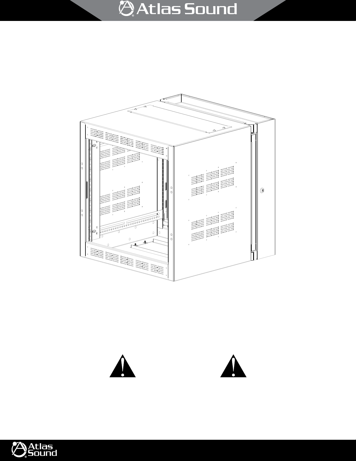
WMA Cabinets
Wall Mounted Cabinet Series
1/10
CAUTION
1. Read these instructions. Follow all instructions. Keep these instructions. Heed all warnings.
2. Use eye protection and protective gloves while unpacking the cabinet.
3. Make sure there are enough people to help safely unload and install the system. Empty rack cabinets alone may weigh up to 200 lbs. Moving rack
cabinets can present dangers to other personnel and the incorporated equipment.
©2018 Atlas Sound L.P. All rights reserved. Atlas Sound is a trademark of Atlas Sound L.P. All other trademarks are the property of their respective owners. All specs are subject to change without notice. ATS004389 P/N 490240 RevE 10/18
1601 JACK MCKAY BLVD.
ENNIS, TEXAS 75119 U.S.A.
TELEPHONE: (800) 876-3333
FAX: (800) 765-3435
AtlasSound.com
Page 2
2/10
WMA Cabinets
Wall Mounted Cabinet Series
1. Important Safety Instructions
a. These cabinet products are initially provided without installed electrical equipment and therefore are not liable for any hazards/damage
incurred by not following proper safety procedures. Installation, operation, and maintenance personnel should always follow the procedures
outlined in the National Electrical Code and any other regulations mandated by the local authorities having jurisdiction over the installation.
b. The cabinet is designed for installation and use in areas designated as "Restricted Access Location" only.
c. The installation of the cabinet is to be made by qualified service personnel in accordance with local building codes, the Installation
Instructions, and the National Electrical Code.
d. The Listing Mark on the product does not cover any of the electrical equipment, AC or DC, that may be installed in the field. The Product is
not intended to contain or house any open-frame, high-voltage electrical components like open switches, supplementary protectors, circuit
breakers, fuses, relays, etc.
e. The cabinet is intended to house audio, video, information technology, and telecommunications equipment provided with their own fire,
electrical, and mechanical enclosures.
f. Product is evaluated for use in environmentally controlled indoor areas only. The product is not to be used outdoors, in industrial or harsh
environments, or in plenum spaces.
g. The frame of the product may support a maximum load:
Model Maximum Load
WMA10-23 200 lbs
WMA12-23 200 lbs
WMA16-23 200 lbs
WMA24-23 300 lbs
WMA35-23 300 lbs
h. Use eye protection and protective gloves while unpacking and installing the cabinet.
i. Ensure adequate manpower is available to safely unload and install the product.
2. Introduction
a. This rack cabinet system is used to house rack-mounted equipment for use in audio, video, and/or data applications for network, voice,
data and video modules/devices and their associated cabling. Final equipment installer must follow individual equipment manufacturer’s
installation instructions.
b. These are wall mounted rack cabinet systems.
c. The unit’s back box is packaged separately and may be shipped to the job site where it may be installed.
d. The center section of the rack cabinet may be loaded with equipment and attached to the back box at any time. In addition, the center
section may be mounted to open in either a left or right swing-out motion.
e. The rack cabinet is provided with 1 pair of adjustable rails.
f. There is a 3RU panel in the top and bottom of the center section. These panels may be removed and replaced by other accessories such as
perforated vent panels and/or fan panels.
g. Maximum capacity of the rack cabinet is provided in the Important Safety Instructions section.
h. These cabinets all comply to U.S. and Canadian (Bi-National) Standard for Safety of Information Technology Equipment, CAN/CSA-C22.2 No.
60950-1-07, Second Edition, date March 27, 2007, UL 2416, Outline of Investigation for Audio/Video, Information and Communication
Technology Equipment Cabinet, Enclosure and Rack Systems.", Issue 2, dated 2013-07-12.
©2018 Atlas Sound L.P. All rights reserved. Atlas Sound is a trademark of Atlas Sound L.P. All other trademarks are the property of their respective owners. All specs are subject to change without notice. ATS0 04389 P/N 490240 RevE 10/18
1601 JACK MCKAY BLVD.
ENNIS, TEXAS 75119 U.S.A.
TELEPHONE: (800) 876-3333
FAX: (800) 765-3435
AtlasSound.com
Page 3
3/10
WMA Cabinets
Wall Mounted Cabinet Series
3. Required Tools
a. Razor Knife
b. Claw Hammer or Staple Remover
c. #2 Phillips Cross-Drive Screw Driver (Manual or Auto)
3
d.
e. Tape Measure (optional)
f. If installing Front Door (purchased separately) -
4. Shipping Packaging Removable
CAUTION: Ensure adequate manpower is available to help safely unload and install the system. Empty cabinets alone may weigh up to 200 lbs.
Moving rack cabinets can present dangers to both personnel and installed equipment.
CAUTION: Use eye protection and protective gloves while unpacking and installing the cabinet.
a. The cabinet will be shipped on a wood pallet. The back box and center section are in separate cartons. Select an unpacking location with
adequate surrounding space for the unloading process. In addition, plan a smooth and unobstructed route to the installation site. Low
obstructions, narrow pathways, doorsills, carpet, etc. can hinder movement. Use care when navigating obstacles. Always push from the
cabinet front or back surfaces, never pull a cabinet or push from the cabinet sides.
b. Carefully cut and remove shipping straps holding cabinet to shipping pallet.
c. Remove shrink plastic and shipping materials.
d. The back box will be found in the narrower carton. If required, this carton can be sent to a job site for mounting on a wall.
e. Use a claw hammer or staple remover to remove staples from the carton end.
f. Carefully flip carton on to the open end and pull carton off back box.
g. In most cases, the center section will be packaged in a larger carton. Use the same tools and procedure to remove the carton off the center
section.
h. Carefully cut and remove the hardware bag containing door keys, rack rail hardware, top hardware and set aside for future use.
⁄8" Hex Socket Driver
5
⁄32 L-Shaped Hex Driver Key
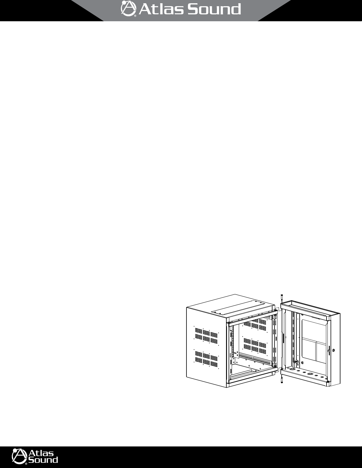
5. Cabinet Orientation
a. The back box is symmetrical. However, the knockout panel
must be mounted horizontally. In addition, the back face of this
unit is mostly solid except for the wiring access window and
wall mount holes.
b. The front of the cabinet includes the presence of ten (10)
groups of vents. In addition, there will be four (4) pairs of
threaded holes (covered with plastic plugs) to be used for
mounting accessory front doors.
c. The bottom and top of the center section has a removable 3RU
sold panel. This panel may be replaced with other accessories.
©2018 Atlas Sound L.P. All rights reserved. Atlas Sound is a trademark of Atlas Sound L.P. All other trademarks are the property of their respective owners. All specs are subject to change without notice. ATS0 04389 P/N 490240 RevE 10/18
1601 JACK MCKAY BLVD.
ENNIS, TEXAS 75119 U.S.A.
TELEPHONE: (800) 876-3333
FAX: (800) 765-3435
AtlasSound.com
Page 4

WMA Cabinets
Wall Mounted Cabinet Series
6. Initial Rail Setup
a. Adjustable rails may move forward and backward within the hat-section slot. In
addition, there is some adjustment up and down. Once rails are located as required,
use 3⁄8" hex socket driver to torque into place. Recommended torque: 82 ± 2 in-lbs.
b. Locate front rails in the front-to-back direction as required by equipment to be
installed. Once located, be sure to leave an equal gap at the top and bottom of each
rail as required.
NOTE: While front rails are typically mounted fully forward in the cabinet, this position
may not provide adequate clearance when front doors (purchased separately) are installed.
Always consider the forward space for knobs, connections, etc. as required by the installed
components.
c. If equipped with rear rack rails (presence varies with product or may be purchased
separately), use a tape measure to locate the rear rail with respect to the front rail
surface. This distance will vary with racked gear requirements. Again, be sure to
leave an equal gap at the top and bottom of each rail.
3
d. Once rails are located as required, use
⁄8" hex socket driver to torque into place. Recommended torque: 82 ± 2 in-lbs.
1
⁄4-20 Hex Bolt for
Rail Adjustment
4/10
7. Front Door Installation (purchased separately)
DID YOU KNOW? The optional front door (purchased separately) may be hung left or right- hinged as required by the final installation. The key lock
rotation may also be changed.
NOTE: Interference could exist between racked-equipment and door. See Initial Rail Setup section before proceeding.
a. Orient the door, as it will be mounted on the cabinet. The hinge side will be opposite
from the handle and lock.
b. On the hinge side, remove the 4 caps protecting the door installation points on the
cabinet. These may be discarded.
c. On the cabinet, mount the male hinge with the pins facing up. Use the two longer
10-32 x .75" cap screws found in the hardware bag to mount each male hinge.
Install using a
d. Install the two screw covers provided in the hardware bag on each male hinge.
e. Eight (8) holes are located on the hinge side of the door. There are four (4) holes
near the top and four (4) holes near the bottom. Mount the female hinge on the
door using the shorter 10-32 x .25" cap screws provided in the hardware bag. The
hinge will mount on the upper two (2) holes of the four (4) holes found near the top.
The second hinge will mount on the upper two (2) holes of the four (4) holes found
near the bottom. In each case, the female hinge will be mounted with the
hinge-hole facing down. Due to the limited space, it is best to use a L-Shaped
hex key.
f. Mount door to cabinet.
5
⁄32 hex driver key.
5
⁄32
©2018 Atlas Sound L.P. All rights reserved. Atlas Sound is a trademark of Atlas Sound L.P. All other trademarks are the property of their respective owners. All specs are subject to change without notice. ATS0 04389 P/N 490240 RevE 10/18
1601 JACK MCKAY BLVD.
ENNIS, TEXAS 75119 U.S.A.
TELEPHONE: (800) 876-3333
FAX: (800) 765-3435
AtlasSound.com
Page 5

5/10
16.00"
WMA Cabinets
Wall Mounted Cabinet Series
g. If required, the rotation and lock position may be changed to suit the user:
i. Open the door.
ii. Remove the bolt in the back of the lock.
iii. Carefully remove the lock cam and lock washer.
iv. Behind the lock cam is a special 90° washer. This washer
has a section removed and controls the lock and unlock
orientations by engaging on a protrusion on the lock body.
Carefully remove this special 90° washer.
v. Insert the key into the lock and orient to the desired locking
position.
vi. Replace the special 90° washer and then turn the key to the
unlocked position. Repeat using different orientations until the
desired locking and unlocking orientations are met. Note: The washer can be flipped if needed.
vii. Replace the lock cam, lock washer and bolt to match the desired locking and unlocking orientations.
Lock Body
90° Washer
"New" Lock Cam
Lock Washer
(May Not Be Present If Assembly
Has A Serrated Head Bolt)
Bolt
8. Wall Installation
CAUTION: Ensure adequate manpower is available to help safely install the system. Empty rack cabinets alone may weigh up to 200 lbs. Moving rack
cabinets can present dangers to both personnel and the incorporated equipment.
CAUTION: Use eye protection and protective gloves while installing the cabinet.
DID YOU KNOW? The cabinet center section may be hung left or right- hinged as required by the final installation. The key lock rotation may also be
changed. In addition, this orientation could be easily changed at any point during the cabinet’s lifetime.
a. Prepare your site for installation. A typical “2x4” stud construction was utilized during certification testing. This wall has vertical stud
centered at 16 inches. In addition, the wall was covered by
b. When installed, all back box mounting holes must be filled with a
must all be driven into the center of a vertical stud.
c. Other wall types, such as masonry, may or may not be
considered stronger. Consult site engineers/inspectors
for local code guidance.
d. Always install cabinet on a plum wall surface.
e. Layout the mounting bolt pattern on the wall. For more
detail, you may consult drawings found on
AtlasSound.com for dimensions.
f. Drill pilot holes into studs using a
g. Install back box to wall using
3
⁄16" diameter drill bit.
5
⁄16-9 x 2-½" x grade 2 lag
bolts. Use standard 5⁄16 flat washers under each lag bolt
head. All mount holes must be used.
h. If in masonry, use a rotary hammer drill with an
diameter carbide tipped hammer drill bit to provide the
hole to set a wedge anchor. Suggest using 3⁄8" ITW Red
Head “Multi-Set II” or “Trubolt” hardware.
i. Determine the hinge side of the center section.
j. Mate the cabinet center section on to the back box
and install the hinge pins completely. The ball detents
are only designed to keep the pins in place temporarily.
3
1
⁄2" thick gypsum board.
Mounting Hole Locations
⁄8"
5
⁄16-9 x 2-1⁄2" x grade 2 lag bolt and standard 5⁄16 flat washers. The lag bolts
All Heights
16.00"
All Heights
20.00" (WMA24)
30.00" (WMA35)
17.00" (WMA10)
20.00" (WMA12)
24.00" (WMA16)
20.00" (WMA24)
30.00" (WMA35)
©2018 Atlas Sound L.P. All rights reserved. Atlas Sound is a trademark of Atlas Sound L.P. All other trademarks are the property of their respective owners. All specs are subject to change without notice. ATS0 04389 P/N 490240 RevE 10/18
1601 JACK MCKAY BLVD.
ENNIS, TEXAS 75119 U.S.A.
TELEPHONE: (800) 876-3333
FAX: (800) 765-3435
AtlasSound.com
Page 6

6/10
WMA Cabinets
Wall Mounted Cabinet Series
k. Once the hinge pins are installed, the cabinet may be opened and the hairpins may be installed. The hairpins will prevent the hinge pins from
being removed.
l. The position of the lock should be on the opposite side of the hinge pins. Both the position and rotation of the lock position may be changed
to suit the user:
i. Open the cabinet.
ii. Remove the bolt in the back of the lock.
iii. Carefully remove the lock cam, lock washer and special 90° washer.
iv. If required, remove the nut holding the lock body to the back box. Now the lock body can be swapped in place of the plastic plug on the
opposite side of the cabinet. Install the nut on to the lock body.
v. Insert the key into the lock and orient to the desired locking position.
vi. Replace the special 90° washer and then turn the key to the unlocked position. Repeat using different orientations until the desired
locking and unlocking orientations are met. Note: The washer can be flipped if needed.
vii. Replace the lock cam, lock washer and bolt to match the desired locking and unlocking orientations.
Concrete Wall
Installation
Use 3/8" x 2" sleeve type
Use 3/8" x 2" sleeve type
concrete anchor bolts for
concrete anchor bolts for
concrete walls or 3/8" x 2"
concrete walls or 3/8" x 2"
toggle bolts in concrete
toggle bolts in concrete
block wall applications.
block wallapplications.
(1 bolt required per keyhole)
(1 bolt required per keyhole)
Wood Stud
Installation
Use 5/16" x 2" lag bolts and washers.
Use 5/16" x 2" lag bolts and washers.
(1 bolt required per keyhole)
(1 bolt required per keyhole)
©2018 Atlas Sound L.P. All rights reserved. Atlas Sound is a trademark of Atlas Sound L.P. All other trademarks are the property of their respective owners. All specs are subject to change without notice. ATS0 04389 P/N 490240 RevE 10/18
1601 JACK MCKAY BLVD.
ENNIS, TEXAS 75119 U.S.A.
TELEPHONE: (800) 876-3333
FAX: (800) 765-3435
AtlasSound.com
Page 7

7/10
WMA Cabinets
Wall Mounted Cabinets Series
9. Equipment Installation
CAUTION: Ensure adequate manpower is available to help safely install equipment within the rack. Despite the small size of some gear, weights can
easily reach 80 lbs. or more. Know the weight of the equipment to be installed and use the appropriate number of people or rigging equipment.
CAUTION: The center section should only be opened during installation and maintenance operations. Opening this section should not be a part of
day-to-day operations.
DID YOU KNOW? Equipment installation into the cabinet may be greatly aided by using the Atlas Sound LAR150. It provides a much-needed helping
hand during installation and also reduces manpower needed to hold the equipment in place.
DID YOU KNOW? Rail positions (rack units) are conveniently marked on all Atlas Sound cabinet rails. The 1st position will always be at the bottom of
the cabinet. The first set of three (3) mounting holes in each rail make-up this 1st rack unit position. The next set of three (3) mounting holes make-up
the 2nd rack unit position and so on.
NOTE: Interference could exist between racked-equipment, doors and floor of the cabinet. See Initial Rail Setup section before proceeding.
a. Equipment is typically mounted using 10-32 screws. Additional, matching hardware may be purchased (P/N RSCW100 or P/N RSCW500) as
required. Chrome hardware (P/N HK-40) is also available.
b. Start mounting equipment in the lower elevations of the cabinets.
c. Always mount the heaviest equipment within the lower elevations of the cabinet.
d. NOTE: If installed equipment has cooling vents on the top or bottom, do not block those vents. Leave a rack unit of space or more between
adjacent equipment. Filler panels may be used to fill these open spaces.
e. If equipment requires rear rack rails, additional rail pairs may be purchased. In general, any piece of gear heavier than 25 lbs. per rack unit
should utilize a rear rack rail. Consult chart below:
Rack Units Front Rail Max Use Front + Rear Rail Max
1 RU 25 lbs 56 lbs
2 RU 50 lbs 112 lbs
3 RU 75 lbs 168 lbs
4 RU 100 lbs 224 lbs
5 RU 125 lbs 280 lbs
f. If any type of pullout device is installed with the cabinet. Be sure cabinet center section is closed against the back box and locked before
operating pullout devise.
g. An optional fan panel may be used to help facilitate air movement within the cabinet to improve thermal cooling. Note: Fan reliability is best
when used to pull cool air. Additional reliability is gained by using an optional CFT-125 thermostat fan controller to reduce fan usage.
h. Additional air movement may be generated by installing industry-standard 119mm fans (105mm mount pattern) over the side panel perforated
vents; up to 4 fans per side.
i. Use the tie-point slots located on the rear of the main cabinet to help route and retain all electrical and AV cabling. Be sure to leave adequate
tie-points for from-wall electrical and AV service. The back box installer should leave at least a seven to eight foot service loop. This loop will
easily get to any point within the cabinet.
j. After completing the equipment installation, be sure all doors (if any) close properly.
©2018 Atlas Sound L.P. All rights reserved. Atlas Sound is a trademark of Atlas Sound L.P. All other trademarks are the property of their respective owners. All specs are subject to change without notice. ATS0 04389 P/N 490240 RevE 10/18
1601 JACK MCKAY BLVD.
ENNIS, TEXAS 75119 U.S.A.
TELEPHONE: (800) 876-3333
FAX: (800) 765-3435
AtlasSound.com
Page 8

8/10
WMA Cabinets
Wall Mounted Cabinet Series
10. Cabinet Accessories
Rear Rack Rails - A “must have” accessory for fully-supporting heavy loads within a cabinet.
WMA-RR10 RAIL PR 10RU 17IN BLK
WMA-RR12 RAIL PR 12RU 21IN BLK
WMA-RR16 RAIL PR 16RU 28IN BLK
Shelf Systems - Useful whenever equipment does not include provisions for rack-mounting. Heavier equipment may require Rear Rack Rails (listed
above) and Shelf Rear Support Brackets. Equipment may be held in place using Equipment Clamping Kit.
WMA-RR24 RAIL PR 24RU 42IN BLK
WMA-RR35 RAIL PR 35RU 61IN BLK
Shelf (10" Deep) - Cannot use Rear Support Bracket or Clamping
Kit
SH1-10 SHF VNT 1RU 10D #052
Shelf (15" Deep)
SH2-15 SHF VNT 2RU 15.5D #052
SH3-15 SHF VNT 3RU 15.5D #052
SH4-15 SHF VNT 4RU 15.5D #052
Recessed 14" Deep - Can also use Shelf Rear Support Bracket
SD2-14 STORAGE DRAWER - RECESSED 2RU W/ 14" #052
SD3-14 STORAGE DRAWER - RECESSED 3RU W/ 14" #052
SD4-14 STORAGE DRAWER - RECESSED 4RU W/ 14" #052
SD6-14 STORAGE DRAWER - RECESSED 6RU W/ 14" #052
Front & Rear Rail Sliding Shelf/Tray
VTD1-16 SLIDING SHELF/TRAY 1RU W/16"
Pull-Out Drawers - May be used to provide storage to a rack.
Shelf Rear Support Brackets
SHRSB2 SHF BRKT RR SPT 2RU SH15/SH22 #052
SHRSB3 SHF BRKT RR SPT 3RU SH15/SH22 #052
SHRSB4 SHF BRKT RR SPT 4RU SH15/SH22 #052
Equipment Clamping Kit
SHCK SHF CLP KIT SH15/SH22 SER #052
Lock Kit for Recessed 14" Deep Drawer
SD-LOCK LCK SD DRWR BLK W/B399A KEY
Rack Mount Pencil Drawer and Writing Surface
PCD3-16-052 RACK MOUNT PENCIL DRAWER
Shelf Rear Support Brackets
SHRSB2 SHF BRKT RR SPT 2RU SH15/SH22 #052
SHRSB3 SHF BRKT RR SPT 3RU SH15/SH22 #052
SHRSB4 SHF BRKT RR SPT 4RU SH15/SH22 #052
Solid Front Door
SFD10 DOR SUR 10RU 18H 20W 1D #962
SFD12 DOR SUR 12RU 21H 20W 1D #962
SFD16 DOR SUR 16RU 28H 20W 1D #962
SFD24 DOR SUR 24RU 42H 20W 1D #962
SFD35 DOR SUR 61RU 77H 20W 1D #962
3" Deep “Micro-Perf” Front Door
MPFD10-3 DOR SUR VNT 10RU 18H 20W 3D #962
MPFD12-3 DOR SUR VNT 12RU 21H 20W 3D #962
MPFD16-3 DOR SUR VNT 16RU 28H 20W 3D #962
MPFD24-3 DOR SUR VNT 24RU 42H 20W 3D #962
MPFD35-3 DOR SUR VNT 35RU 61H 20W 3D #962
Doors - Protect your equipment investments with a number of easy-to-install door options.
©2018 Atlas Sound L.P. All rights reserved. Atlas Sound is a trademark of Atlas Sound L.P. All other trademarks are the property of their respective owners. All specs are subject to change without notice. ATS0 04389 P/N 490240 RevE 10/18
1601 JACK MCKAY BLVD.
ENNIS, TEXAS 75119 U.S.A.
“Micro-Perf” Front Door
MPFD10 DOR SUR VNT 10RU 18H 20W 1D #962
MPFD12 DOR SUR VNT 12RU 21H 20W 1D #962
MPFD16 DOR SUR VNT 16RU 28H 20W 1D #962
MPFD24 DOR SUR VNT 24RU 42H 20W 1D #962
MPFD35 DOR SUR VNT 35RU 61H 20W 1D #962
Plexiglass Front Door
PFD10 DOR SUR PLX 10RU 18H 20W 1D #962
PFD12 DOR SUR PLX 12RU 21H 20W 1D #962
PFD16 DOR SUR PLX 16RU 28H 20W 1D #962
PFD24 DOR SUR PLX 24RU 42H 20W 1D #962
PFD35 DOR SUR PLX 35RU 61H 20W 1D #962
TELEPHONE: (800) 876-3333
FAX: (800) 765-3435
AtlasSound.com
Page 9

10. Cabinet Accessories
Fan Panels - Provides cooling.
9/10
WMA Cabinets
Wall Mounted Cabinet Series
Flush Fan Panels
EFT6-4 6RU FAN PANEL #962
Filler Panels - Fills in spaces left in the rail system due to wiring access, cooling, aesthetics, etc.
Economy Solid Panels
CB1 19" ECONOMY BLANK PANEL 1RU #052
CB2 19" ECONOMY BLANK PANEL 2RU #052
CB3 19" ECONOMY BLANK PANEL 3RU #052
CB4 19" ECONOMY BLANK PANEL 4RU #052
Strengthened Recessed Solid Panels
SPR1 19" BLANK 1 RU RECESSED RACK PANEL #052
SPR2 19" BLANK 2 RU RECESSED RACK PANEL #052
SPR3 19" BLANK 3 RU RECESSED RACK PANEL #052
SPR4 19" BLANK 4 RU RECESSED RACK PANEL #052
SPR5 19" BLANK 5 RU RECESSED RACK PANEL #052
SPR6 19" BLANK 6 RU RECESSED RACK PANEL #052
SPR7 19" BLANK 7 RU RECESSED RACK PANEL #052
SPR8 19" BLANK 8 RU RECESSED RACK PANEL #052
Recessed Fan Panels
EFP3-1 3RU FAN PANEL WITH 1 FAN #052
EFP3-2 3RU FAN PANEL WITH 2 FANS #052
Strengthened Flush Solid Panels
SPF2 19" BLANK 2 RU FLUSH RACK PANEL #052
Strengthened Recessed Perforated Vent Panels
PPR1 19" 1 RU RECESSED VENT RACK PANEL #052
PPR2 19" 2 RU RECESSED VENT RACK PANEL #052
PPR3 19" 3 RU RECESSED VENT RACK PANEL #052
PPR4 19" 4 RU RECESSED VENT RACK PANEL #052
PPR5 19" 5 RU RECESSED VENT RACK PANEL #052
PPR6 19" 6 RU RECESSED VENT RACK PANEL #052
PPR7 19" 7 RU RECESSED VENT RACK PANEL #052
Strengthened Flush Perforated Vent Panels
PPF2 19" BLANK 2 RU FLUSH VENT PANEL #052
Security Panels
SEC1 19" RACK MOUNT SECURITY PANEL 1RU #962
SEC2 19" RACK MOUNT SECURITY PANEL 2RU #962
SEC3 19" RACK MOUNT SECURITY PANEL 3RU #962
Hardware - Convenient packages of 10-32 rack screws with captive washers.
RSCW100 HDWR 10-32 X 3⁄4" 100/BAG PHIL SCR/CAP WSH BLK
3
RSCW500 HDWR 10-32 X
©2018 Atlas Sound L.P. All rights reserved. Atlas Sound is a trademark of Atlas Sound L.P. All other trademarks are the property of their respective owners. All specs are subject to change without notice. ATS0 04389 P/N 490240 RevE 10/18
1601 JACK MCKAY BLVD.
ENNIS, TEXAS 75119 U.S.A.
⁄4" 500/BOX PHIL SCR/CAP WSH BLK
HK-40 HDWR 10-32 X 1" 40 PHIL SCR/WSH CHR
TELEPHONE: (800) 876-3333
FAX: (800) 765-3435
AtlasSound.com
Page 10

10/10
WMA Cabinets
Wall Mounted Cabinet Series
Limited Warranty
All products manufactured by Atlas Sound are warranted to the original dealer/installer, industrial or commercial purchaser to be free from defects in
material and workmanship and to be in compliance with our published specifications, if any. This warranty shall extend from the date of purchase for
a period of three years on all Atlas Sound products, including SOUNDOLIER brand, and ATLAS SOUND brand products except as follows: one year on
electronics and control systems; one year on replacement parts; and one year on Musician Series stands and related accessories. Additionally, fuses
and lamps carry no warranty. Atlas Sound will solely at its discretion, replace at no charge or repair free of charge defective parts or products when
the product has been applied and used in accordance with our published operation and installation instructions. We will not be responsible for defects
caused by improper storage, misuse (including failure to provide reasonable and necessary maintenance), accident, abnormal atmospheres, water
immersion, lightning discharge, or malfunctions when products have been modified or operated in excess of rated power, altered, serviced or installed
in other than a workman like manner. The original sales invoice should be retained as evidence of purchase under the terms of this warranty. All
warranty returns must comply with our returns policy set forth below. When products returned to Atlas Sound do not qualify for repair or replacement
under our warranty, repairs may be performed at prevailing costs for material and labor unless there is included with the returned product(s) a written
request for an estimate of repair costs before any nonwarranty work is performed. In the event of replacement or upon completion of repairs, return
shipment will be made with the transportation charges collect.
EXCEPT TO THE EXTENT THAT APPLICABLE LAW PREVENTS THE LIMITATION OF CONSEQUENTIAL DAMAGES FOR PERSONAL INJURY, ATLAS
SOUND SHALL NOT BE LIABLE IN TORT OR CONTRACT FOR ANY DIRECT, CONSEQUENTIAL OR INCIDENTAL LOSS OR DAMAGE ARISING OUT
OF THE INSTALLATION, USE OR INABILITY TO USE THE PRODUCTS. THE ABOVE WARRANTY IS IN LIEU OF ALL OTHER WARRANTIES INCLUDING
BUT NOT LIMITED TO WARRANTIES OF MERCHANTABILITY AND FITNESS FOR A PARTICULAR PURPOSE.
Atlas Sound does not assume, or does it authorize any other person to assume or extend on its behalf, any other warranty, obligation, or liability. This
warranty gives you specific legal rights and you may have other rights which vary from state to state.
Service
Should your WMA Cabinet require service, please contact the Atlas Sound warranty department at
1-877-689-8055, ext. 277 or support.atlassound.com to obtain an RA number.
Atlas Sound Tech Support can be reached at 1-800-876-3333 or support.atlassound.com.
Visit our website at www.AtlasSound.com to see other Atlas products.
©2018 Atlas Sound L.P. All rights reserved. Atlas Sound is a trademark of Atlas Sound L.P. All other trademarks are the property of their respective owners. All specs are subject to change without notice. ATS0 04389 P/N 490240 RevE 10/18
1601 JACK MCKAY BLVD.
ENNIS, TEXAS 75119 U.S.A.
TELEPHONE: (800) 876-3333
FAX: (800) 765-3435
AtlasSound.com
 Loading...